EP0976575A1 - Classeur à anneaux - Google Patents
Classeur à anneaux Download PDFInfo
- Publication number
- EP0976575A1 EP0976575A1 EP99302055A EP99302055A EP0976575A1 EP 0976575 A1 EP0976575 A1 EP 0976575A1 EP 99302055 A EP99302055 A EP 99302055A EP 99302055 A EP99302055 A EP 99302055A EP 0976575 A1 EP0976575 A1 EP 0976575A1
- Authority
- EP
- European Patent Office
- Prior art keywords
- ring binder
- securing means
- ring
- binder mechanism
- securing
- Prior art date
- Legal status (The legal status is an assumption and is not a legal conclusion. Google has not performed a legal analysis and makes no representation as to the accuracy of the status listed.)
- Withdrawn
Links
- 239000011230 binding agent Substances 0.000 title claims abstract description 78
- 239000002184 metal Substances 0.000 description 3
- 229910000831 Steel Inorganic materials 0.000 description 1
- 230000002411 adverse Effects 0.000 description 1
- 230000004075 alteration Effects 0.000 description 1
- 238000000034 method Methods 0.000 description 1
- 238000012986 modification Methods 0.000 description 1
- 230000004048 modification Effects 0.000 description 1
- 239000010959 steel Substances 0.000 description 1
Images


Classifications
-
- B—PERFORMING OPERATIONS; TRANSPORTING
- B42—BOOKBINDING; ALBUMS; FILES; SPECIAL PRINTED MATTER
- B42F—SHEETS TEMPORARILY ATTACHED TOGETHER; FILING APPLIANCES; FILE CARDS; INDEXING
- B42F13/00—Filing appliances with means for engaging perforations or slots
- B42F13/0006—Covers for loose-leaf binders
- B42F13/0066—Covers for loose-leaf binders with means for attaching the filing appliance to the cover
- B42F13/0073—Covers for loose-leaf binders with means for attaching the filing appliance to the cover removable
Definitions
- This invention relates to a ring binder and, in particular, such a ring binder comprising a ring binder mechanism and an article, e.g. a cover, which are releasably securable to each other via securing means.
- This invention also relates to a ring binder mechanism as aforementioned.
- US Patent No. 5,286,128 issued to Gillum discloses a shield for a ring metal as having arcuate band sections at the locations of the rings and intermediate sections therebetween, the intermediate sections having a straight segmental cross section having a lower overhead clearance between the shield and the hinged leaves than the band sections.
- This document also shows a method of attaching such a ring metal to a binder cover (see e.g. col. 3, lines 35-55 and Fig. 8).
- a user may be hurt by the tabs when in use, and the overall aesthetic quality of the ring binder may also be adversely affected.
- a ring binder comprising a ring binder mechanism and a cover, wherein said cover comprises securing means via which said ring binder mechanism is releasably securable to said cover, wherein said ring binder mechanism comprises a substantially rigid upper structure supporting a pivotable lower structure to which a plurality of half-ring members are attached, wherein said lower structure is pivotably movable between a first position in which said half-ring members are closed, and a second position in which said half-ring members are open, and wherein said securing means is releasable from said lower structure only when said lower structure is in said second position.
- a ring binder mechanism releasably securable to an article via securing means
- said ring binder mechanism comprises a substantially rigid upper structure supporting a pivotable lower structure to which a plurality of half-ring members are attached, wherein said lower structure is pivotably movable between a first position in which said half-ring members are closed, and a second position in which said half-ring members are open, and wherein said lower structure is adapted to be released from said securing means only when said lower structure is in said second position.
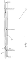
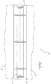
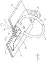
- a ring binder according to the present invention is shown in Figs. 1 to 3 generally designated as 10.
- the ring binder 10 includes a ring binder mechanism 12 and a cover 14, which are releasably secured to each other in a manner to be discussed below.
- the cover 14, which may be made of paper, cardboard or metal, includes a spine portion 16 with two adjoining flaps 18 (shown in dashed lines). For clarity purposes, the flaps 18 are not shown in other views.
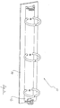
- the ring binder mechanism 12 includes a substantially rigid upper housing 20 supporting a pair of plates 22. To each of the plates 22 are fixedly attached three half-rings 24. The plates 22 we aligned with each other such that the half-rings 24 may be closed to form three rings for retaining loose-leaf paper.
- the upper housing 20 supports the plates 22, and the half-rings 24 extend through notches 26, so that the plates 22 may be pivoted relative to each other to thereby close or open the half-rings 24.
- a lever 28 which may be pivoted to act on the plates 22, and thereby to open or close the half-rings 24.
- the ring binder mechanism 12 is securable to the cover 14 via a pair of tabs 30, which are themselves fixedly secured to the cover 14 via rivets 32.
- the cover 14 includes two holes 34 for alignment with holes 36 of the tabs 30, so that the rivets 32 may be received through the holes 34 and 36, and subsequently deformed to secure the tabs 30 to the cover 14.
- each of the plates 22 includes two elongate openings 38, and the two plates 22 are positioned relative to each other such that the two pairs of elongate openings 38 are aligned to form two substantially continuous elongate apertures.
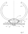
- the plates 22 may be pivoted between a position in which the upper surfaces (i.e. the surfaces facing towards the upper housing 20) of the plates 22 subtend an angle of over 180° and in which the half-rings 24 are open (as shown Figs. 6 and 7), and a position in which the upper surfaces of the plates 22 subtend an angle of less than 180° and in which the half-rings 24 are closed (as shown in Figs. 8 to 10).
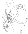
- the tab 30 includes a base 40 which abuts the cover 40, and a ledge 42 which is vertical to and at one end of the base 40, and extends towards the plates 22.
- the tab 30 also includes two wing parts 44 (see Fig. 7) extending generally upwardly and outwardly from the base 40. These wing parts 44 are received between the lower surfaces (i.e.
- Figs. 11 to 14 show various views of the tab 30. It can be seen that on each of the wing parts 44 of the tab 30 is a hole 48, which assist proper engagement of the tab 30 with the ring binder mechanism 12.
- the crimped parts 46 of the upper housing 20 includes protrusions 50 (only one is shown in the circled enlarged view of Fig. 15), each for being received within a respective hole 48 of the wing parts 44 of the tab 30.
- protrusions 50 on both lateral sides of the upper housing 20
- the engagement of the tab 30 with the ring binder mechanism 12 can be enhanced.
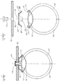
- Figs. 16A and 16B show the manner in which the ring binder mechanism 12 is engaged with, or disengaged from, the tab 30, and thus the cover 14.
- the plates 22 In order to allow the ring binder mechanism 12 and the tab 30 to be engageable with, or disengageable from, each other, the plates 22 must be in the position in which the half-rings 24 are open.
- the upper housing 20 includes two recesses 52, each for receiving a wing part 44 of the tab 30. In this position, and as shown in Fig. 16A, the tab 30 may slide relative to the ring binder mechanism 12. During the sliding movement, the wing parts 44 of the tab 30 are in contact with both the plates 22 and the crimped parts 46 of the upper housing 20.
- the tab 30 can only move until it reaches the position as shown in Fig. 16B. In this position, the protrusions 50 of the upper housing 20 are received in the respective holes 48 of the wing parts 44 of the tab 30, and the ledge 42 of the tab 30 is situated below the substantially continuous elongate aperture formed by the two elongate openings 38.
- the plates 22 may in this position be pivoted to close the half-rings 24, whereby the ledge 42 of the tab 30 extends through the substantially continuous elongate aperture formed by the two elongate openings 38, to thereby lock the ring binder mechanism 12 against any movement relative to the tab 30, and thus the cover 14, with which the tab 30 is fixedly engaged.
Landscapes
- Sheet Holders (AREA)
Applications Claiming Priority (2)
| Application Number | Priority Date | Filing Date | Title |
|---|---|---|---|
| GB9814512 | 1998-07-03 | ||
| GBGB9814512.1A GB9814512D0 (en) | 1998-07-03 | 1998-07-03 | A ring binder |
Publications (1)
| Publication Number | Publication Date |
|---|---|
| EP0976575A1 true EP0976575A1 (fr) | 2000-02-02 |
Family
ID=10834952
Family Applications (1)
| Application Number | Title | Priority Date | Filing Date |
|---|---|---|---|
| EP99302055A Withdrawn EP0976575A1 (fr) | 1998-07-03 | 1999-03-17 | Classeur à anneaux |
Country Status (2)
| Country | Link |
|---|---|
| EP (1) | EP0976575A1 (fr) |
| GB (1) | GB9814512D0 (fr) |
Citations (4)
| Publication number | Priority date | Publication date | Assignee | Title |
|---|---|---|---|---|
| EP0185634A2 (fr) * | 1984-12-18 | 1986-06-25 | Esselte Almanacksförlag Ab | Dispositif de support et de classement pour documents, feuilles de papier ou similaires |
| US5286128A (en) | 1992-09-24 | 1994-02-15 | U.S. Ring Binder | Ring binder |
| US5348412A (en) * | 1992-09-29 | 1994-09-20 | U.S. Ring Binder | Releasable attachment for a ring metal to a ring binder |
| EP0641675A2 (fr) * | 1993-09-08 | 1995-03-08 | ASOMA FASHION GmbH | Support de retenue pour classeur à feuilles volantes |
-
1998
- 1998-07-03 GB GBGB9814512.1A patent/GB9814512D0/en not_active Ceased
-
1999
- 1999-03-17 EP EP99302055A patent/EP0976575A1/fr not_active Withdrawn
Patent Citations (4)
| Publication number | Priority date | Publication date | Assignee | Title |
|---|---|---|---|---|
| EP0185634A2 (fr) * | 1984-12-18 | 1986-06-25 | Esselte Almanacksförlag Ab | Dispositif de support et de classement pour documents, feuilles de papier ou similaires |
| US5286128A (en) | 1992-09-24 | 1994-02-15 | U.S. Ring Binder | Ring binder |
| US5348412A (en) * | 1992-09-29 | 1994-09-20 | U.S. Ring Binder | Releasable attachment for a ring metal to a ring binder |
| EP0641675A2 (fr) * | 1993-09-08 | 1995-03-08 | ASOMA FASHION GmbH | Support de retenue pour classeur à feuilles volantes |
Also Published As
| Publication number | Publication date |
|---|---|
| GB9814512D0 (en) | 1998-09-02 |
Similar Documents
| Publication | Publication Date | Title |
|---|---|---|
| US5810499A (en) | Ring binder | |
| US6036394A (en) | Ring metals with linkage locking device | |
| US6276862B1 (en) | Binder mechanism | |
| US5836709A (en) | Ring binder | |
| US7950867B2 (en) | Lever for a ring binder mechanism | |
| EP0349614A4 (fr) | Mecanisme de declenchement pour classeur a anneaux. | |
| EP1568509A2 (fr) | Méchanisme de relieur à anneaux | |
| US20070283542A1 (en) | Method of Manufacturing a Ring Mechanism | |
| CA2372045A1 (fr) | Mecanisme de classeur a anneaux | |
| GB2337960A (en) | Ring binder with plurality of discrete housings for filing rings | |
| EP0976575A1 (fr) | Classeur à anneaux | |
| EP0968842A1 (fr) | Classeur à anneaux | |
| CA2179706A1 (fr) | Classeur a anneaux | |
| US5788390A (en) | Ring binder | |
| US5967690A (en) | Loose-leaf binder | |
| EP1065072A2 (fr) | Ringordnermechanismus | |
| EP2002989A1 (fr) | Mécanisme de fichier de reliure à levier | |
| EP0808725A1 (fr) | Classeur à anneaux | |
| CA2593611C (fr) | Mecanisme de reliure a fermeture souple | |
| CA2272498A1 (fr) | Logement pour mecanisme de reliure a anneaux | |
| US20070048072A1 (en) | Ring binder mechanism | |
| EP1832441B1 (fr) | Levier pour mécanisme de reliure à anneaux | |
| HK1026872A (en) | A ring binder | |
| HK1026671A (en) | A ring binder | |
| CA2315560A1 (fr) | Bati pour un mecanisme de reliure a anneaux |
Legal Events
| Date | Code | Title | Description |
|---|---|---|---|
| PUAI | Public reference made under article 153(3) epc to a published international application that has entered the european phase |
Free format text: ORIGINAL CODE: 0009012 |
|
| AK | Designated contracting states |
Kind code of ref document: A1 Designated state(s): DE ES FR GB NL |
|
| AX | Request for extension of the european patent |
Free format text: AL;LT;LV;MK;RO;SI |
|
| 17P | Request for examination filed |
Effective date: 20000228 |
|
| AKX | Designation fees paid |
Free format text: DE ES FR GB NL |
|
| STAA | Information on the status of an ep patent application or granted ep patent |
Free format text: STATUS: THE APPLICATION HAS BEEN WITHDRAWN |
|
| 18W | Application withdrawn |
Withdrawal date: 20010207 |