EP0976682A2 - Magnetisches Behandeln fluider Medien - Google Patents
Magnetisches Behandeln fluider Medien Download PDFInfo
- Publication number
- EP0976682A2 EP0976682A2 EP99305988A EP99305988A EP0976682A2 EP 0976682 A2 EP0976682 A2 EP 0976682A2 EP 99305988 A EP99305988 A EP 99305988A EP 99305988 A EP99305988 A EP 99305988A EP 0976682 A2 EP0976682 A2 EP 0976682A2
- Authority
- EP
- European Patent Office
- Prior art keywords
- fluid
- treatment device
- channels
- magnets
- fuel
- Prior art date
- Legal status (The legal status is an assumption and is not a legal conclusion. Google has not performed a legal analysis and makes no representation as to the accuracy of the status listed.)
- Withdrawn
Links
Images



Classifications
-
- C—CHEMISTRY; METALLURGY
- C02—TREATMENT OF WATER, WASTE WATER, SEWAGE, OR SLUDGE
- C02F—TREATMENT OF WATER, WASTE WATER, SEWAGE, OR SLUDGE
- C02F1/00—Treatment of water, waste water, or sewage
- C02F1/48—Treatment of water, waste water, or sewage with magnetic or electric fields
- C02F1/481—Treatment of water, waste water, or sewage with magnetic or electric fields using permanent magnets
-
- B—PERFORMING OPERATIONS; TRANSPORTING
- B01—PHYSICAL OR CHEMICAL PROCESSES OR APPARATUS IN GENERAL
- B01J—CHEMICAL OR PHYSICAL PROCESSES, e.g. CATALYSIS OR COLLOID CHEMISTRY; THEIR RELEVANT APPARATUS
- B01J19/00—Chemical, physical or physico-chemical processes in general; Their relevant apparatus
- B01J19/08—Processes employing the direct application of electric or wave energy, or particle radiation; Apparatus therefor
- B01J19/087—Processes employing the direct application of electric or wave energy, or particle radiation; Apparatus therefor employing electric or magnetic energy
-
- F—MECHANICAL ENGINEERING; LIGHTING; HEATING; WEAPONS; BLASTING
- F02—COMBUSTION ENGINES; HOT-GAS OR COMBUSTION-PRODUCT ENGINE PLANTS
- F02M—SUPPLYING COMBUSTION ENGINES IN GENERAL WITH COMBUSTIBLE MIXTURES OR CONSTITUENTS THEREOF
- F02M27/00—Apparatus for treating combustion-air, fuel, or fuel-air mixture, by catalysts, electric means, magnetism, rays, sound waves, or the like
- F02M27/04—Apparatus for treating combustion-air, fuel, or fuel-air mixture, by catalysts, electric means, magnetism, rays, sound waves, or the like by electric means, ionisation, polarisation or magnetism
- F02M27/045—Apparatus for treating combustion-air, fuel, or fuel-air mixture, by catalysts, electric means, magnetism, rays, sound waves, or the like by electric means, ionisation, polarisation or magnetism by permanent magnets
-
- B—PERFORMING OPERATIONS; TRANSPORTING
- B01—PHYSICAL OR CHEMICAL PROCESSES OR APPARATUS IN GENERAL
- B01J—CHEMICAL OR PHYSICAL PROCESSES, e.g. CATALYSIS OR COLLOID CHEMISTRY; THEIR RELEVANT APPARATUS
- B01J2219/00—Chemical, physical or physico-chemical processes in general; Their relevant apparatus
- B01J2219/08—Processes employing the direct application of electric or wave energy, or particle radiation; Apparatus therefor
- B01J2219/0803—Processes employing the direct application of electric or wave energy, or particle radiation; Apparatus therefor employing electric or magnetic energy
- B01J2219/085—Processes employing the direct application of electric or wave energy, or particle radiation; Apparatus therefor employing electric or magnetic energy creating magnetic fields
- B01J2219/0852—Processes employing the direct application of electric or wave energy, or particle radiation; Apparatus therefor employing electric or magnetic energy creating magnetic fields employing permanent magnets
-
- B—PERFORMING OPERATIONS; TRANSPORTING
- B01—PHYSICAL OR CHEMICAL PROCESSES OR APPARATUS IN GENERAL
- B01J—CHEMICAL OR PHYSICAL PROCESSES, e.g. CATALYSIS OR COLLOID CHEMISTRY; THEIR RELEVANT APPARATUS
- B01J2219/00—Chemical, physical or physico-chemical processes in general; Their relevant apparatus
- B01J2219/08—Processes employing the direct application of electric or wave energy, or particle radiation; Apparatus therefor
- B01J2219/0803—Processes employing the direct application of electric or wave energy, or particle radiation; Apparatus therefor employing electric or magnetic energy
- B01J2219/085—Processes employing the direct application of electric or wave energy, or particle radiation; Apparatus therefor employing electric or magnetic energy creating magnetic fields
- B01J2219/0862—Processes employing the direct application of electric or wave energy, or particle radiation; Apparatus therefor employing electric or magnetic energy creating magnetic fields employing multiple (electro)magnets
-
- B—PERFORMING OPERATIONS; TRANSPORTING
- B01—PHYSICAL OR CHEMICAL PROCESSES OR APPARATUS IN GENERAL
- B01J—CHEMICAL OR PHYSICAL PROCESSES, e.g. CATALYSIS OR COLLOID CHEMISTRY; THEIR RELEVANT APPARATUS
- B01J2219/00—Chemical, physical or physico-chemical processes in general; Their relevant apparatus
- B01J2219/08—Processes employing the direct application of electric or wave energy, or particle radiation; Apparatus therefor
- B01J2219/0803—Processes employing the direct application of electric or wave energy, or particle radiation; Apparatus therefor employing electric or magnetic energy
- B01J2219/085—Processes employing the direct application of electric or wave energy, or particle radiation; Apparatus therefor employing electric or magnetic energy creating magnetic fields
- B01J2219/0862—Processes employing the direct application of electric or wave energy, or particle radiation; Apparatus therefor employing electric or magnetic energy creating magnetic fields employing multiple (electro)magnets
- B01J2219/0867—Six or more (electro)magnets
-
- B—PERFORMING OPERATIONS; TRANSPORTING
- B01—PHYSICAL OR CHEMICAL PROCESSES OR APPARATUS IN GENERAL
- B01J—CHEMICAL OR PHYSICAL PROCESSES, e.g. CATALYSIS OR COLLOID CHEMISTRY; THEIR RELEVANT APPARATUS
- B01J2219/00—Chemical, physical or physico-chemical processes in general; Their relevant apparatus
- B01J2219/08—Processes employing the direct application of electric or wave energy, or particle radiation; Apparatus therefor
- B01J2219/0873—Materials to be treated
- B01J2219/0877—Liquid
Definitions
- This invention relates to apparatus for the magnetic treatment of fluids and to a method of treating fluids magnetically, particularly, but not limited to, apparatus and a method for the magnetic treatment of fuels.
- the magnetic treatment of fuels is used to increase the combustion efficiency of the fuel. Magnets are placed around a fuel pipe, thereby subjecting the fuel within the pipe to a magnetic field, and the fuel is subsequently combusted.
- the mechanism by which the combustion efficiency of the fuel is increased is not well understood, but the effect has been utilised to good effect.
- Previous apparatus for magnetising fossil fuels has involved simply securing a pair of magnets or other arrangements at an angular separation of approximately 90° on a fuel pipe. This results in the magnetic field only extending into a portion of the fuel pipe because the field does not extend across the pipe but rather through a small sector thereof. Thus, the field is not perpendicular to flow of fluid. Disadvantages arise with this type of device because the fuel passing through the fuel pipe is not all magnetised. Furthermore, placing magnets on the outside of a fuel pipe becomes very inefficient with fuel pipes having a diameter of approximately 5cms or above, since the magnetic field passes through a smaller proportion of the fuel because of attenuation of the field.
- a magnetic fluid treatment device comprises a plurality of fluid channels, each fluid channel having at least one peripherally located magnet; the device cooperating with a fluid supply conduit, so that, in use, fluid flowing through the fluid channels is subjected to a magnetic field.
- the magnet fluid treatment device may be a magnetic fuel or fossil fuel treatment device, in which case the fluid channels are fuel channels and the fluid supply conduit is a fuel supply conduit.
- the fluid channels may be water channels.
- the plurality of fluid channels may be formed by subsidiary channels of at least one major channel.
- the or each major channel may be subdivided by internal magnets located within the or each major channel.
- the internal magnets may be contained in a housing, which may, in use, prevent contact between the magnets and fluid in the channels.
- the housing may be a box section, preferably a box section of metal which contains and/or isolates magnetic fields.
- the device may include at least one flow director between adjacent subsidiary channels to improve the flow of fluid therethrough by smoothly splitting or joining the flow of fluid.
- the or each flow director may have a tapered cross-section.
- flow directors are included at leading and trailing ends of the subsidiary channels.
- the or each peripherally located magnet may be held in position by retaining means.
- the fluid channels may be located within an external housing.
- the external housing may comprise a plurality of sections which are arranged to be secured together to enclose the fluid channels.
- the external housing comprises first and second sections.
- the first and second sections may be arranged to have a central section secured therebetween.
- the central section comprises the fluid channels and a plurality of internal magnets.
- the or each peripherally located magnet may be held in position by retaining means of the external housing.
- the retaining means may be at least one flange which forms a slot with a wall, preferably an interior wall, of the external housing, into which slot the peripherally located magnet may be inserted.
- the external housing may be made of metal that will isolate and/or contain magnetic fields, such as ferritic steel or electric steel.
- the device may comprise attachment means at each end, which may be externally threaded or flanged portions, or similar attachment means to facilitate connection of the device to the fluid supply conduit.
- the device may include at least one pressure sensing means which may be located at an end of the device.
- the device includes pressure sensing means at both ends of the device.
- the magnetic field is applied substantially at right angles to the flow of fluid.
- the magnets may be arranged to have first, like poles facing inwardly towards the central axis of the channels at a first, leading end of the device. Preferably the magnets are arranged at either side of the channels.
- the magnets may be arranged to have second, like poles facing inwardly towards the central axis of the channels at a second, trailing end of the device.
- the magnets may be arranged to have opposite poles facing inwardly towards the central axis of the channels in a central section of the device.
- the sense of the first like poles may be chosen depending on the fluid to be used.
- the magnets may be arranged to have opposite poles facing inwardly towards the central axis of the channels along the length of the device.
- At least one of said fluid channels may contain a catalyst, preferably a tin alloy catalyst, to improve the combustion efficiency of fuel flowing therethrough.
- the catalyst may be held in position in a mesh bag.
- the catalyst may be held in position in the fluid channel(s) by retaining members extending across the channels, which retaining members may have a plurality of openings therein, to assist the passage of fuel therethrough.
- the retaining members may be mesh. One retaining mesh may be located upstream and one retaining mesh may be located downstream of the catalyst.
- a method for magnetically treating fluid comprises passing the fluid through a plurality of fluid channels of a fluid treatment device, each fluid channel having at least one peripherally located magnet, the fluid thereby being subjected to a magnetic field.
- the fluid may be fuel, preferably fossil fuel, in which case the fluid channels are fuel channels and the fluid treatment device is a fuel treatment device.
- the method may include subdiving the flow of fluid by means of magnets located within a major channel of the device, which magnets may thereby create subsidiary channels.
- a magnetic fluid treatment device comprises at least one fluid conduit around which are arranged a plurality of magnets, wherein the magnets are arranged to have first, like poles facing inwardly towards a central axis of the or each channel at a first region of the device, second, like poles facing inwardly towards the central axis of the or each channel at a second region thereof, and opposite poles facing inwardly towards the central axis of the channels in a third region located between the first and second regions.
- a magnetic fluid treatment device comprises at least one fluid conduit around which are arranged a plurality of magnets, wherein the magnets are arranged to have opposite poles facing inwardly towards a central axis of the or each channel.
- a magnetic fuel treatment device 10 is arranged to be fitted in line with a fuel supply pipe 12 and comprises upper and lower peripheral box sections 14 and 16 respectively into which a plurality of magnets 18 are inserted.
- the fuel treatment device 10 also comprises upper and lower central box sections 20 and 22, into which further magnets 24 are inserted. Fuel flowing through the magnetic fuel treatment device 10 on its way to a fuel combustion point or the like (not shown) is affected by the magnetic fields of the magnets 18 and 24, which results in a more efficient burning process.
- the fuel treated can be fossil fuel, such as oil and gas or equivalent fuel types.
- the magnetic fuel treatment device 10 comprises upper and lower portions 26 and 28 (see figure 2) which include the upper and lower peripheral box sections 14 and 16 respectively.
- a central portion 30 is secured between the upper and lower portions 26 and 28.
- the central portion 30 comprises a section of pipe 32 having a circular cross section and the upper and lower central box sections 20 and 22.
- the upper and lower portions 26 and 28 and the central portion 30 are secured together by means of bolts 34.
- the magnetic fuel treatment device 10 may be made of ferritic steel or electric steel generally termed magnetic containment steel, which is chosen because it does not become magnetised over time. Metals having similar properties could also be used.
- the upper and lower central box sections have a leading flow director 34, which serves to channel fuel flowing through the magnetic fuel treatment device 10 into upper and lower channels 36 and 38 and to ensure a smooth flow of the fuel.
- a corresponding trailing flow director 40 is included at the opposite end of the upper and lower central box sections 20 and 22.
- the upper and lower channels 36 and 38 preferably have a maximum width which is less than 5cms. Consequently, the fuel in a fuel pipe having a bore of between 7.5 and 10cms, for instance, can be treated efficiently with the magnetic fuel treatment device 10 disclosed herein, without any disadvantageous effects of the fuel not being treated because of a lack of magnetic field affecting the fuel.
- the upper and lower central box sections 20 and 22 which contain the magnets have a further beneficial effect over simply placing the magnets within the fuel pipe itself, which is that flakes of the magnet will not be released into the fuel which would be the case if the magnets were not enclosed. Consequently, clogging of the fuel burner due to flakes of magnet in the fuel is avoided.
- the magnets used may include the following types: ceramic grades 1, 2 and 3; anisotropic ferite; samarium cobolt 1:5-2:17; neodymium N27-N50.
- the magnets may have Gauss values in the range 200-13,000.
- a second embodiment of magnetic fuel treatment device 50 is shown in figures 3 to 5.
- the fuel treatment device 50 is arranged and constructed in a very similar way to the fuel treatment device 10, except that this fuel treatment device 50 has twin pipe sections 32 each having their own upper and lower peripheral box sections 14 and 16, and upper and lower central box sections 20 and 22.
- the second embodiment of fuel treatment device 50 has all of the features of the first embodiment, with the addition of forward and rear flow directors 52 and 54 respectively, which serve to direct the flow between the two adjacent pipe sections 32.
- the second embodiment has the additional advantage of allowing still smaller widths of channel 36 and 38, giving the required magnetic effect for treating fuel.
- larger bore fuel pipes can have the fuel efficiently treated by the magnets 18 and 24, because there are twice as many magnets 18 and 24 compared to the first embodiment - thus extending the treatment time of the fluid,
- a third embodiment of magnetic fuel treatment device 60 is shown in figures 6 and 7.
- the structure of the device is similar to the second embodiment of fuel treatment device 50 except that the upper and lower central box sections 20 and 22 are not present, resulting in the two pipe sections 32 forming open channels 62, through which fuel may pass.
- the third embodiment has the forward and rear flow directors 52 and 54 present in the second embodiment.
- the third embodiment of fuel treatment device 60 is easier and cheaper to manufacture than the first two embodiments.
- the magnetic field is preferably applied to the fuel at about 90° to the direction of flow.
- the arrangement of the magnets 18 and 24 within the box sections 14, 16, 20 and 22 can be chosen to further increase the efficiency of burn of the fuel in the fuel pipe, depending on the type of fuel used.
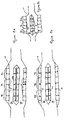
- Figures 8a and 8b show possible arrangements which have been found to be beneficial for gas and oil respectively.
- Figure 8c shows a further configuration.
- the magnets are arranged so that the gas entering the fuel treatment device 10 first encounters a first set of magnets 70 which have their north poles facing in towards the channels 36 and 38.
- a second set of magnets 71 have one north pole and one south pole facing into each of the channels 36 and 38.
- a third set of magnets 72 have their south poles facing in towards the channels 36 and 38.
- FIG 8b the order of the magnets is reversed from that shown in figure 8a.
- the first set of magnets 70 has south poles facing in towards the channels 36 and 38
- the second set 71 is the same as figure 8a, but the third set 72 has north poles facing in towards the channels 36 and 38.
- first, second and third sets of magnets 70, 71 and 72 may comprise adjacent magnets 18 and 24 having the same alignment of poles ie. two magnets 18 together having their north poles facing inwards for the first set of magnets 70, followed by a pair of adjacent magnets having the same orientation for the second set 71 and the third set 72 having adjacent magnets having the south poles facing inwards towards the channels 36 and 38. Further combinations of the alignment of the poles and the magnets can also be envisaged within the scope of the invention.
- a further embodiment of fuel treatment device is shown in figures 9a and 9b.
- This embodiment includes a catalyst 39 which can be a tin alloy catalyst containing tin, antimony, lead and mercury for improving fuel combustion efficiency.
- the catalyst is held in the fuel channels 36 and 38, either in a mesh bag (not shown) or between mesh retaining members 37. Catalysts are known to improve fuel combustion efficiency. The provision of a catalyst within the fuel channels does not significantly affect throughflow whilst providing a very compact fuel treatment device.
- the above embodiments have referred to the use of fuel in the fuel treatment device 10. If water, or other fluids, are fed through the device, it is also known that beneficial yields of plants and crops etc are achieved. Consequently, without departing from the scope of the invention the fuel treatment devices may be fluid treatment devices.
Landscapes
- Chemical & Material Sciences (AREA)
- Engineering & Computer Science (AREA)
- Chemical Kinetics & Catalysis (AREA)
- Organic Chemistry (AREA)
- Combustion & Propulsion (AREA)
- Water Supply & Treatment (AREA)
- Environmental & Geological Engineering (AREA)
- Hydrology & Water Resources (AREA)
- Life Sciences & Earth Sciences (AREA)
- Mechanical Engineering (AREA)
- General Engineering & Computer Science (AREA)
- Health & Medical Sciences (AREA)
- General Health & Medical Sciences (AREA)
- Toxicology (AREA)
- Feeding And Controlling Fuel (AREA)
- Production Of Liquid Hydrocarbon Mixture For Refining Petroleum (AREA)
- Water Treatment By Electricity Or Magnetism (AREA)
Applications Claiming Priority (2)
| Application Number | Priority Date | Filing Date | Title |
|---|---|---|---|
| GB9816332 | 1998-07-28 | ||
| GBGB9816332.2A GB9816332D0 (en) | 1998-07-28 | 1998-07-28 | Magnetic treatment of fluids |
Publications (2)
| Publication Number | Publication Date |
|---|---|
| EP0976682A2 true EP0976682A2 (de) | 2000-02-02 |
| EP0976682A3 EP0976682A3 (de) | 2000-07-05 |
Family
ID=10836243
Family Applications (1)
| Application Number | Title | Priority Date | Filing Date |
|---|---|---|---|
| EP99305988A Withdrawn EP0976682A3 (de) | 1998-07-28 | 1999-07-28 | Magnetisches Behandeln fluider Medien |
Country Status (2)
| Country | Link |
|---|---|
| EP (1) | EP0976682A3 (de) |
| GB (1) | GB9816332D0 (de) |
Cited By (7)
| Publication number | Priority date | Publication date | Assignee | Title |
|---|---|---|---|---|
| WO2001012313A1 (de) * | 1999-08-18 | 2001-02-22 | Erhard Gleich | Vorrichtung zur verbesserung des brennwerts flüssiger kraftstoffe und zur reduzierung des abgases |
| WO2005054658A1 (en) | 2003-11-28 | 2005-06-16 | Maxsys Limited | Improvements for fuel combustion |
| CN101759255B (zh) * | 2009-09-22 | 2011-11-02 | 淄博兰雁集团有限责任公司 | 节能型磁流体自动化污水净化设备及工艺 |
| FR2971952A1 (fr) * | 2011-02-28 | 2012-08-31 | Hypnow | Dispositif de traitement magnetique de fluides |
| WO2014076215A1 (en) * | 2012-11-15 | 2014-05-22 | Robert Spencer | Magnetic treatment of fluids |
| FR2998487A1 (fr) * | 2012-11-28 | 2014-05-30 | Hypnow | Dispositif compact de traitement magnetique de fluides |
| RU2708568C1 (ru) * | 2019-02-18 | 2019-12-09 | Станислав Васильевич Михайлин | Разрядник для обработки жидкостей и газов |
Family Cites Families (11)
| Publication number | Priority date | Publication date | Assignee | Title |
|---|---|---|---|---|
| BE670809A (de) * | 1965-10-12 | 1966-01-31 | ||
| JPS5825561A (ja) * | 1982-04-13 | 1983-02-15 | Katsuro Yoshimura | 配管内流体の磁場を与えるための軽量磁界処理装置 |
| GB2174146B (en) * | 1985-04-25 | 1988-11-09 | Johoku Kigyo Kabushiki Kaisha | Device for improving combustion in jet engines |
| LU87289A1 (fr) * | 1988-07-22 | 1989-02-02 | Liquitech Holding Sa | Element conditionneur de liquide |
| GB8817899D0 (en) * | 1988-07-27 | 1988-09-01 | Liff Ind Ltd | Water conditioning device |
| DE4107512A1 (de) * | 1991-03-08 | 1992-09-10 | Os Bad Rozwojowy Gospodarki En | Verfahren zur magnetischen aufbereitung von fluessigkeiten und vorrichtung zur durchfuehrung des verfahrens |
| FR2706949A1 (en) * | 1993-06-23 | 1994-12-30 | Bruot Jacques | Device intended to generate residual magnetism in a hydrocarbons (fuel) circuit, from a source |
| CN1087812C (zh) * | 1994-10-25 | 2002-07-17 | 王文浩 | 高效环保节油器 |
| US5716520A (en) * | 1995-08-30 | 1998-02-10 | Mason; Elmer B. | Magnetic fluid conditioner |
| GB9614705D0 (en) * | 1996-07-12 | 1996-09-04 | Tri Technica Limited | Fuel treatment device |
| IT1298673B1 (it) * | 1997-04-28 | 2000-01-12 | Gianni Zangrando | Dispositivo per l'eliminazione di incrostazioni e depositi calcarei in tubazioni,impianti idrici ed apparecchiature collegate agli stessi |
-
1998
- 1998-07-28 GB GBGB9816332.2A patent/GB9816332D0/en not_active Ceased
-
1999
- 1999-07-28 EP EP99305988A patent/EP0976682A3/de not_active Withdrawn
Cited By (11)
| Publication number | Priority date | Publication date | Assignee | Title |
|---|---|---|---|---|
| WO2001012313A1 (de) * | 1999-08-18 | 2001-02-22 | Erhard Gleich | Vorrichtung zur verbesserung des brennwerts flüssiger kraftstoffe und zur reduzierung des abgases |
| WO2005054658A1 (en) | 2003-11-28 | 2005-06-16 | Maxsys Limited | Improvements for fuel combustion |
| EP1803923A3 (de) * | 2003-11-28 | 2007-11-07 | Maxsys Limited | Verbesserungen an der Kraftstoffverbrennung |
| AU2004295523B2 (en) * | 2003-11-28 | 2008-10-02 | Maxsys Fuel Systems Limited | Improvements for fuel combustion |
| RU2364792C2 (ru) * | 2003-11-28 | 2009-08-20 | Макссис Лимитед | Устройство магнитной обработки текучей среды (варианты) |
| CN101759255B (zh) * | 2009-09-22 | 2011-11-02 | 淄博兰雁集团有限责任公司 | 节能型磁流体自动化污水净化设备及工艺 |
| FR2971952A1 (fr) * | 2011-02-28 | 2012-08-31 | Hypnow | Dispositif de traitement magnetique de fluides |
| WO2012117167A1 (fr) * | 2011-02-28 | 2012-09-07 | Hypnow Sarl | Dispositif de traitement magnétique de fluides |
| WO2014076215A1 (en) * | 2012-11-15 | 2014-05-22 | Robert Spencer | Magnetic treatment of fluids |
| FR2998487A1 (fr) * | 2012-11-28 | 2014-05-30 | Hypnow | Dispositif compact de traitement magnetique de fluides |
| RU2708568C1 (ru) * | 2019-02-18 | 2019-12-09 | Станислав Васильевич Михайлин | Разрядник для обработки жидкостей и газов |
Also Published As
| Publication number | Publication date |
|---|---|
| EP0976682A3 (de) | 2000-07-05 |
| GB9816332D0 (en) | 1998-09-23 |
Similar Documents
| Publication | Publication Date | Title |
|---|---|---|
| AU692720B2 (en) | Magnetic fluid treatment | |
| US20110005628A1 (en) | Magnetohydrodynamic Fluid Conditioner | |
| FI67744C (fi) | Anordning foer magnetisk behandling av vatten vaetskeformiga och gasformiga braenslen | |
| CN1042966C (zh) | 一种燃油改进装置 | |
| EP0448640A4 (en) | Device for magnetically treating a fluid | |
| EP0976682A2 (de) | Magnetisches Behandeln fluider Medien | |
| US4430785A (en) | Method of manufacturing a magnetic fuel or water treatment device | |
| US7767081B2 (en) | Magnetic fuel conditioner | |
| JP3933516B2 (ja) | 流路に用いる液体磁化装置 | |
| WO2001015801A1 (en) | Fluid treatment device | |
| CA2736337A1 (en) | Fuel treatment | |
| JPWO2005102940A1 (ja) | 流体の活性化装置 | |
| WO2003021102A1 (en) | Heat engine liquid fuel activation device | |
| RU2011880C1 (ru) | Устройство для магнитной обработки топлива двигателя внутреннего сгорания | |
| KR200371749Y1 (ko) | 연료 절감장치 | |
| JP7774926B1 (ja) | 液体活性化器具 | |
| RU16660U1 (ru) | Аппарат для магнитной обработки жидкостей и (или) газов (варианты) | |
| WO1992010430A1 (en) | Magnetic fluid conditioner | |
| KR850001458Y1 (ko) | 자성 유체 처리기 | |
| JPH1133556A (ja) | 攪拌式磁気処理水装置 | |
| CA1062196A (en) | Water conditioning apparatus | |
| RU11570U1 (ru) | Устройство магнитной обработки нефтепродуктов | |
| RU96123929A (ru) | Способ обработки горючесмазочных материалов, преимущественно, углеводородов, устройство для его осуществления и приспособление для намагничивания горючесмазочных материалов | |
| ATE261405T1 (de) | Permanentmagnetisches flüssigkeitsbehandlungsgerät | |
| CN2154261Y (zh) | 高效强力流体磁化器 |
Legal Events
| Date | Code | Title | Description |
|---|---|---|---|
| PUAI | Public reference made under article 153(3) epc to a published international application that has entered the european phase |
Free format text: ORIGINAL CODE: 0009012 |
|
| AK | Designated contracting states |
Kind code of ref document: A2 Designated state(s): AT BE CH CY DE DK ES FI FR GB GR IE IT LI LU MC NL PT SE |
|
| AX | Request for extension of the european patent |
Free format text: AL;LT;LV;MK;RO;SI |
|
| RAP1 | Party data changed (applicant data changed or rights of an application transferred) |
Owner name: TIMMS, NIGEL Owner name: MCCLENAGHAN, BRENT |
|
| RIN1 | Information on inventor provided before grant (corrected) |
Inventor name: TIMMS, NIGEL Inventor name: MCCLENAGHAN, BRENT |
|
| PUAL | Search report despatched |
Free format text: ORIGINAL CODE: 0009013 |
|
| AK | Designated contracting states |
Kind code of ref document: A3 Designated state(s): AT BE CH CY DE DK ES FI FR GB GR IE IT LI LU MC NL PT SE |
|
| AX | Request for extension of the european patent |
Free format text: AL;LT;LV;MK;RO;SI |
|
| AKX | Designation fees paid | ||
| STAA | Information on the status of an ep patent application or granted ep patent |
Free format text: STATUS: THE APPLICATION IS DEEMED TO BE WITHDRAWN |
|
| 18D | Application deemed to be withdrawn |
Effective date: 20010108 |