EP0976773A2 - Procédé pour la préparation de résine de polycarbonate - Google Patents
Procédé pour la préparation de résine de polycarbonate Download PDFInfo
- Publication number
- EP0976773A2 EP0976773A2 EP99304360A EP99304360A EP0976773A2 EP 0976773 A2 EP0976773 A2 EP 0976773A2 EP 99304360 A EP99304360 A EP 99304360A EP 99304360 A EP99304360 A EP 99304360A EP 0976773 A2 EP0976773 A2 EP 0976773A2
- Authority
- EP
- European Patent Office
- Prior art keywords
- mpa
- reaction mixture
- compound
- pressure
- gear pump
- Prior art date
- Legal status (The legal status is an assumption and is not a legal conclusion. Google has not performed a legal analysis and makes no representation as to the accuracy of the status listed.)
- Granted
Links
- 229920005668 polycarbonate resin Polymers 0.000 title claims abstract description 52
- 239000004431 polycarbonate resin Substances 0.000 title claims abstract description 52
- 238000000034 method Methods 0.000 title claims abstract description 44
- 230000008569 process Effects 0.000 title claims abstract description 27
- -1 aromatic diol compound Chemical class 0.000 claims abstract description 136
- 229920000515 polycarbonate Polymers 0.000 claims abstract description 117
- 239000004417 polycarbonate Substances 0.000 claims abstract description 117
- 238000004519 manufacturing process Methods 0.000 claims abstract description 69
- 238000006068 polycondensation reaction Methods 0.000 claims abstract description 37
- 239000000155 melt Substances 0.000 claims abstract description 23
- 239000011541 reaction mixture Substances 0.000 claims description 311
- 239000007788 liquid Substances 0.000 claims description 107
- 239000000463 material Substances 0.000 claims description 101
- 238000006243 chemical reaction Methods 0.000 claims description 75
- 229910052751 metal Inorganic materials 0.000 claims description 70
- 239000002184 metal Substances 0.000 claims description 70
- 238000010438 heat treatment Methods 0.000 claims description 63
- 230000007797 corrosion Effects 0.000 claims description 48
- 238000005260 corrosion Methods 0.000 claims description 48
- 230000003746 surface roughness Effects 0.000 claims description 46
- 150000001875 compounds Chemical class 0.000 claims description 39
- 239000003638 chemical reducing agent Substances 0.000 claims description 31
- 238000012856 packing Methods 0.000 claims description 24
- 230000001050 lubricating effect Effects 0.000 claims description 17
- 125000006850 spacer group Chemical group 0.000 claims description 16
- 210000004907 gland Anatomy 0.000 claims description 14
- 238000007790 scraping Methods 0.000 claims description 4
- YMWUJEATGCHHMB-UHFFFAOYSA-N Dichloromethane Chemical compound ClCCl YMWUJEATGCHHMB-UHFFFAOYSA-N 0.000 description 69
- 239000000047 product Substances 0.000 description 62
- 238000006116 polymerization reaction Methods 0.000 description 59
- 238000007789 sealing Methods 0.000 description 56
- IISBACLAFKSPIT-UHFFFAOYSA-N bisphenol A Chemical compound C=1C=C(O)C=CC=1C(C)(C)C1=CC=C(O)C=C1 IISBACLAFKSPIT-UHFFFAOYSA-N 0.000 description 48
- 238000012546 transfer Methods 0.000 description 46
- 239000000126 substance Substances 0.000 description 45
- 239000007789 gas Substances 0.000 description 27
- 238000003466 welding Methods 0.000 description 27
- 229920000642 polymer Polymers 0.000 description 26
- 239000001307 helium Substances 0.000 description 25
- 229910052734 helium Inorganic materials 0.000 description 25
- SWQJXJOGLNCZEY-UHFFFAOYSA-N helium atom Chemical compound [He] SWQJXJOGLNCZEY-UHFFFAOYSA-N 0.000 description 25
- 239000012530 fluid Substances 0.000 description 24
- 239000003054 catalyst Substances 0.000 description 17
- 239000000203 mixture Substances 0.000 description 16
- 238000012360 testing method Methods 0.000 description 16
- ISWSIDIOOBJBQZ-UHFFFAOYSA-N Phenol Chemical compound OC1=CC=CC=C1 ISWSIDIOOBJBQZ-UHFFFAOYSA-N 0.000 description 15
- ROORDVPLFPIABK-UHFFFAOYSA-N diphenyl carbonate Chemical compound C=1C=CC=CC=1OC(=O)OC1=CC=CC=C1 ROORDVPLFPIABK-UHFFFAOYSA-N 0.000 description 15
- 230000015572 biosynthetic process Effects 0.000 description 14
- WGTYBPLFGIVFAS-UHFFFAOYSA-M tetramethylammonium hydroxide Chemical compound [OH-].C[N+](C)(C)C WGTYBPLFGIVFAS-UHFFFAOYSA-M 0.000 description 14
- 238000000691 measurement method Methods 0.000 description 12
- 238000005461 lubrication Methods 0.000 description 11
- 239000002994 raw material Substances 0.000 description 11
- 230000000717 retained effect Effects 0.000 description 11
- 239000010935 stainless steel Substances 0.000 description 11
- 229910001220 stainless steel Inorganic materials 0.000 description 11
- IJGRMHOSHXDMSA-UHFFFAOYSA-N Atomic nitrogen Chemical compound N#N IJGRMHOSHXDMSA-UHFFFAOYSA-N 0.000 description 10
- 229910001347 Stellite Inorganic materials 0.000 description 10
- AHICWQREWHDHHF-UHFFFAOYSA-N chromium;cobalt;iron;manganese;methane;molybdenum;nickel;silicon;tungsten Chemical compound C.[Si].[Cr].[Mn].[Fe].[Co].[Ni].[Mo].[W] AHICWQREWHDHHF-UHFFFAOYSA-N 0.000 description 10
- 238000005452 bending Methods 0.000 description 9
- 238000004090 dissolution Methods 0.000 description 9
- 239000000499 gel Substances 0.000 description 9
- QVGXLLKOCUKJST-UHFFFAOYSA-N atomic oxygen Chemical compound [O] QVGXLLKOCUKJST-UHFFFAOYSA-N 0.000 description 8
- 150000002148 esters Chemical group 0.000 description 8
- PXHVJJICTQNCMI-UHFFFAOYSA-N nickel Substances [Ni] PXHVJJICTQNCMI-UHFFFAOYSA-N 0.000 description 8
- 239000001301 oxygen Substances 0.000 description 8
- 229910052760 oxygen Inorganic materials 0.000 description 8
- 229910052783 alkali metal Inorganic materials 0.000 description 7
- 229910052784 alkaline earth metal Inorganic materials 0.000 description 7
- 230000000052 comparative effect Effects 0.000 description 7
- 230000000694 effects Effects 0.000 description 7
- 230000006872 improvement Effects 0.000 description 7
- 238000005498 polishing Methods 0.000 description 7
- 238000005406 washing Methods 0.000 description 7
- 150000001339 alkali metal compounds Chemical class 0.000 description 6
- 125000003118 aryl group Chemical group 0.000 description 6
- 230000008901 benefit Effects 0.000 description 6
- 230000006866 deterioration Effects 0.000 description 6
- WGMBWDBRVAKMOO-UHFFFAOYSA-L disodium;4-[2-(4-oxidophenyl)propan-2-yl]phenolate Chemical compound [Na+].[Na+].C=1C=C([O-])C=CC=1C(C)(C)C1=CC=C([O-])C=C1 WGMBWDBRVAKMOO-UHFFFAOYSA-L 0.000 description 6
- 238000005259 measurement Methods 0.000 description 6
- 229910052759 nickel Inorganic materials 0.000 description 6
- 229910052757 nitrogen Inorganic materials 0.000 description 6
- QJGQUHMNIGDVPM-UHFFFAOYSA-N nitrogen group Chemical group [N] QJGQUHMNIGDVPM-UHFFFAOYSA-N 0.000 description 6
- 238000003860 storage Methods 0.000 description 6
- 239000010425 asbestos Substances 0.000 description 5
- 229910052800 carbon group element Inorganic materials 0.000 description 5
- 239000012467 final product Substances 0.000 description 5
- 150000002736 metal compounds Chemical class 0.000 description 5
- 230000003287 optical effect Effects 0.000 description 5
- 230000000737 periodic effect Effects 0.000 description 5
- 238000007747 plating Methods 0.000 description 5
- 229910052895 riebeckite Inorganic materials 0.000 description 5
- OKTJSMMVPCPJKN-UHFFFAOYSA-N Carbon Chemical compound [C] OKTJSMMVPCPJKN-UHFFFAOYSA-N 0.000 description 4
- BVKZGUZCCUSVTD-UHFFFAOYSA-L Carbonate Chemical compound [O-]C([O-])=O BVKZGUZCCUSVTD-UHFFFAOYSA-L 0.000 description 4
- 150000001340 alkali metals Chemical class 0.000 description 4
- 239000012298 atmosphere Substances 0.000 description 4
- 230000008859 change Effects 0.000 description 4
- 239000007795 chemical reaction product Substances 0.000 description 4
- 239000003426 co-catalyst Substances 0.000 description 4
- 229910001873 dinitrogen Inorganic materials 0.000 description 4
- 230000003028 elevating effect Effects 0.000 description 4
- 229920001343 polytetrafluoroethylene Polymers 0.000 description 4
- 239000004810 polytetrafluoroethylene Substances 0.000 description 4
- 229910052709 silver Inorganic materials 0.000 description 4
- 239000003381 stabilizer Substances 0.000 description 4
- DZLFLBLQUQXARW-UHFFFAOYSA-N tetrabutylammonium Chemical compound CCCC[N+](CCCC)(CCCC)CCCC DZLFLBLQUQXARW-UHFFFAOYSA-N 0.000 description 4
- 229910000975 Carbon steel Inorganic materials 0.000 description 3
- LYCAIKOWRPUZTN-UHFFFAOYSA-N Ethylene glycol Chemical compound OCCO LYCAIKOWRPUZTN-UHFFFAOYSA-N 0.000 description 3
- WMFOQBRAJBCJND-UHFFFAOYSA-M Lithium hydroxide Chemical compound [Li+].[OH-] WMFOQBRAJBCJND-UHFFFAOYSA-M 0.000 description 3
- KWYUFKZDYYNOTN-UHFFFAOYSA-M Potassium hydroxide Chemical compound [OH-].[K+] KWYUFKZDYYNOTN-UHFFFAOYSA-M 0.000 description 3
- HEMHJVSKTPXQMS-UHFFFAOYSA-M Sodium hydroxide Chemical compound [OH-].[Na+] HEMHJVSKTPXQMS-UHFFFAOYSA-M 0.000 description 3
- 229910001315 Tool steel Inorganic materials 0.000 description 3
- ZMANZCXQSJIPKH-UHFFFAOYSA-N Triethylamine Chemical compound CCN(CC)CC ZMANZCXQSJIPKH-UHFFFAOYSA-N 0.000 description 3
- 239000010962 carbon steel Substances 0.000 description 3
- 150000004650 carbonic acid diesters Chemical class 0.000 description 3
- 239000007809 chemical reaction catalyst Substances 0.000 description 3
- 238000010586 diagram Methods 0.000 description 3
- 238000007599 discharging Methods 0.000 description 3
- 239000010439 graphite Substances 0.000 description 3
- 229910002804 graphite Inorganic materials 0.000 description 3
- XLYOFNOQVPJJNP-UHFFFAOYSA-M hydroxide Chemical compound [OH-] XLYOFNOQVPJJNP-UHFFFAOYSA-M 0.000 description 3
- 238000003754 machining Methods 0.000 description 3
- 238000012423 maintenance Methods 0.000 description 3
- 238000010002 mechanical finishing Methods 0.000 description 3
- 239000000843 powder Substances 0.000 description 3
- 230000009467 reduction Effects 0.000 description 3
- 238000005070 sampling Methods 0.000 description 3
- 238000007086 side reaction Methods 0.000 description 3
- 239000004332 silver Substances 0.000 description 3
- 230000035882 stress Effects 0.000 description 3
- FJKROLUGYXJWQN-UHFFFAOYSA-N 4-hydroxybenzoic acid Chemical compound OC(=O)C1=CC=C(O)C=C1 FJKROLUGYXJWQN-UHFFFAOYSA-N 0.000 description 2
- QTBSBXVTEAMEQO-UHFFFAOYSA-M Acetate Chemical compound CC([O-])=O QTBSBXVTEAMEQO-UHFFFAOYSA-M 0.000 description 2
- 229930185605 Bisphenol Natural products 0.000 description 2
- BTBUEUYNUDRHOZ-UHFFFAOYSA-N Borate Chemical compound [O-]B([O-])[O-] BTBUEUYNUDRHOZ-UHFFFAOYSA-N 0.000 description 2
- QIGBRXMKCJKVMJ-UHFFFAOYSA-N Hydroquinone Chemical compound OC1=CC=C(O)C=C1 QIGBRXMKCJKVMJ-UHFFFAOYSA-N 0.000 description 2
- XEEYBQQBJWHFJM-UHFFFAOYSA-N Iron Chemical compound [Fe] XEEYBQQBJWHFJM-UHFFFAOYSA-N 0.000 description 2
- 229910002651 NO3 Inorganic materials 0.000 description 2
- NHNBFGGVMKEFGY-UHFFFAOYSA-N Nitrate Chemical compound [O-][N+]([O-])=O NHNBFGGVMKEFGY-UHFFFAOYSA-N 0.000 description 2
- IOVCWXUNBOPUCH-UHFFFAOYSA-M Nitrite anion Chemical compound [O-]N=O IOVCWXUNBOPUCH-UHFFFAOYSA-M 0.000 description 2
- 229920006169 Perfluoroelastomer Polymers 0.000 description 2
- NBIIXXVUZAFLBC-UHFFFAOYSA-L Phosphate ion(2-) Chemical compound OP([O-])([O-])=O NBIIXXVUZAFLBC-UHFFFAOYSA-L 0.000 description 2
- 101150080315 SCS2 gene Proteins 0.000 description 2
- CDBYLPFSWZWCQE-UHFFFAOYSA-L Sodium Carbonate Chemical compound [Na+].[Na+].[O-]C([O-])=O CDBYLPFSWZWCQE-UHFFFAOYSA-L 0.000 description 2
- LSNNMFCWUKXFEE-UHFFFAOYSA-N Sulfurous acid Chemical compound OS(O)=O LSNNMFCWUKXFEE-UHFFFAOYSA-N 0.000 description 2
- KKEYFWRCBNTPAC-UHFFFAOYSA-N Terephthalic acid Chemical compound OC(=O)C1=CC=C(C(O)=O)C=C1 KKEYFWRCBNTPAC-UHFFFAOYSA-N 0.000 description 2
- ZMZDMBWJUHKJPS-UHFFFAOYSA-M Thiocyanate anion Chemical compound [S-]C#N ZMZDMBWJUHKJPS-UHFFFAOYSA-M 0.000 description 2
- WNLRTRBMVRJNCN-UHFFFAOYSA-N adipic acid Chemical compound OC(=O)CCCCC(O)=O WNLRTRBMVRJNCN-UHFFFAOYSA-N 0.000 description 2
- 229910045601 alloy Inorganic materials 0.000 description 2
- 239000000956 alloy Substances 0.000 description 2
- IWOUKMZUPDVPGQ-UHFFFAOYSA-N barium nitrate Chemical compound [Ba+2].[O-][N+]([O-])=O.[O-][N+]([O-])=O IWOUKMZUPDVPGQ-UHFFFAOYSA-N 0.000 description 2
- 159000000009 barium salts Chemical class 0.000 description 2
- 239000002585 base Substances 0.000 description 2
- 229940050390 benzoate Drugs 0.000 description 2
- WPYMKLBDIGXBTP-UHFFFAOYSA-N benzoic acid Chemical compound OC(=O)C1=CC=CC=C1 WPYMKLBDIGXBTP-UHFFFAOYSA-N 0.000 description 2
- PXKLMJQFEQBVLD-UHFFFAOYSA-N bisphenol F Chemical compound C1=CC(O)=CC=C1CC1=CC=C(O)C=C1 PXKLMJQFEQBVLD-UHFFFAOYSA-N 0.000 description 2
- WERYXYBDKMZEQL-UHFFFAOYSA-N butane-1,4-diol Chemical compound OCCCCO WERYXYBDKMZEQL-UHFFFAOYSA-N 0.000 description 2
- ZCCIPPOKBCJFDN-UHFFFAOYSA-N calcium nitrate Chemical compound [Ca+2].[O-][N+]([O-])=O.[O-][N+]([O-])=O ZCCIPPOKBCJFDN-UHFFFAOYSA-N 0.000 description 2
- 159000000007 calcium salts Chemical class 0.000 description 2
- 229910052804 chromium Inorganic materials 0.000 description 2
- 238000004132 cross linking Methods 0.000 description 2
- XLJMAIOERFSOGZ-UHFFFAOYSA-M cyanate Chemical compound [O-]C#N XLJMAIOERFSOGZ-UHFFFAOYSA-M 0.000 description 2
- NZNMSOFKMUBTKW-UHFFFAOYSA-N cyclohexanecarboxylic acid Chemical compound OC(=O)C1CCCCC1 NZNMSOFKMUBTKW-UHFFFAOYSA-N 0.000 description 2
- 238000013461 design Methods 0.000 description 2
- 238000004821 distillation Methods 0.000 description 2
- VBVCYAZECWLFHP-UHFFFAOYSA-N dodecyl benzenesulfonate;tetrabutylphosphanium Chemical compound CCCC[P+](CCCC)(CCCC)CCCC.CCCCCCCCCCCCOS(=O)(=O)C1=CC=CC=C1 VBVCYAZECWLFHP-UHFFFAOYSA-N 0.000 description 2
- 229920001971 elastomer Polymers 0.000 description 2
- 239000000806 elastomer Substances 0.000 description 2
- 239000000835 fiber Substances 0.000 description 2
- 238000001879 gelation Methods 0.000 description 2
- ZMZDMBWJUHKJPS-UHFFFAOYSA-N hydrogen thiocyanate Natural products SC#N ZMZDMBWJUHKJPS-UHFFFAOYSA-N 0.000 description 2
- 239000004615 ingredient Substances 0.000 description 2
- QQVIHTHCMHWDBS-UHFFFAOYSA-N isophthalic acid Chemical compound OC(=O)C1=CC=CC(C(O)=O)=C1 QQVIHTHCMHWDBS-UHFFFAOYSA-N 0.000 description 2
- 150000004715 keto acids Chemical class 0.000 description 2
- JVTAAEKCZFNVCJ-UHFFFAOYSA-N lactic acid Chemical compound CC(O)C(O)=O JVTAAEKCZFNVCJ-UHFFFAOYSA-N 0.000 description 2
- IIPYXGDZVMZOAP-UHFFFAOYSA-N lithium nitrate Chemical compound [Li+].[O-][N+]([O-])=O IIPYXGDZVMZOAP-UHFFFAOYSA-N 0.000 description 2
- 239000000314 lubricant Substances 0.000 description 2
- YIXJRHPUWRPCBB-UHFFFAOYSA-N magnesium nitrate Chemical compound [Mg+2].[O-][N+]([O-])=O.[O-][N+]([O-])=O YIXJRHPUWRPCBB-UHFFFAOYSA-N 0.000 description 2
- 159000000003 magnesium salts Chemical class 0.000 description 2
- QIQXTHQIDYTFRH-UHFFFAOYSA-N octadecanoic acid Chemical compound CCCCCCCCCCCCCCCCCC(O)=O QIQXTHQIDYTFRH-UHFFFAOYSA-N 0.000 description 2
- 150000002989 phenols Chemical class 0.000 description 2
- SCVFZCLFOSHCOH-UHFFFAOYSA-M potassium acetate Chemical compound [K+].CC([O-])=O SCVFZCLFOSHCOH-UHFFFAOYSA-M 0.000 description 2
- BWHMMNNQKKPAPP-UHFFFAOYSA-L potassium carbonate Chemical compound [K+].[K+].[O-]C([O-])=O BWHMMNNQKKPAPP-UHFFFAOYSA-L 0.000 description 2
- FGIUAXJPYTZDNR-UHFFFAOYSA-N potassium nitrate Chemical compound [K+].[O-][N+]([O-])=O FGIUAXJPYTZDNR-UHFFFAOYSA-N 0.000 description 2
- 238000012545 processing Methods 0.000 description 2
- 230000005855 radiation Effects 0.000 description 2
- GHMLBKRAJCXXBS-UHFFFAOYSA-N resorcinol Chemical compound OC1=CC=CC(O)=C1 GHMLBKRAJCXXBS-UHFFFAOYSA-N 0.000 description 2
- 150000003839 salts Chemical class 0.000 description 2
- VWDWKYIASSYTQR-UHFFFAOYSA-N sodium nitrate Chemical compound [Na+].[O-][N+]([O-])=O VWDWKYIASSYTQR-UHFFFAOYSA-N 0.000 description 2
- LPXPTNMVRIOKMN-UHFFFAOYSA-M sodium nitrite Chemical compound [Na+].[O-]N=O LPXPTNMVRIOKMN-UHFFFAOYSA-M 0.000 description 2
- GEHJYWRUCIMESM-UHFFFAOYSA-L sodium sulfite Chemical compound [Na+].[Na+].[O-]S([O-])=O GEHJYWRUCIMESM-UHFFFAOYSA-L 0.000 description 2
- 229940114926 stearate Drugs 0.000 description 2
- DHEQXMRUPNDRPG-UHFFFAOYSA-N strontium nitrate Chemical compound [Sr+2].[O-][N+]([O-])=O.[O-][N+]([O-])=O DHEQXMRUPNDRPG-UHFFFAOYSA-N 0.000 description 2
- 159000000008 strontium salts Chemical class 0.000 description 2
- VDZOOKBUILJEDG-UHFFFAOYSA-M tetrabutylammonium hydroxide Chemical compound [OH-].CCCC[N+](CCCC)(CCCC)CCCC VDZOOKBUILJEDG-UHFFFAOYSA-M 0.000 description 2
- 229910052719 titanium Inorganic materials 0.000 description 2
- 239000010936 titanium Substances 0.000 description 2
- PUPZLCDOIYMWBV-UHFFFAOYSA-N (+/-)-1,3-Butanediol Chemical compound CC(O)CCO PUPZLCDOIYMWBV-UHFFFAOYSA-N 0.000 description 1
- GPFJHNSSBHPYJK-UHFFFAOYSA-N (3-methylphenyl) hydrogen carbonate Chemical compound CC1=CC=CC(OC(O)=O)=C1 GPFJHNSSBHPYJK-UHFFFAOYSA-N 0.000 description 1
- AYNPIRVEWMUJDE-UHFFFAOYSA-N 2,5-dichlorohydroquinone Chemical compound OC1=CC(Cl)=C(O)C=C1Cl AYNPIRVEWMUJDE-UHFFFAOYSA-N 0.000 description 1
- TXYQFJWVHVYIHB-UHFFFAOYSA-N 2,6-dichloro-4-(3,5-dichloro-4-hydroxyphenoxy)phenol Chemical compound C1=C(Cl)C(O)=C(Cl)C=C1OC1=CC(Cl)=C(O)C(Cl)=C1 TXYQFJWVHVYIHB-UHFFFAOYSA-N 0.000 description 1
- QUWAJPZDCZDTJS-UHFFFAOYSA-N 2-(2-hydroxyphenyl)sulfonylphenol Chemical compound OC1=CC=CC=C1S(=O)(=O)C1=CC=CC=C1O QUWAJPZDCZDTJS-UHFFFAOYSA-N 0.000 description 1
- XKZQKPRCPNGNFR-UHFFFAOYSA-N 2-(3-hydroxyphenyl)phenol Chemical compound OC1=CC=CC(C=2C(=CC=CC=2)O)=C1 XKZQKPRCPNGNFR-UHFFFAOYSA-N 0.000 description 1
- WBIQQQGBSDOWNP-UHFFFAOYSA-N 2-dodecylbenzenesulfonic acid Chemical compound CCCCCCCCCCCCC1=CC=CC=C1S(O)(=O)=O WBIQQQGBSDOWNP-UHFFFAOYSA-N 0.000 description 1
- VEORPZCZECFIRK-UHFFFAOYSA-N 3,3',5,5'-tetrabromobisphenol A Chemical compound C=1C(Br)=C(O)C(Br)=CC=1C(C)(C)C1=CC(Br)=C(O)C(Br)=C1 VEORPZCZECFIRK-UHFFFAOYSA-N 0.000 description 1
- YMTYZTXUZLQUSF-UHFFFAOYSA-N 3,3'-Dimethylbisphenol A Chemical compound C1=C(O)C(C)=CC(C(C)(C)C=2C=C(C)C(O)=CC=2)=C1 YMTYZTXUZLQUSF-UHFFFAOYSA-N 0.000 description 1
- VWGKEVWFBOUAND-UHFFFAOYSA-N 4,4'-thiodiphenol Chemical compound C1=CC(O)=CC=C1SC1=CC=C(O)C=C1 VWGKEVWFBOUAND-UHFFFAOYSA-N 0.000 description 1
- MLDIQALUMKMHCC-UHFFFAOYSA-N 4,4-Bis(4-hydroxyphenyl)heptane Chemical compound C=1C=C(O)C=CC=1C(CCC)(CCC)C1=CC=C(O)C=C1 MLDIQALUMKMHCC-UHFFFAOYSA-N 0.000 description 1
- NZGQHKSLKRFZFL-UHFFFAOYSA-N 4-(4-hydroxyphenoxy)phenol Chemical compound C1=CC(O)=CC=C1OC1=CC=C(O)C=C1 NZGQHKSLKRFZFL-UHFFFAOYSA-N 0.000 description 1
- RQCACQIALULDSK-UHFFFAOYSA-N 4-(4-hydroxyphenyl)sulfinylphenol Chemical compound C1=CC(O)=CC=C1S(=O)C1=CC=C(O)C=C1 RQCACQIALULDSK-UHFFFAOYSA-N 0.000 description 1
- UMPGNGRIGSEMTC-UHFFFAOYSA-N 4-[1-(4-hydroxyphenyl)-3,3,5-trimethylcyclohexyl]phenol Chemical compound C1C(C)CC(C)(C)CC1(C=1C=CC(O)=CC=1)C1=CC=C(O)C=C1 UMPGNGRIGSEMTC-UHFFFAOYSA-N 0.000 description 1
- 229940090248 4-hydroxybenzoic acid Drugs 0.000 description 1
- KAUQJMHLAFIZDU-UHFFFAOYSA-N 6-Hydroxy-2-naphthoic acid Chemical compound C1=C(O)C=CC2=CC(C(=O)O)=CC=C21 KAUQJMHLAFIZDU-UHFFFAOYSA-N 0.000 description 1
- VHUUQVKOLVNVRT-UHFFFAOYSA-N Ammonium hydroxide Chemical class [NH4+].[OH-] VHUUQVKOLVNVRT-UHFFFAOYSA-N 0.000 description 1
- 241000531908 Aramides Species 0.000 description 1
- BVKZGUZCCUSVTD-UHFFFAOYSA-M Bicarbonate Chemical compound OC([O-])=O BVKZGUZCCUSVTD-UHFFFAOYSA-M 0.000 description 1
- LSNNMFCWUKXFEE-UHFFFAOYSA-M Bisulfite Chemical class OS([O-])=O LSNNMFCWUKXFEE-UHFFFAOYSA-M 0.000 description 1
- 229920000049 Carbon (fiber) Polymers 0.000 description 1
- OIFBSDVPJOWBCH-UHFFFAOYSA-N Diethyl carbonate Chemical compound CCOC(=O)OCC OIFBSDVPJOWBCH-UHFFFAOYSA-N 0.000 description 1
- QXNVGIXVLWOKEQ-UHFFFAOYSA-N Disodium Chemical class [Na][Na] QXNVGIXVLWOKEQ-UHFFFAOYSA-N 0.000 description 1
- 239000012448 Lithium borohydride Substances 0.000 description 1
- OFOBLEOULBTSOW-UHFFFAOYSA-N Malonic acid Chemical compound OC(=O)CC(O)=O OFOBLEOULBTSOW-UHFFFAOYSA-N 0.000 description 1
- 229910000792 Monel Inorganic materials 0.000 description 1
- YGYAWVDWMABLBF-UHFFFAOYSA-N Phosgene Chemical compound ClC(Cl)=O YGYAWVDWMABLBF-UHFFFAOYSA-N 0.000 description 1
- ZLMJMSJWJFRBEC-UHFFFAOYSA-N Potassium Chemical compound [K] ZLMJMSJWJFRBEC-UHFFFAOYSA-N 0.000 description 1
- XUIMIQQOPSSXEZ-UHFFFAOYSA-N Silicon Chemical group [Si] XUIMIQQOPSSXEZ-UHFFFAOYSA-N 0.000 description 1
- VMHLLURERBWHNL-UHFFFAOYSA-M Sodium acetate Chemical compound [Na+].CC([O-])=O VMHLLURERBWHNL-UHFFFAOYSA-M 0.000 description 1
- UIIMBOGNXHQVGW-DEQYMQKBSA-M Sodium bicarbonate-14C Chemical compound [Na+].O[14C]([O-])=O UIIMBOGNXHQVGW-DEQYMQKBSA-M 0.000 description 1
- 229910000831 Steel Inorganic materials 0.000 description 1
- KDYFGRWQOYBRFD-UHFFFAOYSA-N Succinic acid Natural products OC(=O)CCC(O)=O KDYFGRWQOYBRFD-UHFFFAOYSA-N 0.000 description 1
- 239000004809 Teflon Substances 0.000 description 1
- 229920006362 Teflon® Polymers 0.000 description 1
- KYPYTERUKNKOLP-UHFFFAOYSA-N Tetrachlorobisphenol A Chemical compound C=1C(Cl)=C(O)C(Cl)=CC=1C(C)(C)C1=CC(Cl)=C(O)C(Cl)=C1 KYPYTERUKNKOLP-UHFFFAOYSA-N 0.000 description 1
- ATJFFYVFTNAWJD-UHFFFAOYSA-N Tin Chemical compound [Sn] ATJFFYVFTNAWJD-UHFFFAOYSA-N 0.000 description 1
- RTAQQCXQSZGOHL-UHFFFAOYSA-N Titanium Chemical compound [Ti] RTAQQCXQSZGOHL-UHFFFAOYSA-N 0.000 description 1
- AZFNGPAYDKGCRB-XCPIVNJJSA-M [(1s,2s)-2-amino-1,2-diphenylethyl]-(4-methylphenyl)sulfonylazanide;chlororuthenium(1+);1-methyl-4-propan-2-ylbenzene Chemical compound [Ru+]Cl.CC(C)C1=CC=C(C)C=C1.C1=CC(C)=CC=C1S(=O)(=O)[N-][C@@H](C=1C=CC=CC=1)[C@@H](N)C1=CC=CC=C1 AZFNGPAYDKGCRB-XCPIVNJJSA-M 0.000 description 1
- YIMQCDZDWXUDCA-UHFFFAOYSA-N [4-(hydroxymethyl)cyclohexyl]methanol Chemical compound OCC1CCC(CO)CC1 YIMQCDZDWXUDCA-UHFFFAOYSA-N 0.000 description 1
- 230000002159 abnormal effect Effects 0.000 description 1
- 230000005856 abnormality Effects 0.000 description 1
- 238000005299 abrasion Methods 0.000 description 1
- 239000002253 acid Substances 0.000 description 1
- 150000007513 acids Chemical class 0.000 description 1
- 239000001361 adipic acid Substances 0.000 description 1
- 235000011037 adipic acid Nutrition 0.000 description 1
- 150000001447 alkali salts Chemical class 0.000 description 1
- 125000002877 alkyl aryl group Chemical group 0.000 description 1
- 125000000217 alkyl group Chemical group 0.000 description 1
- 229910052782 aluminium Inorganic materials 0.000 description 1
- XKMRRTOUMJRJIA-UHFFFAOYSA-N ammonia nh3 Chemical group N.N XKMRRTOUMJRJIA-UHFFFAOYSA-N 0.000 description 1
- 235000011114 ammonium hydroxide Nutrition 0.000 description 1
- 150000003863 ammonium salts Chemical class 0.000 description 1
- 229920003235 aromatic polyamide Polymers 0.000 description 1
- 125000004429 atom Chemical group 0.000 description 1
- ITHZDDVSAWDQPZ-UHFFFAOYSA-L barium acetate Chemical compound [Ba+2].CC([O-])=O.CC([O-])=O ITHZDDVSAWDQPZ-UHFFFAOYSA-L 0.000 description 1
- RQPZNWPYLFFXCP-UHFFFAOYSA-L barium dihydroxide Chemical compound [OH-].[OH-].[Ba+2] RQPZNWPYLFFXCP-UHFFFAOYSA-L 0.000 description 1
- 229910001863 barium hydroxide Inorganic materials 0.000 description 1
- NDKBVBUGCNGSJJ-UHFFFAOYSA-M benzyltrimethylammonium hydroxide Chemical compound [OH-].C[N+](C)(C)CC1=CC=CC=C1 NDKBVBUGCNGSJJ-UHFFFAOYSA-M 0.000 description 1
- 235000010290 biphenyl Nutrition 0.000 description 1
- 239000004305 biphenyl Substances 0.000 description 1
- MUCRFDZUHPMASM-UHFFFAOYSA-N bis(2-chlorophenyl) carbonate Chemical compound ClC1=CC=CC=C1OC(=O)OC1=CC=CC=C1Cl MUCRFDZUHPMASM-UHFFFAOYSA-N 0.000 description 1
- 238000007664 blowing Methods 0.000 description 1
- FLLNLJJKHKZKMB-UHFFFAOYSA-N boron;tetramethylazanium Chemical compound [B].C[N+](C)(C)C FLLNLJJKHKZKMB-UHFFFAOYSA-N 0.000 description 1
- KDYFGRWQOYBRFD-NUQCWPJISA-N butanedioic acid Chemical compound O[14C](=O)CC[14C](O)=O KDYFGRWQOYBRFD-NUQCWPJISA-N 0.000 description 1
- QYJXDIUNDMRLAO-UHFFFAOYSA-N butyl 4-methylbenzenesulfonate Chemical compound CCCCOS(=O)(=O)C1=CC=C(C)C=C1 QYJXDIUNDMRLAO-UHFFFAOYSA-N 0.000 description 1
- NIKBCKTWWPVAIC-UHFFFAOYSA-N butyl benzenesulfonate Chemical compound CCCCOS(=O)(=O)C1=CC=CC=C1 NIKBCKTWWPVAIC-UHFFFAOYSA-N 0.000 description 1
- VSGNNIFQASZAOI-UHFFFAOYSA-L calcium acetate Chemical compound [Ca+2].CC([O-])=O.CC([O-])=O VSGNNIFQASZAOI-UHFFFAOYSA-L 0.000 description 1
- 235000011092 calcium acetate Nutrition 0.000 description 1
- 239000001639 calcium acetate Substances 0.000 description 1
- 229960005147 calcium acetate Drugs 0.000 description 1
- AXCZMVOFGPJBDE-UHFFFAOYSA-L calcium dihydroxide Chemical compound [OH-].[OH-].[Ca+2] AXCZMVOFGPJBDE-UHFFFAOYSA-L 0.000 description 1
- 239000000920 calcium hydroxide Substances 0.000 description 1
- 229910001861 calcium hydroxide Inorganic materials 0.000 description 1
- 229910052799 carbon Inorganic materials 0.000 description 1
- 239000004917 carbon fiber Substances 0.000 description 1
- 230000003197 catalytic effect Effects 0.000 description 1
- 238000005524 ceramic coating Methods 0.000 description 1
- 238000010028 chemical finishing Methods 0.000 description 1
- 238000004140 cleaning Methods 0.000 description 1
- 238000010276 construction Methods 0.000 description 1
- 229910052802 copper Inorganic materials 0.000 description 1
- 238000002425 crystallisation Methods 0.000 description 1
- 230000008025 crystallization Effects 0.000 description 1
- VZFUCHSFHOYXIS-UHFFFAOYSA-N cycloheptane carboxylic acid Natural products OC(=O)C1CCCCCC1 VZFUCHSFHOYXIS-UHFFFAOYSA-N 0.000 description 1
- FOTKYAAJKYLFFN-UHFFFAOYSA-N decane-1,10-diol Chemical compound OCCCCCCCCCCO FOTKYAAJKYLFFN-UHFFFAOYSA-N 0.000 description 1
- 230000003247 decreasing effect Effects 0.000 description 1
- 230000002542 deteriorative effect Effects 0.000 description 1
- QLVWOKQMDLQXNN-UHFFFAOYSA-N dibutyl carbonate Chemical compound CCCCOC(=O)OCCCC QLVWOKQMDLQXNN-UHFFFAOYSA-N 0.000 description 1
- FYIBPWZEZWVDQB-UHFFFAOYSA-N dicyclohexyl carbonate Chemical compound C1CCCCC1OC(=O)OC1CCCCC1 FYIBPWZEZWVDQB-UHFFFAOYSA-N 0.000 description 1
- SMBQBQBNOXIFSF-UHFFFAOYSA-N dilithium Chemical class [Li][Li] SMBQBQBNOXIFSF-UHFFFAOYSA-N 0.000 description 1
- JHDGNMYCYPTEPX-UHFFFAOYSA-N dilithium;dioxido(phenoxy)borane Chemical compound [Li+].[Li+].[O-]B([O-])OC1=CC=CC=C1 JHDGNMYCYPTEPX-UHFFFAOYSA-N 0.000 description 1
- REKWWOFUJAJBCL-UHFFFAOYSA-L dilithium;hydrogen phosphate Chemical compound [Li+].[Li+].OP([O-])([O-])=O REKWWOFUJAJBCL-UHFFFAOYSA-L 0.000 description 1
- BBLSYMNDKUHQAG-UHFFFAOYSA-L dilithium;sulfite Chemical compound [Li+].[Li+].[O-]S([O-])=O BBLSYMNDKUHQAG-UHFFFAOYSA-L 0.000 description 1
- IEJIGPNLZYLLBP-UHFFFAOYSA-N dimethyl carbonate Chemical compound COC(=O)OC IEJIGPNLZYLLBP-UHFFFAOYSA-N 0.000 description 1
- XXBDWLFCJWSEKW-UHFFFAOYSA-N dimethylbenzylamine Chemical compound CN(C)CC1=CC=CC=C1 XXBDWLFCJWSEKW-UHFFFAOYSA-N 0.000 description 1
- ZPWVASYFFYYZEW-UHFFFAOYSA-L dipotassium hydrogen phosphate Chemical compound [K+].[K+].OP([O-])([O-])=O ZPWVASYFFYYZEW-UHFFFAOYSA-L 0.000 description 1
- KCIDZIIHRGYJAE-YGFYJFDDSA-L dipotassium;[(2r,3r,4s,5r,6r)-3,4,5-trihydroxy-6-(hydroxymethyl)oxan-2-yl] phosphate Chemical class [K+].[K+].OC[C@H]1O[C@H](OP([O-])([O-])=O)[C@H](O)[C@@H](O)[C@H]1O KCIDZIIHRGYJAE-YGFYJFDDSA-L 0.000 description 1
- SOIUNNXEUCAVQB-UHFFFAOYSA-N dipotassium;dioxido(phenoxy)borane Chemical compound [K+].[K+].[O-]B([O-])OC1=CC=CC=C1 SOIUNNXEUCAVQB-UHFFFAOYSA-N 0.000 description 1
- BNIILDVGGAEEIG-UHFFFAOYSA-L disodium hydrogen phosphate Chemical compound [Na+].[Na+].OP([O-])([O-])=O BNIILDVGGAEEIG-UHFFFAOYSA-L 0.000 description 1
- CGTFJFMQVDMOQB-UHFFFAOYSA-N disodium;dioxido(phenoxy)borane Chemical compound [Na+].[Na+].[O-]B([O-])OC1=CC=CC=C1 CGTFJFMQVDMOQB-UHFFFAOYSA-N 0.000 description 1
- 229940060296 dodecylbenzenesulfonic acid Drugs 0.000 description 1
- 230000005611 electricity Effects 0.000 description 1
- XDRMBCMMABGNMM-UHFFFAOYSA-N ethyl benzenesulfonate Chemical compound CCOS(=O)(=O)C1=CC=CC=C1 XDRMBCMMABGNMM-UHFFFAOYSA-N 0.000 description 1
- 238000000605 extraction Methods 0.000 description 1
- 230000002349 favourable effect Effects 0.000 description 1
- 239000000945 filler Substances 0.000 description 1
- 229910052732 germanium Inorganic materials 0.000 description 1
- GNPVGFCGXDBREM-UHFFFAOYSA-N germanium atom Chemical compound [Ge] GNPVGFCGXDBREM-UHFFFAOYSA-N 0.000 description 1
- 229910000856 hastalloy Inorganic materials 0.000 description 1
- WJLUBOLDZCQZEV-UHFFFAOYSA-M hexadecyl(trimethyl)azanium;hydroxide Chemical compound [OH-].CCCCCCCCCCCCCCCC[N+](C)(C)C WJLUBOLDZCQZEV-UHFFFAOYSA-M 0.000 description 1
- 150000004678 hydrides Chemical class 0.000 description 1
- 229910001293 incoloy Inorganic materials 0.000 description 1
- 229910001026 inconel Inorganic materials 0.000 description 1
- 238000009776 industrial production Methods 0.000 description 1
- 238000003780 insertion Methods 0.000 description 1
- 230000037431 insertion Effects 0.000 description 1
- 238000009434 installation Methods 0.000 description 1
- 239000011810 insulating material Substances 0.000 description 1
- 229910052742 iron Inorganic materials 0.000 description 1
- 238000009940 knitting Methods 0.000 description 1
- 235000014655 lactic acid Nutrition 0.000 description 1
- 239000004310 lactic acid Substances 0.000 description 1
- XIXADJRWDQXREU-UHFFFAOYSA-M lithium acetate Chemical compound [Li+].CC([O-])=O XIXADJRWDQXREU-UHFFFAOYSA-M 0.000 description 1
- 229940031993 lithium benzoate Drugs 0.000 description 1
- XGZVUEUWXADBQD-UHFFFAOYSA-L lithium carbonate Chemical compound [Li+].[Li+].[O-]C([O-])=O XGZVUEUWXADBQD-UHFFFAOYSA-L 0.000 description 1
- 229910052808 lithium carbonate Inorganic materials 0.000 description 1
- IDNHOWMYUQKKTI-UHFFFAOYSA-M lithium nitrite Chemical compound [Li+].[O-]N=O IDNHOWMYUQKKTI-UHFFFAOYSA-M 0.000 description 1
- 229910003002 lithium salt Chemical class 0.000 description 1
- 159000000002 lithium salts Chemical class 0.000 description 1
- HGPXWXLYXNVULB-UHFFFAOYSA-M lithium stearate Chemical compound [Li+].CCCCCCCCCCCCCCCCCC([O-])=O HGPXWXLYXNVULB-UHFFFAOYSA-M 0.000 description 1
- LDJNSLOKTFFLSL-UHFFFAOYSA-M lithium;benzoate Chemical compound [Li+].[O-]C(=O)C1=CC=CC=C1 LDJNSLOKTFFLSL-UHFFFAOYSA-M 0.000 description 1
- POMZBEGASDKMRR-UHFFFAOYSA-M lithium;cyanate Chemical compound [Li+].[O-]C#N POMZBEGASDKMRR-UHFFFAOYSA-M 0.000 description 1
- HQRPHMAXFVUBJX-UHFFFAOYSA-M lithium;hydrogen carbonate Chemical compound [Li+].OC([O-])=O HQRPHMAXFVUBJX-UHFFFAOYSA-M 0.000 description 1
- ZJZXSOKJEJFHCP-UHFFFAOYSA-M lithium;thiocyanate Chemical compound [Li+].[S-]C#N ZJZXSOKJEJFHCP-UHFFFAOYSA-M 0.000 description 1
- 239000010687 lubricating oil Substances 0.000 description 1
- UEGPKNKPLBYCNK-UHFFFAOYSA-L magnesium acetate Chemical compound [Mg+2].CC([O-])=O.CC([O-])=O UEGPKNKPLBYCNK-UHFFFAOYSA-L 0.000 description 1
- 239000011654 magnesium acetate Substances 0.000 description 1
- 235000011285 magnesium acetate Nutrition 0.000 description 1
- 229940069446 magnesium acetate Drugs 0.000 description 1
- VTHJTEIRLNZDEV-UHFFFAOYSA-L magnesium dihydroxide Chemical compound [OH-].[OH-].[Mg+2] VTHJTEIRLNZDEV-UHFFFAOYSA-L 0.000 description 1
- 239000000347 magnesium hydroxide Substances 0.000 description 1
- 229910001862 magnesium hydroxide Inorganic materials 0.000 description 1
- 230000014759 maintenance of location Effects 0.000 description 1
- 230000007246 mechanism Effects 0.000 description 1
- 238000010309 melting process Methods 0.000 description 1
- VUQUOGPMUUJORT-UHFFFAOYSA-N methyl 4-methylbenzenesulfonate Chemical compound COS(=O)(=O)C1=CC=C(C)C=C1 VUQUOGPMUUJORT-UHFFFAOYSA-N 0.000 description 1
- CZXGXYBOQYQXQD-UHFFFAOYSA-N methyl benzenesulfonate Chemical compound COS(=O)(=O)C1=CC=CC=C1 CZXGXYBOQYQXQD-UHFFFAOYSA-N 0.000 description 1
- 239000012778 molding material Substances 0.000 description 1
- 238000000465 moulding Methods 0.000 description 1
- NHLUVTZJQOJKCC-UHFFFAOYSA-N n,n-dimethylhexadecan-1-amine Chemical compound CCCCCCCCCCCCCCCCN(C)C NHLUVTZJQOJKCC-UHFFFAOYSA-N 0.000 description 1
- KDQQMEAEIKFPLQ-UHFFFAOYSA-N n-(1-cyanocyclohexyl)-2-fluorobenzamide Chemical compound FC1=CC=CC=C1C(=O)NC1(C#N)CCCCC1 KDQQMEAEIKFPLQ-UHFFFAOYSA-N 0.000 description 1
- RXOHFPCZGPKIRD-UHFFFAOYSA-N naphthalene-2,6-dicarboxylic acid Chemical compound C1=C(C(O)=O)C=CC2=CC(C(=O)O)=CC=C21 RXOHFPCZGPKIRD-UHFFFAOYSA-N 0.000 description 1
- 150000004767 nitrides Chemical class 0.000 description 1
- 239000012299 nitrogen atmosphere Substances 0.000 description 1
- GVMDZMPQYYHMSV-UHFFFAOYSA-N octyl benzenesulfonate Chemical compound CCCCCCCCOS(=O)(=O)C1=CC=CC=C1 GVMDZMPQYYHMSV-UHFFFAOYSA-N 0.000 description 1
- 230000003647 oxidation Effects 0.000 description 1
- 238000007254 oxidation reaction Methods 0.000 description 1
- KZQFPRKQBWRRHQ-UHFFFAOYSA-N phenyl 4-methylbenzenesulfonate Chemical compound C1=CC(C)=CC=C1S(=O)(=O)OC1=CC=CC=C1 KZQFPRKQBWRRHQ-UHFFFAOYSA-N 0.000 description 1
- CGEXUOTXYSGBLV-UHFFFAOYSA-N phenyl benzenesulfonate Chemical compound C=1C=CC=CC=1S(=O)(=O)OC1=CC=CC=C1 CGEXUOTXYSGBLV-UHFFFAOYSA-N 0.000 description 1
- ZUOUZKKEUPVFJK-UHFFFAOYSA-N phenylbenzene Natural products C1=CC=CC=C1C1=CC=CC=C1 ZUOUZKKEUPVFJK-UHFFFAOYSA-N 0.000 description 1
- 150000004714 phosphonium salts Chemical class 0.000 description 1
- 229920000139 polyethylene terephthalate Polymers 0.000 description 1
- 239000005020 polyethylene terephthalate Substances 0.000 description 1
- 239000002685 polymerization catalyst Substances 0.000 description 1
- 238000012805 post-processing Methods 0.000 description 1
- 239000011591 potassium Substances 0.000 description 1
- 229910052700 potassium Inorganic materials 0.000 description 1
- 235000011056 potassium acetate Nutrition 0.000 description 1
- XAEFZNCEHLXOMS-UHFFFAOYSA-M potassium benzoate Chemical compound [K+].[O-]C(=O)C1=CC=CC=C1 XAEFZNCEHLXOMS-UHFFFAOYSA-M 0.000 description 1
- 235000010235 potassium benzoate Nutrition 0.000 description 1
- 239000004300 potassium benzoate Substances 0.000 description 1
- 229940103091 potassium benzoate Drugs 0.000 description 1
- 239000011736 potassium bicarbonate Substances 0.000 description 1
- 229910000028 potassium bicarbonate Inorganic materials 0.000 description 1
- 235000015497 potassium bicarbonate Nutrition 0.000 description 1
- 229910000027 potassium carbonate Inorganic materials 0.000 description 1
- 235000011181 potassium carbonates Nutrition 0.000 description 1
- GKKCIDNWFBPDBW-UHFFFAOYSA-M potassium cyanate Chemical compound [K]OC#N GKKCIDNWFBPDBW-UHFFFAOYSA-M 0.000 description 1
- TYJJADVDDVDEDZ-UHFFFAOYSA-M potassium hydrogencarbonate Chemical compound [K+].OC([O-])=O TYJJADVDDVDEDZ-UHFFFAOYSA-M 0.000 description 1
- 235000010333 potassium nitrate Nutrition 0.000 description 1
- 239000004323 potassium nitrate Substances 0.000 description 1
- 235000010289 potassium nitrite Nutrition 0.000 description 1
- 239000004304 potassium nitrite Substances 0.000 description 1
- 159000000001 potassium salts Chemical class 0.000 description 1
- 229940114930 potassium stearate Drugs 0.000 description 1
- BHZRJJOHZFYXTO-UHFFFAOYSA-L potassium sulfite Chemical compound [K+].[K+].[O-]S([O-])=O BHZRJJOHZFYXTO-UHFFFAOYSA-L 0.000 description 1
- 235000019252 potassium sulphite Nutrition 0.000 description 1
- ZNNZYHKDIALBAK-UHFFFAOYSA-M potassium thiocyanate Chemical compound [K+].[S-]C#N ZNNZYHKDIALBAK-UHFFFAOYSA-M 0.000 description 1
- 229940116357 potassium thiocyanate Drugs 0.000 description 1
- ANBFRLKBEIFNQU-UHFFFAOYSA-M potassium;octadecanoate Chemical compound [K+].CCCCCCCCCCCCCCCCCC([O-])=O ANBFRLKBEIFNQU-UHFFFAOYSA-M 0.000 description 1
- 230000002265 prevention Effects 0.000 description 1
- 230000036632 reaction speed Effects 0.000 description 1
- 229920005989 resin Polymers 0.000 description 1
- 239000011347 resin Substances 0.000 description 1
- 239000003566 sealing material Substances 0.000 description 1
- 238000010008 shearing Methods 0.000 description 1
- 229910052710 silicon Inorganic materials 0.000 description 1
- 239000010703 silicon Substances 0.000 description 1
- 239000010944 silver (metal) Substances 0.000 description 1
- 239000001632 sodium acetate Substances 0.000 description 1
- 235000017281 sodium acetate Nutrition 0.000 description 1
- WXMKPNITSTVMEF-UHFFFAOYSA-M sodium benzoate Chemical compound [Na+].[O-]C(=O)C1=CC=CC=C1 WXMKPNITSTVMEF-UHFFFAOYSA-M 0.000 description 1
- 235000010234 sodium benzoate Nutrition 0.000 description 1
- 239000004299 sodium benzoate Substances 0.000 description 1
- 229960003885 sodium benzoate Drugs 0.000 description 1
- 229910000033 sodium borohydride Inorganic materials 0.000 description 1
- 239000012279 sodium borohydride Substances 0.000 description 1
- 229910000029 sodium carbonate Inorganic materials 0.000 description 1
- ZVCDLGYNFYZZOK-UHFFFAOYSA-M sodium cyanate Chemical compound [Na]OC#N ZVCDLGYNFYZZOK-UHFFFAOYSA-M 0.000 description 1
- 235000010344 sodium nitrate Nutrition 0.000 description 1
- 239000004317 sodium nitrate Substances 0.000 description 1
- 235000010288 sodium nitrite Nutrition 0.000 description 1
- RYYKJJJTJZKILX-UHFFFAOYSA-M sodium octadecanoate Chemical compound [Na+].CCCCCCCCCCCCCCCCCC([O-])=O RYYKJJJTJZKILX-UHFFFAOYSA-M 0.000 description 1
- 159000000000 sodium salts Chemical class 0.000 description 1
- 235000010265 sodium sulphite Nutrition 0.000 description 1
- VGTPCRGMBIAPIM-UHFFFAOYSA-M sodium thiocyanate Chemical compound [Na+].[S-]C#N VGTPCRGMBIAPIM-UHFFFAOYSA-M 0.000 description 1
- 238000007711 solidification Methods 0.000 description 1
- 230000008023 solidification Effects 0.000 description 1
- 239000010959 steel Substances 0.000 description 1
- UUCCCPNEFXQJEL-UHFFFAOYSA-L strontium dihydroxide Chemical compound [OH-].[OH-].[Sr+2] UUCCCPNEFXQJEL-UHFFFAOYSA-L 0.000 description 1
- 229910001866 strontium hydroxide Inorganic materials 0.000 description 1
- RXSHXLOMRZJCLB-UHFFFAOYSA-L strontium;diacetate Chemical compound [Sr+2].CC([O-])=O.CC([O-])=O RXSHXLOMRZJCLB-UHFFFAOYSA-L 0.000 description 1
- 150000003459 sulfonic acid esters Chemical class 0.000 description 1
- 150000003512 tertiary amines Chemical class 0.000 description 1
- 229940073455 tetraethylammonium hydroxide Drugs 0.000 description 1
- LRGJRHZIDJQFCL-UHFFFAOYSA-M tetraethylazanium;hydroxide Chemical compound [OH-].CC[N+](CC)(CC)CC LRGJRHZIDJQFCL-UHFFFAOYSA-M 0.000 description 1
- 230000008646 thermal stress Effects 0.000 description 1
- 229910052718 tin Inorganic materials 0.000 description 1
- JOXIMZWYDAKGHI-UHFFFAOYSA-M toluene-4-sulfonate Chemical compound CC1=CC=C(S([O-])(=O)=O)C=C1 JOXIMZWYDAKGHI-UHFFFAOYSA-M 0.000 description 1
- CNHDIAIOKMXOLK-UHFFFAOYSA-N toluquinol Chemical compound CC1=CC(O)=CC=C1O CNHDIAIOKMXOLK-UHFFFAOYSA-N 0.000 description 1
- IMFACGCPASFAPR-UHFFFAOYSA-N tributylamine Chemical compound CCCCN(CCCC)CCCC IMFACGCPASFAPR-UHFFFAOYSA-N 0.000 description 1
- 238000004804 winding Methods 0.000 description 1
Images


Classifications
-
- C—CHEMISTRY; METALLURGY
- C08—ORGANIC MACROMOLECULAR COMPOUNDS; THEIR PREPARATION OR CHEMICAL WORKING-UP; COMPOSITIONS BASED THEREON
- C08G—MACROMOLECULAR COMPOUNDS OBTAINED OTHERWISE THAN BY REACTIONS ONLY INVOLVING UNSATURATED CARBON-TO-CARBON BONDS
- C08G64/00—Macromolecular compounds obtained by reactions forming a carbonic ester link in the main chain of the macromolecule
- C08G64/20—General preparatory processes
- C08G64/30—General preparatory processes using carbonates
- C08G64/307—General preparatory processes using carbonates and phenols
-
- C—CHEMISTRY; METALLURGY
- C08—ORGANIC MACROMOLECULAR COMPOUNDS; THEIR PREPARATION OR CHEMICAL WORKING-UP; COMPOSITIONS BASED THEREON
- C08G—MACROMOLECULAR COMPOUNDS OBTAINED OTHERWISE THAN BY REACTIONS ONLY INVOLVING UNSATURATED CARBON-TO-CARBON BONDS
- C08G64/00—Macromolecular compounds obtained by reactions forming a carbonic ester link in the main chain of the macromolecule
- C08G64/20—General preparatory processes
- C08G64/205—General preparatory processes characterised by the apparatus used
Definitions
- the present invention relates to a process for producing a polycarbonate resin and, specifically, to a process for producing a polycarbonate resin through a melt polycondensation reaction between an aromatic diol compound and a carbonic acid diester. More specifically, the present invention relates to improvements on a valve, gear pump, flange or flow passage for the transfer of a reaction mixture among a plurality of polymerization reactors in an industrial process for producing a polycarbonate resin through a melt polycondensation reaction. The improvements in the present invention are applied to the discharge of a polycarbonate resin from a final polymerization reactor and the transfer of the polycarbonate resin to the following step.
- An aromatic polycarbonate resin is widely used as a molding material because it is excellent in mechanical properties such as impact resistance as well as heat resistance and transparency.
- Known processes for producing such an aromatic polycarbonate resin include one (interfacial process) in which an aromatic diol compound such as bisphenol and phosgene are directly reacted with each other and one (melting process) in which an aromatic diol compound such as bisphenol and an aromatic carbonic acid diester such as diphenyl carbonate are subjected to an ester exchange reaction.
- the process for producing a polycarbonate through an ester exchange reaction between an aromatic diol compound and an aromatic carbonic acid diester is generally carried out by distilling off from a reaction mixture a monohydroxy compound such as a phenol by-produced by gradually elevating the reaction temperature from 150°C which is the lowest temperature required to start an ester exchange reaction to about 350°C in the presence of an organic acid salt, inorganic acid salt, oxide, hydroxide, hydride or alcoholate of a metal as a catalyst and gradually reducing the pressure from atmospheric pressure to 13.3 x 10 -6 MPa.
- valves, pumps, flanges and flow passages are used in the step of transferring the reaction mixture between polymerization reactors and the step of discharging the reaction mixture from the final polymerization reactor.
- These transfer members are used at a high temperature and a high degree of vacuum. Since the viscosity of the reaction mixture rises to an extremely high level, generally 200 to 10,000 Pa ⁇ S (2,000 to 100,000 poise), which differs according to reaction conditions, along with the proceeding of the reaction (reaching completion), the pressure of the pump must be increased in accordance with resistance (pressure loss) generated in the pipe (flow passage) to transfer the reaction mixture through the pipe, and these transfer members must stand high pressure.
- reaction mixture means a mixture obtained after a polycondensation reaction starts, proceeds or ends in the step of obtaining an aromatic polycarbonate by carrying out the melt polycondensation reaction of a mixture containing an aromatic diol compound and an aromatic carbonic acid diester as essential ingredients in the presence of an ester exchange catalyst.
- a reaction mixture whose polymerization degree proceeds to some extent is generally called “prepolymer” according to chemical terminology and a reaction mixture whose polymerization degree proceeds further is called “polymer” according to chemical terminology.
- valves, (2) pumps, (3) flanges and (4) flow passages may be referred to as "transfer members” hereinafter) used to transfer a reaction mixture when a polycarbonate resin (to be simply referred to as “polycarbonate” hereinafter) is produced by an industrial process.
- transfer members may be referred to as "transfer members” hereinafter
- valves having the following structures and characteristic properties.
- a process for producing a polycarbonate resin through the melt polycondensation of an aromatic diol compound and a carbonic acid diester compound wherein (1) valves, (2) pumps, (3) flanges and (4) flow passages having the following structures and characteristic properties are used in the production process.
- the transfer members are used to transfer a reaction mixture between polymerization reactors or to discharge the reaction mixture from a final polymerization reactor in the production of a polycarbonate through melt polycondensation.
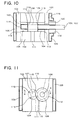
- the transfer members will be described with reference to Fig. 1 and Fig. 2.
- Fig. 1 shows an example of the process of the present invention in which a vertical polymerization reactor A and a horizontal polymerization reactor B are used.
- a reaction mixture is discharged quantitatively by a gear pump (2) from the vertical polymerization reactor A, introduced into curved pipes (4') and (4") through a curved pipe, passed through a curved pipe (4) and a valve (1) and introduced into the inlet of the horizontal polymerization reactor B.
- the reaction mixture is discharged from the outlet of the horizontal polymerization reactor B by a gear pump (2').
- Flanges (3) are used in this transfer route.
- Fig. 1 is a diagram typically showing an example of the arrangement of the valves (1), gear pumps (2), flanges (3) and flow passages (4) of the present invention.
- the types of polymerization reactors, the arrangement order of the transfer members and the number of transfer members of each type are not limited to those of Fig. 1.
- the transfer members including pipes in Fig. 1 are heated by a heating medium jacket.
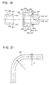
- Fig. 2 shows a flow of the reaction mixture when polymerization reactors I to IV are connected in series.
- the transfer members of the present invention can be arranged along the route shown by dotted lines in Fig. 2.
- the polymerization reactors I to IV may be of either a vertical or horizontal type.
- Fig. 2 shows four polymerization reactors but the number of polymerization reactors may be 2 to 5 and each of the polymerization reactors is maintained at a predetermined pressure and a predetermined temperature.
- the present invention makes it possible to obtain a high-quality polycarbonate which rarely produces a deteriorated product of a polymer and is used as a base material for an optical recording material by using (1) valves, (2) gear pumps, (3) flanges and (4) flow passages having the above structures and characteristic properties as transfer members.
- a process for producing a polycarbonate resin through the melt polycondensation of an aromatic diol compound and a carbonic acid diester compound wherein (1) valves, (2) gear pumps and (3) flanges used in the production process have the above structures and characteristic properties.
- a process for producing a polycarbonate resin through the melt polycondensation of an aromatic diol compound and a carbonic acid diester compound wherein at least one member out of (1) valves, (2) gear pumps and (3) flanges used in the production process has the above structure and characteristic properties.
- a process for producing a polycarbonate resin through the melt polycondensation of an aromatic diol compound and a carbonic acid diester compound wherein at least one member out of (1) valves, (2) gear pumps, (3) flanges and (4) flow passages used in the production process has the above structure and characteristic properties.
- aromatic polycarbonate as used herein means an aromatic polycarbonate obtained by the melt polycondensation of an aromatic diol compound and a carbonic acid diester as essential ingredients in the presence of an ester exchange catalyst such as one comprising an alkali earth metal compound, an alkali metal compound or a nitrogen-containing basic compound.
- aromatic diol compound examples include bis(4-hydroxyphenyl)methane, 2,2-bis(4-hydroxyphenyl)propane, 2,2-bis(4-hydroxy-3-methylphenyl)propane, 4,4-bis(4-hydroxyphenyl)heptane, 2,2-bis(4-hydroxy-3,5-dichlorophenyl)propane, 2,2-bis(4-hydroxy-3,5-dibromophenyl)propane, 1,1-bis(4-hydroxyphenyl)-3,3,5-trimethylcyclohexane, 4,4-(m-phenylenediisopropylidene)diphenol, bis(4-hydroxyphenyl)oxide, bis(3,5-dichloro-4-hydroxyphenyl)oxide, p,p'-dihydroxydiphenyl, 3,3'-dichloro-4,4'-dihydroxydiphenyl, bis(hydroxyphenyl)sulfone, resorcino
- Illustrative examples of the carbonic acid diester include diphenyl carbonate, ditolyl carbonate, bis(chlorophenyl)carbonate, m-cresyl carbonate, dinaphthyl carbonate, bis(diphenyl)carbonate, dimethyl carbonate, diethyl carbonate, dibutyl carbonate, dicyclohexyl carbonate and the like. Out of these, diphenyl carbonate is particularly preferred.
- the polycarbonate of the present invention may further contain an aliphatic diol such as ethylene glycol, 1,4-butanediol, 1,4-cyclohexane dimethanol or 1,10-decanediol; a dicarboxylic acid such as succinic acid, isophthalic acid, 2,6-naphthalenedicarboxylic acid, adipic acid, cyclohexanecarboxylic acid or terephthalic acid; or an oxyacid such as lactic acid, p-hydroxybenzoic acid or 6-hydroxy-2-naphthoic acid as required.
- an aliphatic diol such as ethylene glycol, 1,4-butanediol, 1,4-cyclohexane dimethanol or 1,10-decanediol
- a dicarboxylic acid such as succinic acid, isophthalic acid, 2,6-naphthalenedicarboxylic acid, adipic acid, cyclohe
- the alkali metal compound used as a catalyst is, for example, a hydroxide, bicarbonate, carbonate, acetate, nitrate, nitrite, sulfite, cyanate, thiocyanate, stearate, borohydride, benzoate, hydrogen phosphate, bisphenol salt or phenol salt of an alkali metal.
- alkali metal compound examples include sodium hydroxide, potassium hydroxide, lithium hydroxide, sodium bicarbonate, potassium bicarbonate, lithium bicarbonate, sodium carbonate, potassium carbonate, lithium carbonate, sodium acetate, potassium acetate, lithium acetate, sodium nitrate, potassium nitrate, lithium nitrate, sodium nitrite, potassium nitrite, lithium nitrite, sodium sulfite, potassium sulfite, lithium sulfite, sodium cyanate, potassium cyanate, lithium cyanate, sodium thiocyanate, potassium thiocyanate, lithium thiocyanate, sodium stearate, potassium stearate, lithium stearate, sodium borohydride, potassium borohydride, lithium borohydride, sodium phenyl borate, potassium phenyl borate, lithium phenyl borate, sodium benzoate, potassium benzoate, lithium benzoate, disodium hydrogen phosphate, dipotassium hydrogen phosphate,
- the alkali earth metal compound used as a catalyst is a hydroxide, acetate, nitrate, nitrite, sulfite, cyanate, thiocyanate, stearate, benzoate, hydrogenphosphate, bisphenol salt or phenol salt of an alkali earth metal.
- alkali earth metal compound examples include barium hydroxide, calcium hydroxide, strontium hydroxide, magnesium hydroxide, barium acetate, calcium acetate, strontium acetate, magnesium acetate, barium nitrate, calcium nitrate, strontium nitrate, magnesium nitrate, calcium salts, barium salts, strontium salts and magnesium salts of bisphenol A, calcium salts, barium salts, strontium salts and magnesium salts of phenol, and the like.
- the alkali metal compound or alkali earth metal compound as a catalyst is preferably used in such a proportion that the amount of an elemental alkali metal or alkali earth metal contained in the catalyst should be 1 x 10 -8 to 5 x 10 -5 equivalent, preferably 5 x 10 -7 to 1 x 10 -5 equivalent based on 1 mol of the aromatic diol compound.
- Illustrative examples of the nitrogen-containing basic compound as a catalyst include ammonium hydroxides having an alkyl, aryl or alkylaryl group such as tetramethyl ammonium hydroxide (Me 4 NOH), tetraethyl ammonium hydroxide (Et 4 NOH), tetrabutyl ammonium hydroxide (Bu 4 NOH), benzyltrimethyl ammonium hydroxide ( ⁇ -CH 2 (Me) 3 NOH) and hexadecyltrimethyl ammonium hydroxide; tertiary amines such as triethylamine, tributylamine, dimethylbenzylamine and hexadecyldimethylamine; and basic salts such as tetramethyl ammonium borohydride (Me 4 NBH 4 ), tetrabutyl ammonium borohydride (Bu 4 NBH 4 ), tetrabutyl ammonium tetraphenyl borate (
- the above nitrogen-containing basic compound is preferably used in such a proportion that the amount of ammonium nitrogen atoms contained in the nitrogen-containing basic compound should be 1 x 10 -5 to 5 x 10 -4 equivalent, more preferably 2 x 10 -5 to 5 x 10 -4 equivalent, particularly preferably 5 x 10 -5 to 5 x 10 -4 equivalent based on 1 mol of the aromatic diol compound.
- an alkali metal salt of a complex of the group 14 element of the periodic table or (b) an alkali metal salt of an oxoacid of the group 14 element of the periodic table as disclosed by JP-A 7-268091 may be used as the alkali metal compound catalyst as desired.
- the group 14 element of the periodic table is silicon, germanium or tin.
- the polycondensation reaction can be quickly and fully promoted by using the alkali metal salt of the above mentioned complex of the group 14 element as a polycondensation reaction catalyst. Further, an undesired side-reaction such as a branching reaction generated during the polycondensation reaction can be suppressed to a low level by using the above catalyst.
- the above polycondensation reaction catalyst is preferably used in such a proportion that the amount of an elemental alkali metal contained in the catalyst should be 1 x 10 -8 to 5 x 10 -5 equivalent, more preferably 5 x 10 -7 to 1 x 10 -5 equivalent based on 1 mol of the aromatic diol compound.
- At least one co-catalyst selected from the group consisting of oxoacids of the group 14 elements of the periodic table and oxides of the elements may be used in conjunction with the above catalyst as required in the polycondensation reaction of the present invention.
- a branching reaction which is readily initiated during the polycondensation reaction, the formation of foreign matter in an apparatus during molding and an undesired side-reaction such as a color difference can be effectively suppressed without impeding the capping reaction of a terminal and decreasing a polycondensation reaction speed by using the above co-catalyst in a specific proportion.
- the co-catalyst is preferably existent in such a proportion that the amount of the group 14 metal element of the periodic table contained in the co-catalyst should be 0.1 to 30 mols based on 1 mol (atoms) of the elemental alkali metal contained in the polycondensation reaction catalyst.
- the above catalytic system has such an advantage that a polycondensation reaction and a terminal capping reaction can be quickly and fully promoted by using these catalysts for the polycondensation reaction. It can also suppress an undesired side-reaction such as a branching reaction in the polycondensation reaction system to a low level.
- the temperature and the pressure for carrying out an ester exchange reaction between an aromatic diol compound and a carbonic acid diester compound are not particularly limited in the present invention. Any temperature and any pressure are acceptable if the reaction starts and a monohydroxy compound formed by the reaction is swiftly removed from the reaction system. However, it is the most common that, after the reaction is started at a temperature of 150 to 200°C and a pressure of 40,000 x 10 -6 to 13,333 x 10 -6 MPa, the reaction temperature is elevated and the reaction pressure is reduced as the molecular weight of a polycarbonate grows along with the proceeding of the reaction and the reaction is carried out finally at a temperature of 270 to 350°C and a pressure of 133 x 10 -6 MPa or less.
- the reaction at a temperature of 150 to 220°C and a pressure of 40,000 x 10 -6 to 13,333 x 10 -6 MPa when the viscosity average molecular weight (Mv) of a polycarbonate is 1,000 to 2,000, at a temperature of 180 to 240°C and a pressure of 20,000 x 10 -6 to 2,000 x 10 -6 MPa when Mv is 2,000 to 4,000, at a temperature of 200 to 250°C and a pressure of 13,333 x 10 -6 to 1,333 x 10 -6 MPa when Mv is 4,000 to 6,000, at a temperature of 220 to 280°C and a pressure of 4,000 x 10 -6 to 133 x 10 -6 MPa when Mv is 6,000 to 10,000, and at a temperature of 250 to 300°C and a pressure of 133 x 10 -6 MPa or less when Mv is more than 10,000.
- the unit of pressure used is absolute pressure throughout the specification unless otherwise stated.
- a stabilizer may be added to the polycarbonate obtained in the present invention.
- Known stabilizers are effectively used as the stabilizer used in the present invention.
- ammonium salts and phosphonium salts of sulfonic acid are preferred, and the above salts of dodecylbenzenesulfonic acid such as tetrabutylphosphonium dodecylbenzenesulfonate and the above salts of paratoluenesulfonic acids such as tetrabutyl ammonium paratoluenesulfonate are particularly preferred.
- Preferred sulfonic acid esters include methyl benzenesulfonate, ethyl benzenesulfonate, butyl benzenesulfonate, octyl benzenesulfonate, phenyl benzenesulfonate, methyl paratoluenesulfonate, ethyl paratoluenesulfonate, butyl paratoluenesulfonate, octyl paratoluenesulfonate, phenyl paratoluenesulfonate and the like. Out of these, tetrabutyl phosphonium dodecylbenzenesulfonate is the most preferred.
- the amount of the stabilizer is 0.5 to 50 mols, preferably 0.5 to 10 mols, more preferably 0.8 to 5 mols based on 1 mol of the polymerization catalyst selected from alkali metal compounds and/or alkali earth metal compounds.
- Equipment for carrying out the present invention is not particularly limited and the present invention may be carried out in a batch or continuous system.
- the batch system two reactors are generally connected in series, an agitator equipped with a distillator is used for the first reactor, and an agitator without distillator is used for the second reactor to carry out a reaction under different conditions.
- both reactors be connected by a pipe equipped with a valve, the reaction mixture of the first reactor be transferred to the second reactor without being exposed to the outside air, and a reaction be carried out to a desired degree of polymerization in the second reactor.
- two or more reactors are generally connected in series, adjacent reactors are connected by a pipe equipped with a valve, equipment comprising a pump for transferring a reaction mixture as required is used to supply raw materials and a catalyst to the first reactor continuously while the reactors are maintained under different conditions, and a polycarbonate having a desired degree of polymerization is discharged continuously from the final reactor.
- the above equipment must have a function to stop or branch a flow of the reaction mixture and valves installed in vessels and pipes for this purpose play an important role.
- Gear pumps, flanges and flow passages for transferring or discharging the reaction mixture must have an important function to obtain a high-quality polycarbonate.
- the polycarbonate is colored, is changed or is varried a deteriorated product called "three-dimensionally crosslinked gel" when it receives long-time heat history though the influence of oxygen is completely eliminated, unlike other polycondensation polymers such as polyethylene terephthalate. This reduces the quality of the obtained polycarbonate and causes a serious problem in optical application.
- reaction portion of the reaction mixture means a portion of the reaction mixture which deteriorates the quality of a polycarbonate product because a deteriorated product formed at a site where the continuous replacement of the reaction mixture hardly occurs is contained in the reaction mixture.
- sequence portion means “residence portion of the reaction mixture” throughout the specification.
- a ball valve, plug valve or T-shaped globe valve has been used to stop a flow of a reaction mixture in a straight portion of a pipe.
- valves have been selected from the viewpoints of a pressure loss generated in the pipe, pressure durability, vacuum resistance and the economy of equipment investment.
- the present inventors have found in the course of studies on the improvement of the quality of a polycarbonate product produced by an ester exchange method that the structure of a valve has a great influence upon the quality of a polycarbonate product and have conducted intensive studies on the structures of various valves.
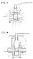
- a ball valve has such a structure that a passing fluid can flow when the inner space 2 of a ball 1 is opened in a flow direction "a" of the fluid as shown in Fig. 3 and its flow is stopped when the inner space 2 is not opened in the flow direction "a" of the fluid.
- the clearance 4 above and below the ball is shown in Fig. 3 but it also exists around side portions of the ball 1. Since the ball 1 slides over a sheet packing 5 while it contacts it during the operation of the valve, the surface of the seat packing 5 is apt to be chipped and generate powders. Particularly when a heat durability carbon packing is used as the seat packing 5, generated powders have a significant bad influence upon the quality of a product.
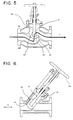
- This valve has such a structure as shown in Fig. 4 and is superior to a ball valve because it does not generate packing powders as it is not sealed with a seat packing unlike the above ball valve, its maintenance is easy as it does not use a seat packing having a shorter service life than the valve body and there is no residence portion as there is no clearance between a plug 11 and a valve body 13.
- the reaction mixture is cooped in the inner space 12 of the plug 11 and the cooped and retained reaction mixture is liable to deteriorate.
- the plug 11 To move the valve, the plug 11 must be turned after the plug is lifted to form a clearance (the plug itself is moved in a direction of the handle of the valve, that is, direction "b" in Fig. 4) because metal-to-metal sealing is effected for a gap between the valve body 13 and the plug 11.
- a space 14 which the reaction mixture enters is formed around the side surface of the plug and the reaction mixture residing in this portion is apt to deteriorate.
- it is difficult to maintain a vacuum atmosphere in the valve when the valve is moved the reaction mixture is liable to contact air outside the valve and deteriorate by oxidation, and the automation of the operation of lifting this plug is difficult.
- the present inventors have conducted studies on the structure and characteristic properties of a valve for improving the above problems of the prior art and efficiently obtaining a polymer which rarely produces a deteriorated product and has excellent quality in an industrial process for producing a polycarbonate. As a result, they have found that a high-quality polycarbonate which rarely produces the deteriorated product of the polymer can be obtained by using the following valve.
- valves having the following structure and performance are used in the production process.
- the expression "substantially no leakage under a vacuum pressure of 40,000 x 10 -6 MPa or less” means that the leakage of gas from the outside of the valve is 120 x 10 -6 MPa ⁇ l/h or less based on 1 liter of the inner capacity of the valve when the ultimate vacuum degree of the valve is 13.3 x 10 -6 MPa.
- the measurement may not be easy because the inner capacity of the valve is too small.
- 3 x 10 -5 ACC/S or less can be used instead.
- the measurement method is as follows.
- the measurement of the leakage of gas is carried out by sucking gas inside the value by a vacuum pump to reduce the pressure inside the value to 13.3 x 10 -6 MPa, stopping suction and confirming after one hour that the pressure inside the value is lower than a predetermined pressure.
- the capacity of the value is 1 litter, for example, the value stands the test the pressure inside the value is lower than 133 x 10 -6 MPa one hour after the suction of the vacuum pump is stopped.
- a helium leak detector is connected to the value and the vacuum pump, the value is covered with a bag while suction by the vacuum pump is continued, helium is blown into the inside of bag from the outside, and the leakage of helium into the inside of the value is measured by the helium leak detector. If the leakage of the detected helium is 3 x 10 -5 ACC/S or less, the value stands test.
- the DLMS-TP3E of Nippon Shinku Gijutsu Co., Ltd. may be used as the helium leak detector.
- ACC/S means atm ⁇ cc/sec which indicates a volume at 1 atm. and normal temperature as the leakage of helium per unit sec.
- the valve is desired to have no leakage because it is the outside air, especially oxygen entering the reactor that deteriorates the reaction mixture and has a significant bad influence upon the quality of a polycarbonate product. Since the valve has a relatively complex structure that it has a movable portion, such air easily enters the valve.
- reaction mixture Since the reaction mixture is oxidized as soon as it is exposed to oxygen, it is colored or deteriorated, thereby greatly reducing the quality of the polycarbonate. Therefore, it is important to prevent the reaction mixture from being exposed to oxygen contained in the air and it is desired to improve airtightness and place the gland portion of the valve in 98 vol% or more of nitrogen atmosphere.
- liquid contact portion is made from a material having corrosion resistance against a monohydroxy compound formed by a reaction between the aromatic diol compound and the carbonic acid diester compound
- a seat portion of the valve is preferably made from stellite such as STELLITE FACE#6 and the valve body is preferably made from stainless steel such as SUS304, SUS304L, SUS316, SUS316L, SUS630, SCS13, SCS14, SCS16 or SCS19, specified by JIS.
- any material is acceptable as the material of the gland packing if it has required sealing properties.
- a coil packing prepared by knitting asbestos, carbon fibers, polytetrafluoroethylene (PTFE) fibers, aramide fibers or expanded graphite yarn into a predetermined shape with a rectangular cross section or the like and impregnating with PTFE, graphite or lubricating oil and/or a packing molded into a ring form with a V-shaped cross section are/is preferably used.
- PTFE polytetrafluoroethylene
- a spiral wound gasket prepared by placing a filler such as asbestos, inorganic paper, expanded graphite or PTFE upon a metal hoop having a V-shaped cross section and spirally winding the laminate under tension is preferably used.
- the Y-shaped globe valve is such as shown in Fig. 6 that a pipe and the stem of the valve are arranged into the form of letter Y.
- the stem can move not to disturb a flow of a reaction mixture in the pipe as much as possible.
- the present inventors have paid attention to a globe valve as a valve which has a favorable influence upon the quality of a polycarbonate product.
- the problem of the reaction mixture residing in the above ball valve and plug valve and a residence portion in the clearance is slightly improved.
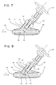
- the T-shaped globe valve has such a structure as shown in Fig. 5, it has a disk 32 having a larger diameter than that of a stem 31 at the end of the stem, a large residence space 33 is formed behind the disk 32, the reaction mixture in this residence space 33 becomes a residence portion which rarely receives the influence of a flow of a fluid (an upper portion of the residence space 33 of Fig.
- the cross section of the flow passage in the valve is greatly changed by the existence of a seat 34 which receives the disk 32, and the flow of the fluid greatly changes its direction as shown by an arrow "c". Therefore, it has been found that the T-shaped globe valve has such a problem that the flow is disturbed, thereby producing a great pressure loss, and that this problem becomes more serious as the viscosity of the fluid increases.
- a disk 42 is provided at the end of a stem 41 which is arranged at an angle to a flow direction of a reaction mixture, a flow of the passing fluid shown by an arrow "d" is stopped by contact between the disk 42 and a seat 43 provided in a fluid passing portion, the stem 41 and the disk 42 are moved in the direction of a handle 44 by turning the handle 4 in a certain direction, the flow of the passing fluid shown by the arrow "d” is resumed, the volume of a space 45 behind the disk 42 is reduced by the moving stem 41 and disk 42 at this point, the disturbance of the flow of the reaction mixture is smaller than that of an ordinary T-shaped globe valve, and a pressure loss is small when the fluid passes through this portion, whereby the retained reaction mixture has small chances of going into the flow of the reaction mixture incidentally and the residence portion (portion corresponding to the space 33 in Fig. 5) shown by the space 45 formed behind the disk is small. Therefore, it has been found that this Y
- valve When the valve has substantially no leakage under a vacuum pressure of 40,000 x 10 -6 MPa or less and its liquid contact portion is made from a material having corrosion resistance against a monohydroxy compound formed by a reaction between the aromatic diol compound and the carbonic acid diester compound, it has been verified that the valve can stand long-time use of 1 year or more and produce good results in the maintenance of the quality of a polycarbonate product as a device for producing a polycarbonate.
- the residence portion formed in these valves causes the deterioration of a polycarbonate such as coloration, crosslinking or gelation and may exert a non-negligible influence upon product quality. This is an especially serious problem to be solved for a polycarbonate which is liable to reside and deteriorate in the residence portion.
- the present inventors have tackled with the further improvement of the Y-shaped globe valve through studies on these valves and have found that a Y-shaped globe valve having the following features can solve the above problems completely.
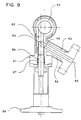
- FIG. 7 A preferred example of the valve of the present invention is shown in Fig. 7.
- the example shown in Fig. 7 is mere an embodiment of the present invention, and it should be understood that the present invention is not limited by this figure.
- reference numeral 51 denotes a valve body. This valve body 51 is covered with a heating medium jacket 52 therearound. A reaction mixture inlet port 54 is provided at one end of the tubular portion 53 of the valve body 51 and a reaction mixture outlet port 55 is provided at the other end. A stem 56 is provided in a center portion of the valve body 51 and can be slid vertically by operating a handle 58 while it is sealed with a gland packing 57. A flow of a fluid is cut off when an end portion of the stem 56 contacts a seat 60. Closing the valve indicates this state and is shown by a solid line in Fig. 7. Meanwhile, fully opening the valve indicates the opposite state and is shown by a broken line in Fig. 7. The valve is fully opened to flow a reaction mixture.
- the valve body 51 is made from the above corrosion-resistant material and the stem 56 is also made from the same material. Since they are made from the same material, even if the temperatures of the valve body 51 and the stem 56 rise, the clearance between them is maintained at a fixed value, rarely becomes larger than a designed value or suppresses contact between them because the coefficient of thermal expansion of the valve body 51 and the stem 56 are the same. This is preferred from the view point of reducing the residence portion.
- the seat 60 is made from the above sealing material such as STELLITE FACE#6 to prevent the seizure of the valve body 51 and the stem 56 and to enable sealing properties to be retained for a long time.
- Reactors are connected by a pipe and the valve is generally installed in the pipe.
- the reaction mixture inlet port 54 and the reaction mixture outlet port 55 are butt welded (butt welded joint) to the pipe.
- reference notation 54 denotes the reaction mixture inlet port and 55 the reaction mixture outlet port. It merely means that this arrangement is very common, and the reaction mixture inlet port and the reaction mixture outlet port may be installed in opposite directions according to the actual installation space.
- the reaction mixture is supplied continuously from the reaction mixture inlet port 54 by the valve thus constituted.
- the valve When the valve is opened, the reaction mixture is discharged to the outside of the system from the reaction mixture outlet port 55.
- the reaction mixture is shut off and does not flow to the reaction mixture outlet port 55.
- the above Y-shaped globe valve according to the present invention has such a great improvement that a residence portion behind the disk is eliminated to remove a space behind the disk because it has no disk at the end of the stem and a portion into which the stem is inserted of the valve body and the stem have substantially the same thickness.
- the expression "have substantially the same thickness” means that the thickness of the stem is smaller than that of the portion into which the stem is inserted of the valve body by a clearance required for the stem to slide in the valve body.
- the difference between the outer diameter of the stem and the inner diameter of the portion into which the stem is inserted of the valve body is preferably set to 2 mm or less. The difference is more preferably 1 mm or less, much more preferably 0.5 mm or less.
- the cross section of the portion into which the stem is inserted of the valve body is desirably ⁇ 15 % of the cross section of a portion through which the reaction mixture flows of the tubular portion to suppress the turbulent flow of the reaction mixture. It is more desirably the same as the inner diameter of the tubular portion.
- a spacer 62 having a smooth curved surface so as not to disturb the flow line of the running reaction mixture is provided at the end of the stem 56.
- An end of the spacer 62 is smoothly connected to a portion 59 on a downstream side of the spacer 62, which is the inner surface of an upper portion of a tubular portion 53, when the valve is fully opened and the fluid flows in a direction "e" of Fig. 8. That is, the end of the spacer 62 which is the end portion of the stem of the Y-shaped globe valve and the inner surface of the upper portion of the tubular portion of the valve have a curved surface so that they can form a smooth curved surface when the valve is opened.
- the curved surface is shown by a broken line in Fig. 8.
- Other numerals in Fig. 8 signify the same elements as those of Fig. 5.
- the spacer 62 is provided at the end portion of the stem 56 to form a smooth curved surface not to disturb the flow of the reaction mixture.
- the formation of this smooth curved surface reduces the residence portion without disturbing the flow of the fluid as much as possible and can prevent the deteriorated polymer which caused in the residence portion which still exists in the present invention from flowing into the flow of the fluid by the turbulent flow of the fluid.
- the Y-shaped globe valve shown in Fig. 7 does not have a structure that provides a smooth curved surface so as not to disturb the flow of the reaction mixture when it is fully opened. Therefore, the present invention shown in Fig. 8 has been accomplished based on the discovery of a new fact that this structure is one of the causes of deteriorating the quality of a polycarbonate product.
- the expression "formation of this smooth curved surface” as used herein means the formation of a substantially smooth curved surface.
- the diameter of the spacer 62 is made a little smaller than the diameter of the stem 56 to realize perfect contact between the stem 56 and the seat 60 when the valve is closed. Therefore, when the valve is closed, 1 to 0.5 mm space 63 is formed between the spacer 62 and the valve body 51.
- the formation of a gentle curved surface in the present invention comprehends a case where the smooth curved surface becomes partly discontinuous by the space 63.
- a clearance is required between the stem and the valve body for the stem to slide in the structure of the valve.
- an O ring (denoted by notation 61 in Fig. 7 and Fig. 8) having excellent heat durability and corrosion resistance in this portion is more effective so that the stem can slide substantially in contact with the inner surface of the O ring. This can effectively prevent a retained product of the fluid from flowing into the reaction mixture, which can take place in the clearance as well.
- a preferred example of the O ring used for this purpose is an O ring made from a perfluoro elastomer (for example, Kalrez of Du Pont Dow Elastomers.)
- the Y-shaped globe valve of the present invention is uniformly heated by a heating medium jacket, electric heater or the like.
- a heating medium jacket to integrate the heating medium jacket with the valve body as shown in Fig. 5 is more preferred than to cover the Y-shaped globe valve of the present invention with the heating medium jacket from the viewpoint of uniform heating.
- the Y-shaped globe valve of the present invention is relatively large in size, it is preferred to provide a baffle plate in the heating medium jacket or to increase the number of the flow passages of a heating medium so as to uniformly heat the Y-shaped globe valve of the present invention.
- the surface roughness of the inner portion of the liquid contact portion is preferably 10 ⁇ m or less. This surface roughness is 10 ⁇ m or less, preferably 3.3 ⁇ m or less in terms of Rmax.
- the liquid contact portion is finished with a buff of #200 or more, has a gloss higher than that of a standard sample and is free from pin holes, circular fine streaks, scratches, level differences and dimples. More preferably, the liquid contact portion has a surface roughness of 1.6 ⁇ m or less in terms of Rmax. That is, it is finished with a buff of #300 or more, or subjected to finishing such as honing, super finishing, lapping, liquid honing, chemical polishing or electrolytic polishing. In the present invention, Rmax was measured in accordance with JIS B0601-1982.
- the term "heat durability” as used herein means that the airtightness and pressure durability of the valve are higher than required air tightness and pressure durability during operation even when the strength of the material at a high temperature becomes lower than a value at normal temperature and any problem does not arise in its use even when the valve receives force such as the thermal expansion of its material.
- the heat durability temperature of the equipment is preferably set to a range of 150 to 350°C according to its operation conditions.
- the heat durability temperature is higher than 350°C, the material is limited, its processing becomes difficult, the obtained valve becomes expensive, a wide clearance must be formed between the parts of the valve to eliminate the influence of the thermal expansion of the material constituting the valve, and the residence and deterioration of the reaction mixture in this portion readily occur disadvantageously.
- the inside of the valve of the present invention preferably has a pressure durability of 0.1 MPa or more.
- pressure durability of 0.1 MPa or more means that the valve does not leak a liquid or gas to the outside of the valve or to a secondary side and does not cause any problem at all in its use whether it is opened or closed, even when a predetermined pressure of 0.1 MPa or more is applied to the inside of the valve, when a side which is shut off by the stem and to which pressure is applied when the valve is closed is called “primary side” and a side to which pressure is not applied is called “secondary side”.
- the pressure durability is generally in the range of 0.1 to 30 MPa.
- the pressure durability of the primary side against the secondary side may be made lower than pressure durability against the outside of the valve.
- Means of connecting the Y-shaped globe valve of the present invention to the pipe or the like preferably has the same pressure durability, corrosion resistance and surface roughness for the liquid contact portion as those of the Y-shaped globe valve of the present invention.
- the connections device may be a flange, welding, grayloc or the like.
- Power for opening and closing the Y-shaped globe valve of the present invention may be human power, air pressure, electricity, hydraulic pressure or any other which can move the stem.
- the stem When the stem is moved by power, it is desired to incorporate a fail-safe mechanism by which the process becomes safe even when abnormality such as a power failure or disconnection occurs.
- the Y-shaped globe valve of the present invention is installed in the pipe of the polycarbonate production equipment, between a vessel and the pipe, or in a branch of the pipe or the vessel.
- the Y-shaped globe valve may be used as a sampling valve for sampling the reaction mixture in the pipe by taking it out to the outside of the pipe, or in conjunction with a valve of another type.
- the Y-shaped globe valve is not limited to examples shown in Figs. 6, 7 and 8 but it is needless to say that it is what is generally used as a Y-shaped globe valve. For example, as shown in Fig.
- a Y-shaped globe valve at a location where the flow of the reaction mixture in a direction perpendicular to the plane of the sheet changes its direction to a downward direction and the liquid flows obliquely downward thereafter.
- Numerals in Fig. 9 denote the same elements as those of Fig. 7 and Fig. 8.
- the material used for the Y-shaped globe valve of the present invention is preferably subjected to a heat treatment when the influence of residual stress upon the material at high temperatures is taken into consideration.
- bellows are used to seal a gland portion of the valve.
- corrosion resistance becomes a problem for the reasons of not only the bad influence of the dissolved material such as the prevention of a reaction or the coloration of the polycarbonate but also the formation of a roughened surface probably by corrosion.
- the material having corrosion resistance is stainless steel and the liquid contact portion is subjected to mechanical finishing such as buffing or to chemical finishing such as electrolytic polishing.
- the pump used in the production process of a polycarbonate is used at high temperatures under high vacuum. Since the viscosity of the reaction mixture rises to an extremely high level, generally 200 Pa ⁇ S to 1,000 Pa ⁇ S, which differs according to reaction conditions, along with the proceeding of the above reaction (reaching completion), when the reaction mixture is transferred by a pipe, the pressure of the pump must be raised in accordance with resistance (pressure loss) generated in the pipe. For this purpose, a gear pump has been generally used in the prior art.
- the gear pump of the prior art is made from tool steel having small coefficient of thermal expansion and excellent abrasion resistance, it is inferior in corrosion resistance against the raw materials of the reaction mixture, the material of the gear pump dissolves, the coloration of the reaction mixture occurs, and the dissolved material hinders the activity of a catalyst and reduces the reaction rate.
- reaction mixture as a product is used for the purpose of lubricating the gear, the reaction mixture which is exposed to high temperatures by heat generated by the gear and high shear for a long time deteriorates and returns into the product, thereby causing deterioration such as coloration, crosslinking or gelation. Thus, a non-negligible influence is exerted upon product quality.
- a residence portion is formed between a bushing which is the shaft end portion of the gear and the bearing of the gear and a cover plate (front plate and back plate).
- a bushing which is the shaft end portion of the gear and the bearing of the gear and a cover plate (front plate and back plate).
- section of the pipe at the inlet portion of the reaction mixture is generally circular
- an upper portion of the gear generally has a rectangular shape, consequently the sectional shape of the inlet portion of the reaction mixture must be sharply changed to connect these sections having different shapes. Therefore, the residence portion is formed due to the difficulty of machining. Since the sealing of a fixed portion (not driven portion) is metal-to-metal sealing, a residence portion is formed when the gear pump is badly assembled.
- the present inventors have conducted studies on the structure and properties of a gear pump for improving the problem of the prior art and efficiently obtaining a high-quality polymer which rarely produces a deteriorated product in the industrial production process of a polycarbonate. As a result, it has been found that a high-quality polycarbonate which rarely produces a deteriorated product of a polymer can be obtained by using the following gear pump.
- gear pump which has a heat durability of 150° C or more, substantially no leakage under a vacuum pressure of 40,000 x 10 -6 MPa, a pressure durability of 0.1 MPa or more and a delivery pressure of 1 MPa or more, whose liquid contact portion is made from a material having corrosion resistance against a monohydroxy compound formed by a reaction between the aromatic diol compound and the carbonic acid diester compound, which can discharge a reaction mixture under a vacuum pressure of 40,000 x 10 -6 MPa or less, and which has such a structure that the reaction mixture for lubricating contact portions among a gear, a shaft and other gear pump members is discharged to the outside of the pump without returning into the pump.
- Equipment comprising the gear pump of the present invention is not particularly limited and the present invention may be carried out in a batch or continuous system.
- a batch system two polymerization reactors are generally connected in series, a agitator equipped with a distillator is used for the first reactor, and a agitator without distillator is used for the second reactor to carry out a reaction under different conditions.
- both reactors be connected by a pipe equipped with a valve, equipment comprising a gear pump for transferring a reaction mixture as required be used to transfer the reaction product of the first reactor to the second reactor without exposing the reaction mixture to the outside air, and a reaction be carried out to a desired degree of polymerization in the second reactor.
- two or more reactors are generally connected in series, adjacent reactors are connected by a pipe equipped with a valve, equipment comprising a gear pump for transferring a reaction mixture as required is used to supply raw materials and a catalyst to the first reactor continuously while the reactors are maintained under different conditions, and a polycarbonate having a desired degree of polymerization is discharged continuously from the final reactor.
- the polycarbonate is colored or produces a deteriorated product called "three-dimensionally crosslinked gel" when it receives long-time heat history though the influence of oxygen is completely eliminated. This reduces the quality of the obtained polycarbonate and causes a serious problem in such application that requires high quality, for example, optical application.
- the present inventors have conducted intensive studies to solve this problem, have found that a gear pump to which importance was not attached before has a great influence upon the dead space of the whole equipment and have succeeded in greatly improving the quality of a polycarbonate obtained by melt polymerization by using a gear pump having a specific structure.
- a pump for transferring the reaction mixture is such as shown in Fig. 10.
- the term "heat durability" as used herein means that the airtightness and pressure durability of the gear pump at high temperatures are higher than required air tightness and pressure durability during operation and any problem does not arise in its use even when the gear pump receives force such as the thermal expansion of its material.
- the heat resistance temperature of the equipment is preferably set to a range of 150 to 350°C according to its operation conditions.
- the heat resistance temperature is higher than 350°C, the material is limited, its processing becomes difficult, the obtained gear pump becomes expensive, a wide clearance must be formed between the parts of the gear pump to eliminate the influence of the thermal expansion of the material constituting the gear pump, and the residence and deterioration of the reaction mixture in this portion readily occur disadvantageously. Since there is a case where a bolt for tightening the parts constituting the gear pump is loosened by thermal expansion, tightening force is preferably increased according to use temperature.
- the expression "substantially no leakage under a vacuum pressure of 40,000 x 10 -6 MPa or less” means that the leakage of gas from the outside of the gear pump is 120 x 10 -6 MPa ⁇ l/h or less based on 1 liter of the inner capacity when the ultimate vacuum degree of the gear pump is 13.3 x 10 -6 MPa.
- the measurement may not be easy because the inner capacity of the gear pump is too small.
- 3 x 10 -5 ACC/S or less can be used instead.
- the measurement method is as follows.
- the measurement of the leakage of gas is carried out by sucking gas inside the gear pump by a vacuum pump to reduce the pressure inside the gear pump to 13.3 x 10 -6 MPa, stopping suction and confirming after one hour that the pressure inside the gear pump is lower than a predetermined pressure.
- the capacity of the gear pump is 1 liter, for example, the gear pump stands the test if the pressure inside the gear pump is lower than 133 x 10 -6 MPa one hour after the suction of the vacuum pump is stopped.
- a helium leak detector is connected to the gear pump and the vacuum pump, the gear pump is covered with a bag while suction by the vacuum pump is continued, helium is blown into the inside of the bag from the outside, and the leakage of helium into the inside of the gear pump is measured by the helium leak detector. If the leakage of the detected helium is 3 x 10 -5 ACC/S or less, the gear pump stands the test.
- the DLMS-TP3E of Nippon Shinku Gijutsu Co., Ltd. may be used as the helium leak detector.
- ACC/S means atm ⁇ cc/sec which indicates a volume at 1 atm. and normal temperature as the leakage of helium per unit sec.
- the outside of the gear pump is preferably placed in 98 vol% or more of an nitrogen gas atmosphere. Stated more specifically, this is often carried out by blowing from the outside nitrogen gas into a portion where the interior portion and the exterior portion of the gear pump are separated from each other by a sealing portion, such as a drive shaft seal part and a joint between a front plate and a gear case.
- a sealing portion such as a drive shaft seal part and a joint between a front plate and a gear case.
- the expression "pressure durability of 0.1 MPa or more” means that the gear pump does not leak a liquid or gas to the outside thereof and does not cause any problem at all in its use even when a predetermined pressure of 0.1 MPa or more is applied to the inside of the gear pump.
- the pressure durability is generally in the range of 0.1 to 30 MPa.
- liquid contact portion is made from a material having corrosion resistance against a monohydroxy compound formed by a reaction between the aromatic diol compound and the carbonic acid diester compound.
- the material is desirably stainless steel specified by JIS such as SUS304, SUS304L, SUS316, SUS316L, SUS630, SCS13, SCS14, SCS16, SCS19, SUS440C, SUS420J2 or SCS2, alloy tool steel specified by JIS such as SKS or SKD, high-speed tool steel such as SKH, nitride steel, plating such as Cr or Ni, stellite face finished or carbon steel lined by a hot isotactic press (HIP) method. Out of these, stainless steel is particularly preferred.
- JIS such as SUS304, SUS304L, SUS316, SUS316L, SUS630, SCS13, SCS14, SCS16, SCS19, SUS440C, SUS420J2 or SCS2
- alloy tool steel specified by JIS such as SKS or SKD
- high-speed tool steel such as SKH, nitride steel
- plating such as Cr or Ni
- the gear, shaft, bushing and body may be made from the same material or different materials but they are preferably made from the same material so as to maintain a clearance between parts formed by thermal expansion at a fixed value from the viewpoints of the stability of the flow rate of a liquid, high delivery pressure and a reduction in dead space.
- the material used for the gear pump is preferably subjected to a heat treatment when the influence of residual stress at high temperatures is taken into consideration.
- the gear pump of the present invention is substantially pulseless.
- substantially pulseless means that a change in the flow rate of the reaction mixture discharged by the gear pump is ⁇ 5 % or less, preferably ⁇ 1 % or less, more preferably ⁇ 0.5 % or less of a planned predetermined flow rate.
- the term "delivery pressure” means the pressure of the reaction mixture discharged by the gear pump and this pressure is limited by the viscosity of the reaction mixture used. This is because, when the viscosity is low, the delivery pressure becomes high and the reaction mixture flows backward to the inlet side from the outlet side of the gear pump through a clearance between the gear and the gear, a clearance between the gear and the bushing and a clearance between the gear and the body (that is, a back flow).
- the delivery pressure is limited to about 1 MPa
- the delivery pressure is limited to about 7 MPa
- the viscosity is more than 1 Pa ⁇ S
- the delivery pressure is limited to about 7 to 30 MPa.
- the expression "can discharge the reaction mixture under a vacuum pressure of 40,000 x 10 -6 MPa or less” means that the gear pump can transfer the reaction mixture pulseless at a predetermined flow rate and a predetermined delivery pressure even when the pressure at the inlet side of the gear pump is 40,000 x 10 -6 MPa or less.
- this is an important function in the production of a polycarbonate where a reaction is carried out under vacuum.
- liquid contact portion means an inside portion contacting the reaction mixture of the gear pump.
- the portion includes not only a portion which directly contacts the flow of the reaction mixture but also a portion which the reaction mixture used for lubrication contacts or the reaction mixture may enter.
- the expression "the surface roughness of the liquid contact portion is 10 ⁇ m or less” means that the surface roughness is 10 ⁇ m or less in terms of Rmax.
- the surface roughness is preferably 3.3 ⁇ m or less in terms of Rmax.
- the liquid contact portion is finished with the same finishing method illustrated in the above item of (1) value.
- a groove is formed in the bushing of the gear pump of the present invention for the lubrication of the gear so that the reaction mixture on the outlet side is caused to flow between the gear and the bushing and between the shaft and the bushing for lubrication. Since the reaction mixture used for lubrication is deteriorated by the reception of high temperatures and high shearing force in many cases, it is important to discharge this reaction mixture to the outside as much as possible and not to return it into the flow of a product.
- the gear pump It is preferred to heat the gear pump uniformly with a heating medium jacket, electric heater or the like.
- a heating medium jacket to integrate the heating medium jacket with the gear pump is more preferred than to cover the gear pump with the heating medium jacket from the viewpoint of uniform heating.
- the gear pump is relatively large in size, it is preferred to provide a baffle plate in the heating medium jacket or to increase the number of the flow passages of a heating medium so as to uniformly heat the gear pump.
- a flange is used to connect the gear pump, it is desired to provide a jacket for circulating the heating medium in the flange.
- Any means may be used to connect the gear pump of the present invention to the pipe or the like if it has the same pressure durability, corrosion resistance and surface roughness for the liquid contact portion as those of the gear pump.
- it is a flange, welding, grayloc or the like.
- An electric motor is generally used to drive the gear pump of the present invention.
- a flexible joint is generally used to connect a drive source to the gear pump and desirably can absorb the eccentricity of a drive shaft caused by the thermal expansion of the gear pump or the like.
- An upper limit of the current value of the motor or torque upper limit value is set to protect the gear pump when a metal piece bites the gear during the operation of the gear pump or when abnormal torque is applied to the gear by the deterioration or solidification of the reaction mixture in contact portions among the gear, the shaft and other gear pump members.
- the current value of the motor reaches the upper limit, the motor is stopped, or a shear pin or torque limiter is used to disconnect the drive source from the gear pump at a value larger than a predetermined torque value.
- the shaft seal of gear pump of the present invention is used to prevent the reaction mixture inside the gear pump excluding the reaction mixture used for lubrication from contacting the outside when the drive source for driving the gear and shaft is connected to the gear pump.
- Any shaft seal is acceptable if it has this function during operation, as exemplified by a mechanical seal, gland packing, sealing coupler, metal seal, ring seal, labyrinth seal, viscous seal and the like.
- the shaft seal can be used even when it does not contact the drive source.
- the connection style of the drive source to the gear pump is not limited to one.
- a scraping blade is preferably provided at a shaft end portion (end portion of the shaft) of the gear pump of the present invention to prevent the reaction mixture from residing in the shaft end portion.
- the scraping blade may have any shape if it has a function to remove the reaction mixture from the shaft end portion.
- the scraping blade is, for example, a scraper, propeller, screw or the like. Considering production ease and the work efficiency of washing or the like, a simple shape is preferred.
- the bushing is preferably fixed to the cover plate (front plate or back plate).
- Fixing means is not particularly limited but may be a bolt, welding or the like.
- the flow passage of the reaction mixture at the inlet port of the gear pump of the present invention that is, the flow of the reaction mixture at an inlet port portion of the reaction mixture is preferably smooth to prevent the flow line of the reaction mixture from being disturbed.
- the restriction angle of the flow passage is 45° or less in terms of vertical angle.
- the flow passage of the reaction mixture has substantially no level differences except for a required portion for supplying the fluid.
- the level difference of the required portion for supplying the fluid is the level difference of gear teeth.
- the expression "has substantially no level differences" means that an end portion is chamfered 2 mm or less, preferably 0.5 mm or less, more preferably 0.1 mm or less.
- the sealing of the fixed portion is the sealing of a gap between parts excluding the shaft and the gear which are movable portions of the gear pump.
- a gap between the front plate and the gear case, a gap between the back plate and the gear case, a gap between the bushing and the cover plate, and a gap between the pipe and the gear pump are sealed up.
- This sealing is metal-to-metal sealing which is effected by surface finishing these parts and making them parallel to each other or sealing with a liquid packing.
- the surface finish is preferably 25 ⁇ m or less, more preferably 6.3 ⁇ m or less in terms of Rmax.
- Metal-to-metal sealing is generally used but other sealing such as sealing with a liquid packing may be used.
- an hollow metal O ring is preferably used.
- the hollow metal O ring has such an advantage that, when a hollow metal O ring is used as a seal, even if vacuum sealing and also metal-to-metal sealing are insufficient, the reaction mixture does not leak to the outside of the gear pump from the hollow metal O ring, thereby making it possible to minimize a dead space formed in a portion where the reaction mixture leaks.
- the hollow metal O ring is desirably placed near the liquid contact portion of the reaction mixture as much as possible.
- reference notation 102 denotes a gear case.
- This gear case 102 is connected to an unshown drive unit which is located on a drive shaft seal 112 side of a driving shaft 106 and a follow shaft 107 (the drive shaft seal side of the driving shaft 106 and the follow shaft 107 is called “drive side” and the opposite side is called “counter-drive side” hereinafter).
- a front plate 101 is attached to the drive side of the gear case 112 and a back plate 103 is attached to the counter-drive side of the gear case 112 to form a body together with the gear case 102.
- This body is covered with a heating medium jacket 105 therearound.
- a reaction mixture inlet port 110 is formed at one end of the gear case 102 and a reaction mixture outlet port 111 is formed at the other end of the gear case 102.
- the driving shaft 106 is installed in the gear case 102 supported by a bushing 104 and provided with a gear 108.
- the driving shaft 106 is connected to the unshown drive unit on the drive side, and the gear 108 and the bushing 104 are sealed with the drive shaft seal 112 and separated from the outside of the gear pump.
- a gear 109 is engaged with the gear 108 (see Fig. 11) and attached to the follow shaft 107 supported by the bushing 104 like the gear 108.
- the gear 108 turns in a direction "a”
- the gear 109 engaged with the gear 108 turns in a direction "b”
- the reaction mixture from the reaction mixture inlet port 110 enters the valley portions of the gears 108 and 109 and rotates together with the gears 108 and 109 while it contacts the inner wall of the gear case 102, is forced out of the valley portions of the gears 108 and 109 when the gears 108 and 109 engage with each other on the reaction mixture outlet port 111 side and is supplied to the reaction mixture outlet port 111.
- Metal-to-metal sealing is effected for a gap between the front plate 101 and the gear case 102 and a gap between the back plate 103 and the gear case 102.
- metal-to-metal sealing may be insufficient in preventing leakage to the outside of the gear pump. Therefore, an O ring 113 is used for sealing.
- the O ring 113 serves as a seal for preventing the reaction mixture from leaking to the outside if metal-to-metal sealing should lose its effect owing to some trouble or the like.
- the bushing 104 has a lubricating groove 117 which serves as the flow passage of the reaction mixture as shown in Fig. 13 so that the reaction mixture itself functions as a lubricant for lubricating sliding surfaces 119 between the bushing 104 and the gear 108 and between the bushing 104 and the gear 109 and interfaces between the bushing 104 and the driving shaft 106 and between the bushing 104 and the follow shaft 107 and then is discharged to the outside of the gear pump through an exhaust groove 118.
- reaction mixture for lubrication spreads to a lubricating reaction mixture inlet port 121 (shown by a slant line), passes through the lubricating groove 117 and flows in a direction "c" shown by an arrow.
- the “contact portions among the gear, the shaft and other gear pump members” denote portions shown by bold lines in Fig. 10.
- the word “contact” as used herein does not always mean direct contact but means that the reaction mixture generally lies in these portions as a lubricant.
- means of discharging the reaction mixture used for lubrication to the outside of the system is not particularly limited.
- the means may be an exhaust port formed in the front plate or the back plate.
- the bushing 104 is fixed to the front plate 101 and to the back plate 103 by a bushing fixing bolt 115 as shown in Fig. 11 and Fig. 12 and sealed with an O ring 116 to prevent the reaction mixture inside from leaking to the outside of the gear pump or the outside air from entering the gear pump.
- a scraper 114 having straight thin protrusions is provided at an end portion on the counter-drive side of the driving shaft 116 and both end portions of the follow shaft 107 as shown in Fig. 10 so that the reaction mixture at the end portions of the shafts is stirred by the rotation of the shafts, is prevented from residing in these end portions and can be discharged to the outside smoothly.
- the front plate 101, the gear case 102 and the back plate 103 are preferably made from stainless steel such as SUS420J2, and the driving shaft 106, the follow shaft 107 and the gears 108 and 109 are preferably made from the same material.
- An advantage obtained by making elements from the same material is that even when the temperature of the gear pump is elevated to the operation temperature, a clearance between them is maintained at the same value as that at room temperature because they have the same coefficient of thermal expansion, thereby making it possible to maintain the clearance in the gear pump at a design value. This can prevent the formation of a dead space caused by an increase in the size of the clearance, an increase in the amount of generated heat due to a reduction in the size of the clearance and the gear pump from losing its function when it contacts another element.
- Reactors are connected by a pipe and the gear pump is installed in the pipe.
- the reaction mixture inlet port 110 and the pipe are connected by a flange and the reaction mixture outlet port 111 and the pipe are also connected by a flange, and a metal O ring is used for sealing.
- the metal O ring used is preferably surface plated to prevent seizure. It is plated with nickel or silver, for example.
- the flow passage of the reaction mixture at the reaction mixture inlet port 110 is restricted at an vertical angle of 20° and is used to supply the reaction mixture to the gear portion. That is, the restriction angle of the flow passage at the reaction mixture inlet port of the gear pump is 20°.
- the cross section of a connection pipe is generally circular and the cross section of the reaction mixture inlet port formed by the gear 108, the gear 109 and the gear case 102 of the gear pump is rectangular.
- This restriction angle is preferably as smooth as possible to prevent the formation of a dead space by disturbing the flow line of the reaction mixture.
- the surface of the flow passage of the reaction mixture that has a surface roughness of 1.6 ⁇ m or less in terms of Rmax to prevent the formation of a fine dead space on the surface of the liquid contact portion.
- the reaction mixture is supplied continuously from the reaction mixture inlet port 110 and discharged quantitatively from the reaction mixture outlet port 111 to the outside at a predetermined flow rate and pressure.
- a portion for connecting a pipe with another pipe or a pipe with a vessel used in the production process of a polycarbonate is used at high temperatures under high vacuum, and the viscosity of the reaction mixture rises to an extremely high level, generally 200 to 10,000 Pa ⁇ S, which differs according to reaction conditions, along with the proceeding of the above reaction (reaching completion).
- an extremely high level generally 200 to 10,000 Pa ⁇ S, which differs according to reaction conditions, along with the proceeding of the above reaction (reaching completion).
- a flange must stand a high pressure of 0 to 30 MPa. Therefore, the flange must have pressure durability, sealing durability and heat durability.
- the pipe must be connected or disconnected for maintenance at a construction site and there is a tendency toward an increase in the number of pipe joints for the reason of the limitations of tools or the like so as to finish the inner surface of the pipe to a predetermined surface roughness by polishing.
- JIS B2210-1840 a flange specified by JIS B2210-1840 has generally been used heretofore.
- the stability of temperature in the pipe is also an important problem for a polycarbonate product whose quality is easily influenced by temperature variations.
- the pipe is generally heated by a heating medium jacket or electric heater, a reduction in temperature easily occurs in the flange portion due to heat radiation because it has a large area, costs are boosted by heating, and heating is liable to become unsatisfactory.
- a process for producing a polycarbonate resin through the melt polycondensation of an aromatic diol compound and a carbonic acid diester compound wherein flanges having the following structure and performance are used in the production process.
- Equipment comprising the flange of the present invention is not particularly limited and the present invention may be carried out in a batch or continuous system.
- a stirrer equipped with a distillation column is used for the first reactor
- a stirrer without distillation column is used for the second reactor to carry out a reaction under different conditions.
- both reactors be connected by a pipe, equipment comprising a pump for transferring the reaction mixture as required be used to transfer the reaction product of the first reactor to the second reactor without exposing the reaction mixture to the outside air, and a reaction be carried out to a desired degree of polymerization in the second reactor.
- two or more reactors are generally connected in series, adjacent reactors are connected by a pipe, the equipment comprising a pump for transferring the reaction mixture as required is used to supply raw materials and a catalyst to the first reactor continuously while the reactors are maintained under different conditions, and a polycarbonate having a desired degree of polymerization is extracted continuously from the final reactor.
- the present inventors have found that a flange which is a pipe joint has a great influence upon the dead space of the whole equipment, the stability of temperature is an important factor for a polycarbonate whose product quality is easily influenced by temperature because crystallization is caused by a drop in temperature or heat deterioration is caused by a rise in temperature, and the flange portion easily experiences a drop in temperature by heat radiation due to its large surface area and has a great influence upon the stability of the temperature of the reaction mixture.
- the present inventors have succeeded in greatly improving the quality of a reaction mixture obtained by melt polymerization using a flange having a specific structure.
- a flange attached to a pipe for transferring a reaction mixture has a structure shown in Fig. 14, for example.
- the term "heat durability” as used herein means that the airtightness and pressure durability of the flange are maintained at required values during operation even at high temperatures and the flange has no problem in its use even when it receives force such as the thermal expansion of the material constituting the pipe.
- the heat durability temperature of the equipment is preferably set to a range of 150 to 350°C according to its operation conditions.
- tightening force is preferably increased according to use temperature.
- the expression "substantially no leakage under a vacuum pressure of 40,000 x 10 -6 MPa or less” means that the leakage of gas from the outside of the pipe is 120 x 10 -6 MPa ⁇ l/h or less based on 1 liter of the inner capacity when the ultimate vacuum degree of the pipe including the flange is 13.3 x 10 -6 MPa.
- the measurement may not be easy because the inner capacity of the pipe including the flange is too small. In this case, when a helium leak test is carried out at 0.133 x 10 -6 MPa, 3 x 10 -5 ACC/S or less can be used instead.
- the gas leakage measurement method (a) and the helium leak test (b) which have been described for the gear pump can be used as the measurement method.
- An outside air contact portion of the flange is desirably placed in 98 vol% or more of a nitrogen gas atmosphere not to be exposed to oxygen contained in the air substantially.
- the expression "pressure durability of 0.1 MPa or more” means that the flange does not leak a liquid or gas to the outside of the pipe and does not cause any problem at all in its use even when a predetermined pressure of 0.1 MPa or more is applied to the inside of the pipe.
- the pressure durability is generally in the range of 0.1 to 30 MPa.
- the expression "liquid contact portion is made from a material having corrosion resistance against a monohydroxy compound formed by a reaction between the aromatic diol compound and the carbonic acid diester compound” means that any material is acceptable as the material of the liquid contact portion if it does not impair the function of the pipe and does not substantially dissolve into the product during the use of the flange.
- the material is desirably stainless steel specified by JIS such as SUS304, SUS304L, SUS316, SUS316L, SUS630, SCS13, SCS14, SCS16 or SCS19, plating such as Cr or Ni, stellite face finished or carbon steel lined by a hot isotactic press (HIP) method. Out of these, stainless steel is particularly preferred.
- the pipe and the flange may be made from different materials but they are preferably made from the same material to reduce the influence of thermal expansion from the view point of the strength of the pipe.
- the material of a gasket used for sealing the flange is preferably softer than the material of the flange body from the view point of sealing properties.
- the material include fluororesin (for example, Teflon), perfluoro elastomer resins (for example, Kalrez of Du Pont Dow Elastomers), Ti, Ni, Ag, Al, Cu, asbestos, SUS304, SUS304L, SUS316, SUS316L, SUS317L, SUS321, SUS347, SUS410 (these SUS are specified by JIS), monel metal, incoloy 800, Pb and the like.
- the liquid contact surface has a problem with corrosion resistance, it is preferably plated with a material having high corrosion resistance.
- the gasket is preferably made from a material different from that of the flange body to prevent seizure. Stainless steel is particularly preferred.
- the material used for the pipe is preferably subjected to a heat treatment when the influence of residual stress at high temperatures is taken into consideration.
- the flange of the present invention is preferably heated uniformly with a heating medium jacket.
- the flange may be covered with the heating medium jacket but is preferably integrated with the heating medium jacket by incorporating the heating medium jacket in the flange from the view point of uniform heating.
- the surface roughness of the liquid contact portion of the flange of the present invention is preferably 10 ⁇ m or less.
- the surface roughness means that the surface roughness of the surface in contact with the reaction mixture of the flange is 10 ⁇ m or less in terms of Rmax.
- the surface roughness is preferably 3.3 ⁇ m or less in terms of Rmax. Specifying a finishing method, the liquid contact portion is finished with the same finishing method illustrated in the above item of (1) value.
- the flange of the present invention when the flange is connected to a pipe, they are generally connected by welding.
- a carbide is adhered to the inner surface of the pipe because a welded portion of the pipe is exposed to high temperatures, the welded portion or the inner surface of the pipe near the welded portion becomes uneven, and the center of the pipe is shifted by the influence of thermal stress, whereby level differences are produced. Therefore, it is preferred to carry out post-processing such as surface finishing by polishing.
- any material may be used for the gasket used between flanges if it has required heat durability, pressure durability and corrosion resistance.
- a hollow metal O ring is used by forming a groove, it has such an advantage that contact surfaces of the flanges can be easily made metal-to-metal sealing.
- the hollow metal O ring has another advantage that there is no dead space formed by the deformation or thickness of the gasket itself.
- the thickness of the flange is made large to provide tightening strength in many cases.
- the hollow metal O ring has relatively smaller deformation force than other plate gasket or spiral wound gasket, it has still a further advantage that the thickness of the flange can be made relatively thin. Therefore, the hollow metal O ring is preferably used.
- V/#3640 or V/#3641 of Nippon Balker Co., Ltd. or equivalent thereof is preferably used as the hollow metal 0 ring.
- the 0 ring may not have a circular shape and may have an oval or other shape if it surrounds the flow passage of the reaction mixture without a break.
- a pin or a groove is preferably provided on the surface of the flange to prevent the shifting of the center of the flange.
- This groove structure is not particularly limited but it is the most preferred to shape a gasket seat for mounting the gasket like a groove in order to improve the fastening pressure of the gasket side and sealing properties.
- the flange of the present invention it is preferred to effect metal-to-metal sealing for a gap between the flanges by surface finishing the flanges to a surface roughness of 25 ⁇ m or less, preferably 6.3 ⁇ m or less, more preferably 1.6 ⁇ m or less in terms of Rmax by calculating the crush margin of the gasket for the inner surface from the gasket seat and by machining the flanges with a lathe to make them parallel to each other from the view point of eliminating the dead space.
- the flow passage of the reaction mixture when the flange is connected to the pipe, the flow passage of the reaction mixture preferably has a smooth shape which does not disturb the flow line of the reaction mixture.
- the flow passage has the same inner diameter as that of the pipe connected thereto.
- They are connected smoothly at a restriction angle of 20° or less in terms of vertical angle.
- the restriction angle is preferably 10° or less, more preferably 5° or less, much more preferably 1° or less.
- a spacer having such a thickness that the tightening pressure of the gasket becomes appropriate when the bolts and nuts are tightened is inserted into the gap between the flanges to limit the tightening distance of a screw portion, thereby making it possible to equalize the fastening of bolts and nuts.
- the insertion of the spacer can prevent the deformation of the flange caused by tightening the bolts and nuts excessively.
- Fig. 14 An example of the flange of the present invention will be described hereinafter with reference to Fig. 14.
- the example shown in Fig. 14 is a mere embodiment of the present invention, and it should be understood that the present invention is not limited by this figure.
- Fig. 14 shows a pair of flanges.
- a flange (female) 201, a flange (male) 202 and an unshown pipe are made from SUS316.
- the flange (female) 201 and the flange (male) 202 are tightened to each other by unshown bolts and nuts with predetermined tightening torque.
- the flange (female) 201 and the flange (male) 202 incorporate a heating medium jacket 203 and are connected to each other by the unshown pipe so that the heating medium circulates to heat and keep warm the flange (female) 201 and the flange (male) 202.
- the flange (female) 201 and the flange (male) 202 are butt welded to the unshown pipe at a pipe welded portion 204.
- the flow passage of the reaction mixture is finished with a buff of #300 and has a surface roughness of 1.6 ⁇ m in terms of Rmax to reduce the resistance, an end portion is champfered 0.1 mm or less and the number of fine dead spaces on the metal surface of the reaction mixture as much as possible.
- the flange (female) 201 and the flange (male) 202 are connected to each other in such a manner that a groove portion (male) 207 and a groove portion (female) 208 are combined together, and their connected surfaces have a surface roughness of 1.6 ⁇ m in terms of Rmax and are made parallel to each other by machining with a lathe or the like so as to effect metal-to-metal sealing for a gap between metal-to-metal sealing surfaces 205.
- Vacuum sealing is effected by deforming an unshown hollow metal O ring inserted into a metal O ring attachment seat 206.
- the size of the groove is set such that the hollow metal O ring does not project from the groove and is deformed to obtain sealing properties.
- reaction mixture is sealed and separated from the outside by the metal-to-metal sealing surfaces 205 and the hollow metal O ring inserted into the metal O ring attachment seat 206. Owing to metal-to-metal sealing, there is no dead space in fact.
- An unshown spacer is sandwiched between the flange (female) 201 and the flange (male) 202, and the flange (female) 201 and the flange (male) 202 are tightened to each other so that the distance between the flanges should be fixed, tightened more strongly with predetermined torque by elevating the temperature to use temperature and covered with an unshown heat insulating material.
- the flow passage in the present invention refers to a space constituted by (i) pipes, (ii) a reaction mixture introduction passage from the inlet of the valve to the sealing surface forming portion (flow passage cut-off portion) of the valve, (iii) a reaction mixture discharge passage from the sealing surface forming portion of the valve to the outlet of the valve and (iv) connection parts for connecting these (such as a socket) and through which a reaction mixture flows, and (v) contacting portion of reaction mixture as final product (such as strand die).
- the present inventors have conducted intensive studies in view of this problem and have found that a restricted and/or expanded portion of the flow passage to which importance has not been attached in the prior art, the curvature of the pipe and the connection of the pipe have a great influence upon the dead space of the whole equipment. They have succeeded in greatly improving the quality of a polycarbonate obtained by melt polymerization by using a reducer having a specific structure in the restricted and/or expanded portion of the flow passage.
- the reducer for the flow passage for supplying the reaction mixture is, for example, a reducer as shown in Fig. 16.
- the expression "restricted and/or expanded portion of the flow passage” means a portion whose cross section is reduced or increased of the inside of a member such as a pipe or valve through which the reaction mixture flows. It means what is generally called “reducer” in the case of an ordinary pipe.
- the reducer is not limited to one specified by JIS but it means a liquid inlet portion of the gear pump, a restricted portion of a strand die, or a cross section changing portion of the flow passage through which the reaction mixture or the polycarbonate flows, such as a portion of the flow passage when the valve is fully opened, and comprehends what is not generally called “reducer”.
- the term “heat durability” means that the airtightness and pressure durability of the flow passage are higher than required air tightness and pressure durability during operation even at high temperatures and any problem does not arise in its use even when the flow passage receives force such as the thermal expansion of the material constituting the flow passage including the restricted and/or expanded portion.
- the heat durability temperature of the flow passage is preferably set to a range of 150 to 350°C according to its operation conditions.
- the expression "substantially no leakage under a vacuum pressure of 40,000 x 10 -6 MPa or less” means that the leakage of gas from the outside including the restricted and/or expanded portion is 120 x 10 -6 MPa ⁇ l/h or less based on 1 liter of the inner capacity when the ultimate vacuum degree of the flow passage including the restricted and/or expanded portion is 13.3 x 10 -6 MPa. Stated more specifically, the leakage is measured by sealing both end portions of the flow passage including the restricted and/or expanded portion.
- the gas leakage measurement method (a) and the helium leak test (b) which have been described for the gear pump can be used the measurement method.
- An outside air contact portion of the flow passage is desirably placed in 98 vol% or more of an nitrogen gas atmosphere not to be exposed to oxygen contained in the air substantially. This is particularly desirably carried out on a pipe joint portion of the pipe.
- the expression "pressure durability of 0.1 MPa or more” means that the flow passage does not leak a liquid or gas to the outside of the flow passage and does not cause any problem at all in its use even when a predetermined pressure of 0.1 MPa or more is applied to the inside of the flow passage including the restricted and/or expanded portion.
- the pressure durability is generally a pressure at the outlet of the pump installed in the flow passage and in the range of 0.1 to 30 MPa.
- liquid contact portion is made from a material having corrosion resistance against a monohydroxy compound formed by a reaction between the aromatic diol compound and the carbonic acid diester compound.
- the material is desirably stainless steel specified by JIS such as SUS304, SUS304L, SUS316, SUS316L, SUS630, SCS13, SCS14, SCS16, SCS19, SUS440C, SUS420J2 or SCS2, corrosion resistant metal such as nickel or titanium, alloy such as inconel, nickel-chrome iron or hastelloy, plating such as Cr or Ni, stellite face finished, ceramic coating or carbon steel lined by a hot isotactic press (HIP) method. Out of these, stainless steel is particularly preferred.
- JIS such as SUS304, SUS304L, SUS316, SUS316L, SUS630, SCS13, SCS14, SCS16, SCS19, SUS440C, SUS420J2 or SCS2
- corrosion resistant metal such as nickel or titanium, alloy such as inconel, nickel-chrome iron or hastelloy, plating such as Cr or Ni, stellite face finished, ceramic coating or carbon steel lined by a
- liquid contact portion means a reaction mixture contact portion of the inside of the flow passage including the restricted and/or expanded portion.
- the expression "the surface roughness of the liquid contact portion is 10 ⁇ m or less” means that the surface roughness is 10 ⁇ m or less in terms of Rmax.
- the surface roughness is preferably 3.3 ⁇ m or less in terms of Rmax.
- the liquid contact portion is finished with the same finishing method illustrated in the above item of (1) value.
- the flow passage including the restricted and/or expanded portion it is preferred to heat the flow passage including the restricted and/or expanded portion uniformly with a heating medium jacket, electric heater or the like.
- a heating medium jacket to integrate the heating medium jacket with the flow passage body including the restricted and/or expanded portion is more preferred than to cover the flow passage including the restricted an/or expanded portion with the heating medium jacket from the viewpoint of uniform heating.
- any means may be used to connect the restricted and/or expanded portion of the flow passage to the pipe or the like if it has the same pressure durability, corrosion resistance and surface roughness for the liquid contact portion as those of the restricted and/or expanded portion. It is, for example, a flange, welding, grayloc, socket or the like. Welding is generally used.
- a preferred feature of a connecting method with a pipe is a method by using a socket.
- FIG. 16 An example of the socket of the present invention is shown in Fig. 16.
- Fig. 16 shows a pipe 301 before it is connected to a socket 303 and a pipe 302 connected to the socket 303.
- the liquid contact portion 305 of the pipes 301 and 302 and the socket 303 are finished to a surface roughness Rmax of 1.6 ⁇ m or less.
- the contact surfaces with the socket 303 of the pipes 301 and 302 are finished to a surface roughness Rmax of 1.6 ⁇ m or less, and the contact surfaces 307 with the pipes 301 and 302 of the socket 303 are finished to a surface roughness Rmax of 1.6 ⁇ m or less as well.
- These contact surfaces of the pipes 301 and 302 and the socket 303 are machined with a lathe to achieve parallelism therebetween, thereby effecting metal-to-metal sealing for a gap between the contact surfaces 306 and 307 together with the above surface roughnesses.
- Any welding material may be used for welding if it has strength required to connect the pipes to the socket, the same material of pipe is preferred as welding material and TIG welding is more preferred.
- the welding material for welding the pipes 301 and 302 to the socket 303 and the welding material 304 are SUS316 in Fig. 16.
- the reaction mixture is perfectly separated from the outside by metal-to-metal sealing and welding for a gap between the socket 303 and the pipe 301 and a gap between the socket 303 and the pipe 302. Therefore, the reaction mixture does not enter the gaps formed between these sealed surfaces. Even if it enters the gaps, it is extremely small in quantity and it is almost impossible that the reaction mixture entering the gaps deteriorates and the deteriorated product enters the flow of the reaction mixture by any chance.
- the socket is much more compact than other connection means such as a flange and a jacket for heating the pipes can be laid in the socket when double pipe heat tracing are used, heat retaining properties are higher than other pipe joints.
- the flow of the reaction mixture at the inlet portion of the reaction mixture of the restricted and/or expanded portion is desirably smooth to prevent the flow line of the reaction mixture from being disturbed.
- the restriction or expansion angle of the flow passage is 20° or less in terms of vertical angle. It is more preferably 14° or less in terms of vertical angle.
- the flow passage having substantially no level differences is preferably used.
- substantially no level differences means that the end portion is preferably chamfered 2 mm or less, more preferably 0.5 mm or less, much more preferably 0.1 mm or less.
- the vertical angle in this case is an angle shown by " ⁇ " when the flow passage is of a concentric type as shown in Fig. 17 and Fig. 18.
- the vertical angle is an angle shown by " ⁇ ".
- the restricted and/or expanded portion when used in a horizontal flow passage, a flow passage of an eccentric type is often used to prevent the formation of an air pool.
- the "horizontal flow passage” refers to a flow passage having an angle of 0 to 45° formed between the flow direction of the reaction mixture in the flow passage and the ground.
- Figs. 17 to 20 Examples of the restricted and/or expanded portion according to the present invention are shown in Figs. 17 to 20.
- the examples shown in Figs. 17 to 20 are mere embodiments of the present invention, and it should be understood that the present invention is not limited by these figures.
- Fig. 17 and Fig. 18 show a reducer of a concentric type and Fig. 19 and Fig. 20 shows a reducer of an eccentric type.
- Fig. 17 and Fig. 18 show a reducer body 401 before it is welded to a pipe.
- a liquid contact portion 404 has a surface roughness of 1.6 ⁇ m in terms of Rmax and butt welded to the pipe at a welded portion 405 on a small pipe side 402 and a large pipe side 403.
- any welding material may be used for the welded portion 405 if it has strength required to connect the pipe to a reducer but TIG welding is preferred.
- the reducer body 401, the welding material and the pipe are made from SUS316.
- the welded portion is smoothly finished to a surface roughness of 1.6 ⁇ m in terms of Rmax to prevent the formation of a dead space by disturbing the flow line of the reaction mixture.
- the reaction mixture is continuously transferred.
- a curved portion of the pipe for transferring the reaction mixture is formed by bending a pipe shown in Fig. 21, for example, with a bender.
- the term "pipe” as used herein means a pipe in a general sense but can mean all flow passages through which the reaction mixture passes, such as a lubricating portion of the bearing of the gear pump or a flow passage portion of a strand die except for seat of the value.
- the inside of the curved portion preferably has a smooth shape which does not disturb the flow line of the reaction mixture.
- the curvature of the pipe must be 5 times or more the inner diameter of the pipe, preferably 8 times or more the inner diameter of the pipe.
- the angle of the curved portion is not fixed to 45°, 90° or 180° but may be any angle.
- a curved portion having substantially no level differences in a welded portion or in the inside of the pipe is also preferably used.
- substantially no level differences means that the end portion is preferably chamfered 2 mm or less, more preferably 0.5 mm or less, much more preferably 0.1 mm or less.
- bending is cold bending with a pipe bender, burn bending or high-frequency bending.
- Cold bending is preferred because it does not cause a change in composition or the formation of a roughened surface by heating.
- allowable flatness after bending should be 7.5 % or less of the nominal diameter of the pipe.
- the cross section of the curved portion is desirably spherical at any location.
- the "allowable flatness” as used herein indicates a percentage (%) obtained by subtracting the length of a short diameter from the length of a long diameter of the cross section of the curved portion and dividing the obtained value by the nominal diameter of the pipe when the cross section of the curved portion changes its shape to an oval shape.
- the nominal diameter of the pipe used herein is specified by JIS G 3452-1988 and expressed as nominal diameter A.
- FIG. 21 An example of the curved portion according to the present invention is shown in Fig. 21.
- the example shown in Fig. 21 is a mere embodiment of the present invention, and it should be understood that the present invention is not limited by this figure.
- a curved portion 406 is formed by bending a pipe and has a curvature radius "r" which satisfies r ⁇ 5 x d (d is the inner diameter of the pipe).
- the bending angle is 90°.
- both ends of the curved portion are butt welded to pipes.
- a welding material may be preferably used similar material of pipe if it has strength required to connect the pipe, but TIG welding is preferred.
- the curved portion 406, the welding material and the pipe are preferably made from stainless steel such as SUS316.
- the welded portion is smoothly finished to a surface roughness of 1.6 ⁇ m or less in terms of Rmax to prevent the formation of a dead space by disturbing the flow line of the reaction mixture.
- the reaction mixture is continuously transferred in the pipe including the curved portion thus constituted.
- the intrinsic viscosity [ ⁇ ] was obtained by measuring a methylene chloride solution of the reaction mixture having a concentration of 0.7 g/dl with an Ubbelohde's viscometer.
- Rmax indicates surface roughness expressed in pm. Rmax is measured in accordance with JIS B0601.
- the measurement of the leakage of gas is carried out by sucking gas inside the transfer members by a vacuum pump to reduce the pressure inside the transfer members to 13.3 x 10 -6 MPa, stopping suction by the vacuum pump and confirming after one hour that the pressure inside the transfer members is lower than a predetermined pressure when the capacity of the transfer members is 1 liter.
- the transfer members stands the test if the pressure inside the transfer members is lower than 133 x 10 -6 MPa one hour after suction by the vacuum pump is stopped.
- Diphenyl carbonate was charged into a dissolution tank equipped with a stirrer in an amount of 1.05 mols based on 1 mol of 2,2-bis(4-hydroxyphenyl)propane, the inside of the tank was substituted with nitrogen, 2,2-bis(4-hydroxyphenyl)propane was dissolved in diphenyl carbonate at 150°C, and the resulting mixture solution was transferred to a raw material storage tank maintained at 150°C.
- the mixture was continuously supplied to a vertical reactor whose inside temperature was maintained at 240°C and inside pressure at 1,333 x 10 -6 MPa and which was equipped with a fractionator and agitator at a rate of 60 kg/hr, 1 x 10 -6 equivalent of a bisphenol A disodium salt and 1 x 10 -4 equivalent of tetramethyl ammonium hydroxide were continuously added to 1 mol of 2,2-bis(4-hydroxyphenyl)propane, and a reaction was carried out by removing the produced phenol from the fractionator.
- the valve of the present invention shown in Fig. 6 was installed at the raw material inlet and the prepolymer outlet of this reactor.
- the obtained reaction mixture was continuously discharged using a gear pump.
- the polymerization degree of the obtained reaction mixture was obtained by measuring intrinsic viscosity thereof. As a result, a reaction mixture having a [ ⁇ ] of 0.16 was obtained.
- reaction mixture was continuously supplied to a horizontal reactor whose inside temperature was maintained at 270° C and inside pressure at 133 x 10 -6 MPa.
- the reaction mixture was further polymerized while the produced phenol was removed to the outside of the system to continuously produce a polycarbonate having a [ ⁇ ] of 0.45.
- the viscosity of the reaction mixture at the outlet was 1, 400 Pa ⁇ S at 270°C.
- a Y-shaped globe valve shown in Fig. 6 was installed at the reaction mixture inlet and the reaction mixture outlet of the horizontal reactor.
- the valve body was made from SCS14, stem from SUS316, disk from SUS316, seat from STELLITE FACE#6, and gland packing from T/#9075.
- the liquid contact portion of the valve had a pressure durability of 15 MPa, a heat durability of 300°C and an ultimate vacuum of 1.33 x 10 -6 MPa (3 x 10 -5 ACC/S or less according to a helium leak test).
- the surface of the liquid contact portion was subjected to mechanical finishing (buff of #300), it had a surface roughness Rmax of 2.4 ⁇ m.
- a heating medium jacket was incorporated in the valve body to uniformly heat the valve.
- a disk was provided at the end of the stem. Flanges were used to connect the valve to a pipe.
- a polymerization reaction was carried out in the same manner as in Example 1 except that a Y-shaped globe valve shown in Fig. 8 was installed as the valve of the present invention.
- the valve body was made from SCS14, stem from SUS316, seat from STELLITE FACE#6 and gland packing from T/#9075.
- An O ring of Kalrez was attached to the stem, and the liquid contact portion had a pressure durability of 15 MPa, a heat durability of 300°C and an ultimate vacuum of 1.33 x 10 -6 MPa (3 x 10 -5 ACC/S or less according to a helium leak test).
- the surface of the liquid contact portion was subjected to mechanical finishing (buff of #300), it had a surface roughness Rmax of 2.4 ⁇ m.
- a heating medium jacket was incorporated in the valve body to uniformly heat the valve.
- a disk was not provided at the end of the stem, the diameter of the stem was made equal to that of a pipe, and the stem was welded to a pipe.
- a spacer having a smooth curved surface that does not disturb the flow of a polycarbonate resin was installed at the end of the stem.
- a polymerization reaction was carried out in the same manner as in Example 1 except that an O ring of Kalrez was not attached to the stem of the same Y-shaped globe valve as in Example 2 installed as the valve of the present invention.
- a polymerization reaction was carried out in the same manner as in Example 1 except that a spacer was not provided at the stem of the same Y-shaped globe valve as in Example 3 installed as the valve of the present invention.
- a polymerization reaction was carried out in the same manner as in Example 1 except that a plug valve shown in Fig. 4 was used in place of the valve of the present invention.
- the valve body was made from SCS14, plug from SUS316 and gland packing from T/#9075.
- the liquid contact portion had a pressure durability of 15 MPa and a heat durability of 300°C.
- the sliding portion of the valve was coated with Triballoy #400. When the surface of the liquid contact portion was finished with a buff of #100, it had a surface roughness Rmax of 15 ⁇ m.
- a polymerization reaction was carried out in the same manner as in Example 1 except that a T-shaped globe valve shown in Fig. 5 was used in place of the valve of the present invention.
- the valve body was made from SCS14, stem from SUS316, disk from SUS316, seat from STELLITE FACE#6 and gland packing from T/#9075.
- the liquid contact portion had a pressure durability of 15 MPa, a heat durability of 300°C and an ultimate vacuum degree of 1.33 x 10 -6 MPa (3 x 10 -5 ACC/S or less according to a helium leak test).
- the surface of the liquid contact portion was finished with a buff of #100, it had a surface roughness Rmax of 15 ⁇ m.
- a heating medium jacket was incorporated in the valve body to uniformly heat the valve, and flanges were used to connect the valve to a pipe.
- Diphenyl carbonate was charged into a dissolution tank equipped with a stirrer in an amount of 1.05 mols based on 1 mol of 2,2-bis(4-hydroxyphenyl)propane, the inside of the tank was substituted with nitrogen, 2,2-bis(4-hydroxyphenyl)propane was dissolved in diphenyl carbonate at 150° C, and the resulting mixture solution was transferred to a raw material storage tank maintained at 150°C.
- the mixture was continuously supplied to a vertical reactor whose inside temperature was maintained at 240°C and inside pressure at 1,333 x 10 -6 MPa and which was equipped with a fractionator and agitator at a rate of 60 kg/hr, 1 x 10 -6 equivalent of a bisphenol A disodium salt and 1 x 10 -4 equivalent of tetramethyl ammonium hydroxide were continuously added to 1 mol of 2,2-bis(4-hydroxyphenyl)propane, and a reaction was carried out by removing the produced phenol from the fractionator.
- the obtained reaction mixture was continuously discharged using the gear pump of the present invention (to be referred to as "former gear pump”).
- the polymerization degree of the obtained reaction mixture was obtained by measuring intrinsic viscosity thereof. As a result, a reaction mixture having a [ ⁇ ] of 0.16 was obtained.
- reaction mixture was continuously supplied to a horizontal reactor whose inside temperature was maintained at 270° C and inside pressure at 133 x 10 -6 MPa.
- the reaction mixture was further polymerized while the produced phenol was removed to the outside of the system to continuously produce a polycarbonate having a [ ⁇ ] of 0.35.
- the gear pump of the present invention (to be referred to as "latter gear pump") was used to discharged the obtained reaction mixture continuously.
- the viscosity of the reaction mixture at the outlet was 300 Pa ⁇ S at 270°C.
- the front plate, gear case and back plate were made from SUS420J2
- the gear, bushing and shaft were made from SUS420J2 and had a surface roughness Rmax of 1.6 ⁇ m by buffing
- a hollow metal O ring was used to seal the fixed portion.
- the reaction mixture used to lubricate contact portions among the gear, shaft and other gear pump members was discharged to the outside of the pump without returning into the reaction mixture as final product, the flow passage of the reaction mixture had a restriction angle of 20° in terms of vertical angle, a gland packing was used as a shaft seal for the driving shaft of the former gear pump and a labyrinth seal was used as a shaft seal for the driving shaft of the latter gear pump.
- the size of the flow passage and the driving power of the gear pump were adjusted according to the viscosity of the reaction mixture.
- the size of the flow passage was adjusted because a pressure loss in the flow passage of the reaction mixture has a proportional relationship with viscosity ("the flow passage of the reaction mixture" is an item by which the diameters of the inlet and the outlet of the gear pump, the size of the lubricating groove in the gear and the clearance of the drive shaft seal were adjusted).
- the reason why the driving force of the gear pump was adjusted was that the required driving force of the gear pump was increased by a rise in the viscosity of the reaction mixture.
- a polymerization reaction was carried out in the same manner as in Example 5 except that the bushing for supporting the shaft of the gear was fixed to the cover plate, a gap between the cover plate and the bushing was substantially eliminated, and a scraper was installed at end portions of the driving shaft and the follow shaft.
- a polymerization reaction was carried out in the same manner as in Example 5 except that the gear pump used was such that the front plate, gear case and back plate were made from SUS316, a reaction mixture used to lubricate contact portions among the gear, shaft and other gear pump members returned into the reaction mixture as final product after lubrication, the bushing for supporting the shaft of the gear was not fixed to the cover plate, there was no scraper at the end portion of the shaft, the restriction angle of the flow passage of the reaction mixture was 60° in terms of vertical angle, a mechanical seal was used for the former gear pump as a drive shaft seal, there was a level difference in the flow passage at the inlet of the reaction mixture formed by chamfering 4 mm, the surface roughness of the liquid contact portion was set to Rmax of 12.5 ⁇ m, and the sealing of the fixed portion is metal-to-metal sealing.
- a polymerization reaction was carried out in the same manner as in Example 5 except that the gear pump used was made from SKD11, the reaction mixture used to lubricate contact portions among the gear, shaft and other gear pump members returned into the reaction mixture as final product again after lubrication, the bushing for supporting the shaft of the gear was not fixed to the cover plate, there was no scraper at the end portion of the shaft, the restriction angle of the flow passage of the reaction mixture was 60° in terms of vertical angle, the drive shaft seal was a gland packing, there was a level difference formed by chamfering 4 mm in the flow passage at the inlet of the reaction mixture, the surface roughness of the liquid contact portion was set to 12.5 ⁇ m, the sealing of the fixed portion was metal-to-metal sealing.
- Diphenyl carbonate was charged into a dissolution tank equipped with a stirrer in an amount of 1.05 mols based on 1 mol of 2,2-bis(4-hydroxyphenyl)propane, the inside of the tank was substituted with nitrogen, 2,2-bis(4-hydroxyphenyl)propane was dissolved in diphenyl carbonate at 150° C, and the resulting mixture solution was transferred to a raw material storage tank maintained at 150°C.
- the mixture was continuously supplied to a vertical reactor whose inside temperature was maintained at 240°C and inside pressure at 1,333 x 10 -6 MPa and which was equipped with a fractionator and agitator by a pump connected with flanges at a rate of 60 kg/hr, 1 x 10 -6 equivalent of a bisphenol A disodium salt and 1 x 10 -4 equivalent of tetramethyl ammonium hydroxide were continuously added to 1 mol of 2,2-bis(4-hydroxyphenyl)propane, and a reaction was carried out by removing the produced phenol from the fractionator.
- the obtained reaction mixture was continuously discharged using a gear pump from the pipe connected with the flanges of the present invention.
- the polymerization degree of the obtained reaction mixture was obtained by measuring intrinsic viscosity thereof. As a result, a reaction mixture having a [ ⁇ ] of 0.16 was obtained.
- reaction mixture was continuously supplied to a horizontal reactor whose inside temperature was maintained at 270° C and inside pressure at 133 x 10 -6 MPa.
- reaction mixture was further polymerized while the produced phenol was removed to the outside of the system to continuously produce a polycarbonate having a [ ⁇ ] of 0.35.
- the flange for the object of this example was used to connect connection pipes for the horizontal reactor, the connection pipes for the horizontal reactor to the horizontal reactor, the horizontal reactor to the outlet pipe thereof, and the outlet pipes for the horizontal reactor.
- the viscosity of the reaction mixture on the outlet side was 300 Pa ⁇ S.
- the flange used to attain the object of this example was a flange incorporating a heating medium jacket as shown in Fig. 15 and made from SUS316, the reaction mixture contact surface and the pipe and socket metal-to-metal sealing surfaces thereof had a surface roughness of 1.6 ⁇ m in terms of Rmax, and TIG welding was used.
- a hollow metal O ring prepared by plating SUS316 with silver was used for a gasket and the gasket was tightened with predetermined torque and tightened more strongly by elevating temperature.
- This flange has a heat durability of 300°C or more, substantially no leakage under a vacuum pressure of 40,000 x 10 -6 MPa or less and a pressure durability of 15 MPa.
- the flange shown in Fig. 15 differs from the flange shown in Fig. 14 in that there is no groove portion (male) 207 and no groove potion (female) 208 and the heating medium jacket shown in Fig. 14 does not extend to the collar potion of the flange.
- the reaction mixture contact portion had the same metal gloss as that before operation and a slight amount of a deteriorated product of the polycarbonate resin was adhered to the metal-to-metal sealing surface.
- a polymerization reaction was carried out in the same manner as in Example 7 except that the flange shown in Fig. 14 was used in place of the flange shown in Fig. 15.
- reaction mixture contact portion had the same metal gloss as that before operation and the metal-to-matel sealing surface had the same metal gloss as that before operation as well.
- a polymerization reaction was carried out in the same manner as in Example 7 except that a flange of the same type as that shown in Fig. 15 which had no metal O ring attachment portion and no heating medium jacket was used in place of the flange shown in Fig. 15 and an asbestos spiral wound gasket provided with inner and outer rings was used.
- Diphenyl carbonate was charged into a dissolution tank equipped with a stirrer in an amount of 1.05 mols based on 1 mol of 2,2-bis(4-hydroxyphenyl)propane, the inside of the tank was substituted with nitrogen, 2,2-bis(4-hydroxyphenyl)propane was dissolved in diphenyl carbonate at 150° C, and the resulting mixture solution was transferred to a raw material storage tank maintained at 150°C.
- the mixture was continuously supplied to a vertical reactor whose inside temperature was maintained at 240°C and inside pressure at 1,333 x 10 -6 MPa and which was equipped with a fractionator and agitator at a rate of 60 kg/hr, 1 x 10 -6 equivalent of a bisphenol A disodium salt and 1 x 10 -4 equivalent of tetramethyl ammonium hydroxide were continuously added to 1 mol of 2,2-bis(4-hydroxyphenyl)propane, and a reaction was carried out by removing the produced phenol from the fractionator.
- the obtained reaction mixture was continuously discharged using a gear pump.
- the polymerization degree of the obtained reaction mixture was obtained by measuring intrinsic viscosity thereof. As a result, a reaction mixture having a [ ⁇ ] of 0.16 was obtained.
- reaction mixture was continuously supplied to a horizontal reactor whose inside temperature was maintained at 270°C and inside pressure at 133 x 10 -6 MPa.
- the reaction mixture was further polymerized while the produced phenol was removed to the outside of the system to continuously produce a polycarbonate having a [ ⁇ ] of 0.35.
- the obtained reaction mixture was continuously discharged using a gear pump.
- the viscosity of the reaction mixture at the outlet was 300 Pa ⁇ S at 270°C.
- the reducer of the present invention was used in all the restricted and expanded portions of the pipes used to connect the dissolution tank to the vertical reactor, gear pump, horizontal reactor and gear pump for the discharge of a reaction mixture and all the branches of the pipes.
- the used pipes and the reducer of the present invention were made from SUS316 and had a surface roughness of 1.6 ⁇ m in terms of Rmax by buffing, and a reducer of an eccentric type having a restriction or expansion angle of 10° in terms of vertical angle was connected to the pipe by TIG welding in such a manner that an upper portion of the reducer became horizontal.
- a polymerization reaction was carried out in the same manner as in Example 9 except that the restriction and expansion of the liquid contact portions of the gear pump and the valve used were set to a vertical angle of 20°.
- a polymerization reaction was carried out in the same manner as in Example 9 except that a reducer of a concentric type having a restriction and expansion angle of 45° in terms of vertical angle was used.
- Diphenyl carbonate was charged into a dissolution tank equipped with a stirrer in an amount of 1.05 mols based on 1 mol of 2,2-bis(4-hydroxyphenyl)propane, the inside of the tank was substituted with nitrogen, 2,2-bis(4-hydroxyphenyl)propane was dissolved in diphenyl carbonate at 150° C, and the resulting mixture solution was transferred to a raw material storage tank maintained at 150°C.
- the mixture was continuously supplied to a vertical reactor whose inside temperature was maintained at 240°C and inside pressure at 1,333 x 10 -6 MPa and which was equipped with a fractionator and agitator at a rate of 60 kg/hr, 1 x 10 -6 equivalent of a bisphenol A disodium salt and 1 x 10 -4 equivalent of tetramethyl ammonium hydroxide were continuously added to 1 mol of 2,2-bis(4-hydroxyphenyl)propane, and a reaction was carried out by removing the produced phenol from the fractionator.
- the obtained reaction mixture was continuously discharged using a gear pump.
- the polymerization degree of the obtained reaction mixture was obtained by measuring intrinsic viscosity thereof. As a result, a reaction mixture having a [ ⁇ ] of 0.16 was obtained.
- reaction mixture was continuously supplied to a horizontal reactor whose inside temperature was maintained at 270° C and inside pressure at 133 x 10 -6 MPa.
- the reaction mixture was further polymerized while the produced phenol was removed to the outside of the system to continuously produce a polycarbonate having a [ ⁇ ] of 0.35.
- the viscosity of the reaction mixture at the outlet was 300 Pa ⁇ S at 270°C.
- the pipe and curved portion of the present invention used were cold bent with a bender, made from SUS316 and finished by fluid polishing and buffing to a surface roughness of 1.6 ⁇ m in terms of Rmax.
- the curvature of the pipe was 9 times the inner diameter of the pipe.
- the pipe was connected by TIG welding.
- the curved portion of the present invention was used for all the curved portions of pipes used to connect the dissolution tank to the vertical reactor, gear pump, horizontal reactor and gear pump for the extraction of a polycarbonate and in all branches of these pipes for the transfer of the reaction mixture.
- reaction mixture contact portion retained almost the same metal gloss as that before operation.
- a polymerization reaction was carried out in the same manner as in Example 11 except that an elbow pipe specified by JIS B 2312-1986 was used as a pipe having a curved portion.
- Diphenyl carbonate was charged into a dissolution tank equipped with a stirrer in an amount of 1.05 mols based on 1 mol of 2,2-bis(4-hydroxyphenyl)propane, the inside of the tank was substituted with nitrogen, 2,2-bis(4-hydroxyphenyl)propane was dissolved in diphenyl carbonate at 150° C, and the resulting mixture solution was transferred to a raw material storage tank maintained at 150°C.
- the mixture was continuously supplied to a vertical reactor whose inside temperature was maintained at 240°C and inside pressure at 1,333 x 10 -6 MPa and which was equipped with a fractionator and agitator at a rate of 60 kg/hr, 1 x 10 -6 equivalent of a bisphenol A disodium salt and 1 x 10 -4 equivalent of tetramethyl ammonium hydroxide were continuously added to 1 mol of 2,2-bis(4-hydroxyphenyl)propane, and a reaction was carried out by removing the produced phenol from the fractionator.
- the obtained reaction product was continuously discharged using a gear pump.
- the polymerization degree of the obtained reaction product was obtained by measuring intrinsic viscosity thereof. As a result, a reaction mixture having a [ ⁇ ] of 0.16 was obtained.
- reaction mixture was continuously supplied to a horizontal reactor whose inside temperature was maintained at 270° C and inside pressure at 133 x 10 -6 MPa.
- the reaction mixture was further polymerized while the produced phenol was removed to the outside of the system to continuously produce a polycarbonate having a [ ⁇ ] of 0.35.
- the obtained reaction mixture was continuously discharged using a gear pump and the reducer of the present invention.
- the viscosity of the reaction mixture at the outlet was 300 Pa ⁇ S at 270°C.
- the flange, reducer, bender bent pipe, valve and gear pump of the present invention were used for all the flanges, the restricted, expanded and curved portions of the pipes and the valves as transfer members and branch pipes provided for these transfer members installed in a production line from the dissolution tank, vertical reactor, gear pump, horizontal reactor and gear pump for the discharge of a polycarbonate as shown in Fig. 1.
- the transfer members of the present invention have a heat durability of 300°C, substantially no leakage under a vacuum pressure of 40,000 x 10 -6 MPa or less and a pressure resistance of 15 MPa.
- the gear pump was made from SUS420J2 and other members were made from SUS316.
- a hollow metal O ring prepared by plating SUS316 with silver was used for a gasket and the gasket was tightened with predetermined torque and tightened more strongly by elevating temperature.
- All the transfer members of the present invention were kept warm by a heating medium jacket to prevent the temperature of the reaction mixture from being lowered than the temperature of each reactor.
- the liquid contact portions had a surface roughness of 1.6 ⁇ m in terms of Rmax by fluid polishing or buffing and were made smooth with substantially no level differences, and the metal-touch surface of each of the transfer members had a surface roughness of 1.6 ⁇ m in terms of Rmax.
- TIG welding was used for welded portions.
- the reducer used in the pipe portions was an eccentric type reducer shown in Fig. 20 which was installed in such a manner that an upper portion thereof became horizontal.
- the flange of the present invention incorporated a heating medium jacket as shown in Fig. 14.
- the gear pump of the present invention discharged the reaction mixture used to lubricate contact portions among the gear, shaft and other gear pump members to the outside of the pump so that it did not return into the reaction mixture as a final product again.
- a gland packing was used as a seal for the drive shaft of the former gear pump and a labyrinth seal was used as a seal for the driving shaft of the latter gear pump.
- the delivery pressure of the former gear pump was adjusted to 1 MPa and the delivery pressure of the latter gear pump was adjusted to 3 MPa.
- the bushing for supporting the shaft of the gear was fixed to the cover plate, a gap between the cover plate and the bushing was substantially eliminated, and a scraper was installed at end portions of the driving shaft and the follow shaft.
- the valve of the present invention is a Y-shaped globe valve shown in Fig. 8, the diameter of the stem was made substantially equal to the inner diameter of the pipe, and a spacer having a smooth curved surface that did not disturb the flow of the reaction mixture was installed at an end portion of the stem.
- the seat was made from STELLITE FACE #6.
- a polymerization reaction was carried out in the same manner as in Example 12 except that a flange shown in Fig. 15 which had no metal O ring attachment portion and no heating medium jacket was used in place of the flange used in a production line from the former gear pump to the polycarbonate discharge portion and an asbestos spiral wound gasket provided with inner and outer rings was used.
- a polymerization reaction was carried out in the same manner as in Example 12 except that a gear pump in which the front plate, gear case and back plate were made from SUS316, the reaction mixture used to lubricate contact portions among the gear, shaft and other gear pump members returned into the reaction mixture which would become a product after lubrication again, the bushing for supporting the shaft of the gear was not fixed to the cover plate, there was no scraper at end portions of the shafts, the restriction angle of the flow passage at the inlet of the gear pump was 60° in terms of vertical angle, a mechanical seal was used for the former gear pump, the liquid contact portions had a surface roughness of 12.5 ⁇ m in terms of Rmax, and the sealing of the fixed portion was metal-to-metal sealing was used in place of the gear pump of the present invention.
- a polymerization reaction was carried out in the same manner as in Example 12 except that a T-shaped globe valve shown in Fig. 5 was used as a valve between a vertical reactor and a horizontal reactor in place of the valve of the present invention.
- reaction mixture A required amount of the reaction mixture could not be supplied unless the delivery pressure of the former gear pump was raised to 1.2 MPa.
Landscapes
- Chemical & Material Sciences (AREA)
- Health & Medical Sciences (AREA)
- Chemical Kinetics & Catalysis (AREA)
- Medicinal Chemistry (AREA)
- Polymers & Plastics (AREA)
- Organic Chemistry (AREA)
- Polyesters Or Polycarbonates (AREA)
Applications Claiming Priority (6)
| Application Number | Priority Date | Filing Date | Title |
|---|---|---|---|
| JP15588398 | 1998-06-04 | ||
| JP15588398A JPH11347397A (ja) | 1998-06-04 | 1998-06-04 | ポリカーボネート樹脂の製造方法および装置 |
| JP19453398A JP2000026592A (ja) | 1998-07-09 | 1998-07-09 | ポリカーボネート樹脂の製造方法 |
| JP19453398 | 1998-07-09 | ||
| JP23736398 | 1998-08-24 | ||
| JP23736398A JP2000061290A (ja) | 1998-08-24 | 1998-08-24 | ポリカーボネート樹脂の製造方法およびフランジ |
Publications (3)
| Publication Number | Publication Date |
|---|---|
| EP0976773A2 true EP0976773A2 (fr) | 2000-02-02 |
| EP0976773A3 EP0976773A3 (fr) | 2001-07-18 |
| EP0976773B1 EP0976773B1 (fr) | 2003-04-02 |
Family
ID=27320907
Family Applications (1)
| Application Number | Title | Priority Date | Filing Date |
|---|---|---|---|
| EP99304360A Revoked EP0976773B1 (fr) | 1998-06-04 | 1999-06-03 | Procédé pour la préparation de résine de polycarbonate |
Country Status (7)
| Country | Link |
|---|---|
| EP (1) | EP0976773B1 (fr) |
| KR (1) | KR20000005892A (fr) |
| CN (1) | CN1158328C (fr) |
| DE (1) | DE69906429T2 (fr) |
| ID (1) | ID25914A (fr) |
| SG (1) | SG93204A1 (fr) |
| TW (1) | TW526218B (fr) |
Cited By (2)
| Publication number | Priority date | Publication date | Assignee | Title |
|---|---|---|---|---|
| WO2004037894A1 (fr) * | 2002-10-21 | 2004-05-06 | Bayer Materialscience Ag | Production de polycarbonate particulierement peu deteriore par l'oxygene |
| CN1564837B (zh) * | 2002-04-22 | 2010-05-26 | 三菱化学株式会社 | 芳香族聚碳酸酯、其制造方法、聚碳酸酯组合物及由该组合物得到的中空容器 |
Families Citing this family (5)
| Publication number | Priority date | Publication date | Assignee | Title |
|---|---|---|---|---|
| DE10114808A1 (de) * | 2001-03-26 | 2002-10-10 | Bayer Ag | Verfahren zur Herstellung von Oligocarbonaten |
| KR100562509B1 (ko) | 2003-12-12 | 2006-03-21 | 삼성전자주식회사 | 자동 포커싱 장치 및 이를 이용한 자동 포커싱 방법 |
| JPWO2017188209A1 (ja) * | 2016-04-28 | 2019-02-14 | 富士フイルム株式会社 | 精製装置、精製方法、製造装置、薬液の製造方法、容器、及び薬液収容体 |
| CN111450790B (zh) * | 2020-04-30 | 2022-04-29 | 南通醋酸纤维有限公司 | 多功能反应器 |
| JP7258069B2 (ja) * | 2021-03-26 | 2023-04-14 | 旭化成株式会社 | ポリカーボネートの製造装置の組み立て方法、及びポリカーボネートの製造装置 |
Family Cites Families (4)
| Publication number | Priority date | Publication date | Assignee | Title |
|---|---|---|---|---|
| FR2672344A1 (fr) * | 1991-02-05 | 1992-08-07 | Lorraine Carbone | Pompe a entrainement magnetique equipee d'une piece de separation monobloc en materiau composite. |
| JP3224434B2 (ja) * | 1992-10-22 | 2001-10-29 | 日本ジーイープラスチックス株式会社 | 芳香族ポリカーボネートの製造装置 |
| JPH06228300A (ja) * | 1992-12-11 | 1994-08-16 | Daicel Chem Ind Ltd | ポリカーボネートの製造法 |
| JPH0827264A (ja) * | 1994-07-18 | 1996-01-30 | Mitsubishi Chem Corp | 芳香族ポリカーボネートの製造方法 |
-
1999
- 1999-06-01 SG SG9902736A patent/SG93204A1/en unknown
- 1999-06-03 EP EP99304360A patent/EP0976773B1/fr not_active Revoked
- 1999-06-03 DE DE69906429T patent/DE69906429T2/de not_active Expired - Fee Related
- 1999-06-03 KR KR1019990020520A patent/KR20000005892A/ko not_active Ceased
- 1999-06-03 TW TW088109227A patent/TW526218B/zh not_active IP Right Cessation
- 1999-06-04 ID IDP990538D patent/ID25914A/id unknown
- 1999-06-04 CN CNB991109279A patent/CN1158328C/zh not_active Expired - Fee Related
Cited By (2)
| Publication number | Priority date | Publication date | Assignee | Title |
|---|---|---|---|---|
| CN1564837B (zh) * | 2002-04-22 | 2010-05-26 | 三菱化学株式会社 | 芳香族聚碳酸酯、其制造方法、聚碳酸酯组合物及由该组合物得到的中空容器 |
| WO2004037894A1 (fr) * | 2002-10-21 | 2004-05-06 | Bayer Materialscience Ag | Production de polycarbonate particulierement peu deteriore par l'oxygene |
Also Published As
| Publication number | Publication date |
|---|---|
| DE69906429T2 (de) | 2003-12-24 |
| ID25914A (id) | 2000-11-09 |
| KR20000005892A (ko) | 2000-01-25 |
| EP0976773A3 (fr) | 2001-07-18 |
| EP0976773B1 (fr) | 2003-04-02 |
| DE69906429D1 (de) | 2003-05-08 |
| TW526218B (en) | 2003-04-01 |
| SG93204A1 (en) | 2002-12-17 |
| CN1158328C (zh) | 2004-07-21 |
| CN1242386A (zh) | 2000-01-26 |
Similar Documents
| Publication | Publication Date | Title |
|---|---|---|
| US6252034B1 (en) | Process for producing a polycarbonate resin | |
| CN102153739B (zh) | 聚碳酸酯树脂的制造装置以及聚碳酸酯树脂的制造方法 | |
| EP0976773B1 (fr) | Procédé pour la préparation de résine de polycarbonate | |
| AU2005289952A1 (en) | Process to make polycarbonate from bismethylsalicylcarbonate | |
| US7754845B2 (en) | Production method of aromatic polycarbonate | |
| JP2000026592A (ja) | ポリカーボネート樹脂の製造方法 | |
| US6670440B2 (en) | Production process and production system of aromatic polycarbonate | |
| US6472496B2 (en) | Process for production of aromatic polycarbonate resin and molded article of aromatic polycarbonate resin | |
| JP3694434B2 (ja) | 芳香族ポリカーボネートの製造方法 | |
| US6562936B1 (en) | Apparatus and method for producing resin | |
| JP2000001535A (ja) | ポリカーボネート樹脂の製造方法およびポリカーボネート樹脂 | |
| JP2000061290A (ja) | ポリカーボネート樹脂の製造方法およびフランジ | |
| JP2000219732A (ja) | 芳香族ポリカーボネート樹脂の製造方法 | |
| JP4255548B2 (ja) | ポリカーボネート樹脂の製造方法 | |
| JPH11347397A (ja) | ポリカーボネート樹脂の製造方法および装置 | |
| EP0995768A2 (fr) | Procédé de production d' une résine polycarbonate aromatique et article moulé en résine polycarbonate aromatique | |
| JP2000086754A (ja) | ポリカーボネート樹脂の製造方法 | |
| JP2000070701A (ja) | ポリカーボネート樹脂の製造方法 | |
| JP4422246B2 (ja) | ポリカーボネートの製造方法 | |
| JP3197359B2 (ja) | 芳香族ポリカーボネートの製造法 | |
| US6525171B2 (en) | Process for producing a polycarbonate and method of cleaning a production unit | |
| US20240254281A1 (en) | Reactor and method for the manufacture of polycarbonate | |
| JP3083739B2 (ja) | 攪拌装置及び該装置を用いたポリカーボネートの製造方法 | |
| JP2000143792A (ja) | 芳香族ポリカーボネート樹脂の製造方法 | |
| JPH08157587A (ja) | 芳香族ポリカーボネートの製造法 |
Legal Events
| Date | Code | Title | Description |
|---|---|---|---|
| PUAI | Public reference made under article 153(3) epc to a published international application that has entered the european phase |
Free format text: ORIGINAL CODE: 0009012 |
|
| AK | Designated contracting states |
Kind code of ref document: A2 Designated state(s): DE FR GB |
|
| AX | Request for extension of the european patent |
Free format text: AL;LT;LV;MK;RO;SI |
|
| PUAL | Search report despatched |
Free format text: ORIGINAL CODE: 0009013 |
|
| AK | Designated contracting states |
Kind code of ref document: A3 Designated state(s): AT BE CH CY DE DK ES FI FR GB GR IE IT LI LU MC NL PT SE |
|
| AX | Request for extension of the european patent |
Free format text: AL;LT;LV;MK;RO;SI |
|
| 17P | Request for examination filed |
Effective date: 20011227 |
|
| 17Q | First examination report despatched |
Effective date: 20020225 |
|
| AKX | Designation fees paid |
Free format text: DE FR GB |
|
| GRAH | Despatch of communication of intention to grant a patent |
Free format text: ORIGINAL CODE: EPIDOS IGRA |
|
| GRAH | Despatch of communication of intention to grant a patent |
Free format text: ORIGINAL CODE: EPIDOS IGRA |
|
| GRAA | (expected) grant |
Free format text: ORIGINAL CODE: 0009210 |
|
| AK | Designated contracting states |
Designated state(s): DE FR GB |
|
| PG25 | Lapsed in a contracting state [announced via postgrant information from national office to epo] |
Ref country code: FR Free format text: LAPSE BECAUSE OF FAILURE TO SUBMIT A TRANSLATION OF THE DESCRIPTION OR TO PAY THE FEE WITHIN THE PRESCRIBED TIME-LIMIT Effective date: 20030402 |
|
| REG | Reference to a national code |
Ref country code: GB Ref legal event code: FG4D |
|
| REF | Corresponds to: |
Ref document number: 69906429 Country of ref document: DE Date of ref document: 20030508 Kind code of ref document: P |
|
| PLBI | Opposition filed |
Free format text: ORIGINAL CODE: 0009260 |
|
| PLBQ | Unpublished change to opponent data |
Free format text: ORIGINAL CODE: EPIDOS OPPO |
|
| PLBI | Opposition filed |
Free format text: ORIGINAL CODE: 0009260 |
|
| PLAX | Notice of opposition and request to file observation + time limit sent |
Free format text: ORIGINAL CODE: EPIDOSNOBS2 |
|
| 26 | Opposition filed |
Opponent name: BAYER AG, LEVERKUSENKONZERNVERWALTUNG RPPATENTE KO Effective date: 20031217 |
|
| 26 | Opposition filed |
Opponent name: GENERAL ELECTRIC COMPANY Effective date: 20031223 Opponent name: BAYER AG, LEVERKUSENKONZERNVERWALTUNG RPPATENTE KO Effective date: 20031217 |
|
| EN | Fr: translation not filed | ||
| PLBB | Reply of patent proprietor to notice(s) of opposition received |
Free format text: ORIGINAL CODE: EPIDOSNOBS3 |
|
| PLAS | Information related to reply of patent proprietor to notice(s) of opposition deleted |
Free format text: ORIGINAL CODE: EPIDOSDOBS3 |
|
| PLBB | Reply of patent proprietor to notice(s) of opposition received |
Free format text: ORIGINAL CODE: EPIDOSNOBS3 |
|
| RDAF | Communication despatched that patent is revoked |
Free format text: ORIGINAL CODE: EPIDOSNREV1 |
|
| PGFP | Annual fee paid to national office [announced via postgrant information from national office to epo] |
Ref country code: GB Payment date: 20040526 Year of fee payment: 6 |
|
| PGFP | Annual fee paid to national office [announced via postgrant information from national office to epo] |
Ref country code: DE Payment date: 20040608 Year of fee payment: 6 |
|
| RDAG | Patent revoked |
Free format text: ORIGINAL CODE: 0009271 |
|
| STAA | Information on the status of an ep patent application or granted ep patent |
Free format text: STATUS: PATENT REVOKED |
|
| 27W | Patent revoked |
Effective date: 20040409 |
|
| GBPR | Gb: patent revoked under art. 102 of the ep convention designating the uk as contracting state |
Free format text: 20040409 |
|
| PLAB | Opposition data, opponent's data or that of the opponent's representative modified |
Free format text: ORIGINAL CODE: 0009299OPPO |