EP0976955A2 - Schaltvorrichtung für ein Synchrongetriebe - Google Patents
Schaltvorrichtung für ein Synchrongetriebe Download PDFInfo
- Publication number
- EP0976955A2 EP0976955A2 EP99114081A EP99114081A EP0976955A2 EP 0976955 A2 EP0976955 A2 EP 0976955A2 EP 99114081 A EP99114081 A EP 99114081A EP 99114081 A EP99114081 A EP 99114081A EP 0976955 A2 EP0976955 A2 EP 0976955A2
- Authority
- EP
- European Patent Office
- Prior art keywords
- shift
- rotation
- input shaft
- synchromesh
- shifting device
- Prior art date
- Legal status (The legal status is an assumption and is not a legal conclusion. Google has not performed a legal analysis and makes no representation as to the accuracy of the status listed.)
- Granted
Links
Images



Classifications
-
- F—MECHANICAL ENGINEERING; LIGHTING; HEATING; WEAPONS; BLASTING
- F16—ENGINEERING ELEMENTS AND UNITS; GENERAL MEASURES FOR PRODUCING AND MAINTAINING EFFECTIVE FUNCTIONING OF MACHINES OR INSTALLATIONS; THERMAL INSULATION IN GENERAL
- F16H—GEARING
- F16H61/00—Control functions within control units of change-speed- or reversing-gearings for conveying rotary motion ; Control of exclusively fluid gearing, friction gearing, gearings with endless flexible members or other particular types of gearing
- F16H61/26—Generation or transmission of movements for final actuating mechanisms
- F16H61/28—Generation or transmission of movements for final actuating mechanisms with at least one movement of the final actuating mechanism being caused by a non-mechanical force, e.g. power-assisted
- F16H61/30—Hydraulic or pneumatic motors or related fluid control means therefor
-
- F—MECHANICAL ENGINEERING; LIGHTING; HEATING; WEAPONS; BLASTING
- F16—ENGINEERING ELEMENTS AND UNITS; GENERAL MEASURES FOR PRODUCING AND MAINTAINING EFFECTIVE FUNCTIONING OF MACHINES OR INSTALLATIONS; THERMAL INSULATION IN GENERAL
- F16H—GEARING
- F16H61/00—Control functions within control units of change-speed- or reversing-gearings for conveying rotary motion ; Control of exclusively fluid gearing, friction gearing, gearings with endless flexible members or other particular types of gearing
- F16H61/26—Generation or transmission of movements for final actuating mechanisms
- F16H61/28—Generation or transmission of movements for final actuating mechanisms with at least one movement of the final actuating mechanism being caused by a non-mechanical force, e.g. power-assisted
- F16H61/32—Electric motors , actuators or related electrical control means therefor
-
- F—MECHANICAL ENGINEERING; LIGHTING; HEATING; WEAPONS; BLASTING
- F16—ENGINEERING ELEMENTS AND UNITS; GENERAL MEASURES FOR PRODUCING AND MAINTAINING EFFECTIVE FUNCTIONING OF MACHINES OR INSTALLATIONS; THERMAL INSULATION IN GENERAL
- F16H—GEARING
- F16H63/00—Control outputs from the control unit to change-speed- or reversing-gearings for conveying rotary motion or to other devices than the final output mechanism
- F16H63/02—Final output mechanisms therefor; Actuating means for the final output mechanisms
- F16H63/30—Constructional features of the final output mechanisms
- F16H63/304—Constructional features of the final output mechanisms the final output mechanisms comprising elements moved by electrical or magnetic force
-
- F—MECHANICAL ENGINEERING; LIGHTING; HEATING; WEAPONS; BLASTING
- F16—ENGINEERING ELEMENTS AND UNITS; GENERAL MEASURES FOR PRODUCING AND MAINTAINING EFFECTIVE FUNCTIONING OF MACHINES OR INSTALLATIONS; THERMAL INSULATION IN GENERAL
- F16H—GEARING
- F16H59/00—Control inputs to control units of change-speed- or reversing-gearings for conveying rotary motion
- F16H59/36—Inputs being a function of speed
- F16H59/38—Inputs being a function of speed of gearing elements
- F16H59/42—Input shaft speed
- F16H2059/425—Rate of change of input or turbine shaft speed
-
- F—MECHANICAL ENGINEERING; LIGHTING; HEATING; WEAPONS; BLASTING
- F16—ENGINEERING ELEMENTS AND UNITS; GENERAL MEASURES FOR PRODUCING AND MAINTAINING EFFECTIVE FUNCTIONING OF MACHINES OR INSTALLATIONS; THERMAL INSULATION IN GENERAL
- F16H—GEARING
- F16H59/00—Control inputs to control units of change-speed- or reversing-gearings for conveying rotary motion
- F16H59/68—Inputs being a function of gearing status
- F16H2059/6807—Status of gear-change operation, e.g. clutch fully engaged
-
- F—MECHANICAL ENGINEERING; LIGHTING; HEATING; WEAPONS; BLASTING
- F16—ENGINEERING ELEMENTS AND UNITS; GENERAL MEASURES FOR PRODUCING AND MAINTAINING EFFECTIVE FUNCTIONING OF MACHINES OR INSTALLATIONS; THERMAL INSULATION IN GENERAL
- F16H—GEARING
- F16H61/00—Control functions within control units of change-speed- or reversing-gearings for conveying rotary motion ; Control of exclusively fluid gearing, friction gearing, gearings with endless flexible members or other particular types of gearing
- F16H2061/0075—Control functions within control units of change-speed- or reversing-gearings for conveying rotary motion ; Control of exclusively fluid gearing, friction gearing, gearings with endless flexible members or other particular types of gearing characterised by a particular control method
- F16H2061/0096—Control functions within control units of change-speed- or reversing-gearings for conveying rotary motion ; Control of exclusively fluid gearing, friction gearing, gearings with endless flexible members or other particular types of gearing characterised by a particular control method using a parameter map
-
- F—MECHANICAL ENGINEERING; LIGHTING; HEATING; WEAPONS; BLASTING
- F16—ENGINEERING ELEMENTS AND UNITS; GENERAL MEASURES FOR PRODUCING AND MAINTAINING EFFECTIVE FUNCTIONING OF MACHINES OR INSTALLATIONS; THERMAL INSULATION IN GENERAL
- F16H—GEARING
- F16H61/00—Control functions within control units of change-speed- or reversing-gearings for conveying rotary motion ; Control of exclusively fluid gearing, friction gearing, gearings with endless flexible members or other particular types of gearing
- F16H61/26—Generation or transmission of movements for final actuating mechanisms
- F16H61/28—Generation or transmission of movements for final actuating mechanisms with at least one movement of the final actuating mechanism being caused by a non-mechanical force, e.g. power-assisted
- F16H2061/2823—Controlling actuator force way characteristic, i.e. controlling force or movement depending on the actuator position, e.g. for adapting force to synchronisation and engagement of gear clutch
-
- F—MECHANICAL ENGINEERING; LIGHTING; HEATING; WEAPONS; BLASTING
- F16—ENGINEERING ELEMENTS AND UNITS; GENERAL MEASURES FOR PRODUCING AND MAINTAINING EFFECTIVE FUNCTIONING OF MACHINES OR INSTALLATIONS; THERMAL INSULATION IN GENERAL
- F16H—GEARING
- F16H61/00—Control functions within control units of change-speed- or reversing-gearings for conveying rotary motion ; Control of exclusively fluid gearing, friction gearing, gearings with endless flexible members or other particular types of gearing
- F16H61/04—Smoothing ratio shift
- F16H61/08—Timing control
-
- Y—GENERAL TAGGING OF NEW TECHNOLOGICAL DEVELOPMENTS; GENERAL TAGGING OF CROSS-SECTIONAL TECHNOLOGIES SPANNING OVER SEVERAL SECTIONS OF THE IPC; TECHNICAL SUBJECTS COVERED BY FORMER USPC CROSS-REFERENCE ART COLLECTIONS [XRACs] AND DIGESTS
- Y10—TECHNICAL SUBJECTS COVERED BY FORMER USPC
- Y10T—TECHNICAL SUBJECTS COVERED BY FORMER US CLASSIFICATION
- Y10T74/00—Machine element or mechanism
- Y10T74/19—Gearing
- Y10T74/19219—Interchangeably locked
- Y10T74/19251—Control mechanism
-
- Y—GENERAL TAGGING OF NEW TECHNOLOGICAL DEVELOPMENTS; GENERAL TAGGING OF CROSS-SECTIONAL TECHNOLOGIES SPANNING OVER SEVERAL SECTIONS OF THE IPC; TECHNICAL SUBJECTS COVERED BY FORMER USPC CROSS-REFERENCE ART COLLECTIONS [XRACs] AND DIGESTS
- Y10—TECHNICAL SUBJECTS COVERED BY FORMER USPC
- Y10T—TECHNICAL SUBJECTS COVERED BY FORMER US CLASSIFICATION
- Y10T74/00—Machine element or mechanism
- Y10T74/19—Gearing
- Y10T74/19219—Interchangeably locked
- Y10T74/19251—Control mechanism
- Y10T74/19256—Automatic
- Y10T74/1926—Speed responsive
Definitions
- This invention relates to a shifting device for synchomesh-type transmission.
- a synchromesh mechanism is used for transmitting rotation of an free-rotatable geardisposed around the output shaft to the output shaft smoothly.
- the synchromesh mechanism includes a synchronizer hub spline-mounted on the output shaft, a sleeve fitted on an outer peripheral surface of the synchronizer hub and having a groove with which a shift fork engages, and a synchronizer ring frictionally contacting with a cone surface of the free-rotatable gear by a shifting operation of the shift fork.
- the shift fork is driven by an operating load applied by an actuator of a hydraulic circuit.
- the shift fork is shifted so that the synchronizer ring is pushed to the free-rotatable gear via the sleeve.
- This shifting operation of the fork shift is preferably performed in short time in aspect of time, but is preferably performed moderately when a vehicle shock and an enduring character of mechanism are taken into consideration.
- the shifting operation of fork shift includes a shift draw-out/push-in area from draw-out of shift to start of synchronization, a synchronizing area where the synchronizer ring frictionally contacts with the free-rotatable gear, and a push-apart area where the sleeve meshes with the free-rotatable gear.
- Load of the shift fork driven by the shift actuator needs small at the shift draw-out/push-in area and the push-apart area in view of the vehicle shock and enduring character of the mechanism, and needs large at the synchronizing area in view of secure synchronization.
- the input rotation before and after the synchronization includes, a first changing point (rotation drop point), second changing point (index point) and third changing point (balk point).
- the rotation drop point occurs when the clutch disc is brought into the interrupted state
- the index point occurs when the synchronizer ring is pushed onto the cone surface by the key
- the balk point occurs when the synchronizer ring is pushed onto the cone surface by the direct pushing of the synchronizer ring by the sleeve.
- the applying load to the shift fork can be small because the synchronizing has not started at these points. To the contrary, the applying force needs to be changed corresponding to a speed changing condition after the balk point where the shifting load is large.
- the present invention is made in view of the above mentioned circumstances.
- An inventor of this invention noticed to detect the balk point by utilizing the difference of changing rate of the input rotation before and after the synchronization. That is, the changing rate of the input shaft is largest at the balk point, is smallest at the rotation drop point and is intermediate at the index point due to difference of the pushing load of the cone surface.
- the change of input rotation in the shifting operation and found the subject to be solved by the present invention is to detect an accurate change of the input rotation in the shifting operation, and to set the applying load to the shifting fork based on the change of input rotation.
- the inventor noticed the relation that the change rate of the input rotation is large in the order of the balk point, index point and rotation drop point, and that as the input rotation increases the rotation drop increases. Based on it, the input rotation and the change rate of input rotation at the balk point have relation which can be approximated by a linear equation. In view of this, this relation is approximated by the linear resursion to accumulate the most suitable change rate of input rotation corresponding to the input rotation. When an input rotation change rate larger than thus accumulated change rate is detected, it can be judged or assumed as the accurate balk point.
- the shifting device for synchromesh-type transmission of the first invention is comprised of a detecting means for detecting a rotation change rate of an input shaft, a judging means for judging a balk point based on the rotation change rate of the input shaft detected by said detecting means, and a transmission controlling mechanism including a driving means electric-controlled for driving the shift fork, the driving means controlling a drive current to a shift actuator to shift the shift fork when the balk point is detected by said balk point judging means.
- the balk point judging means judges the balk point when the rotation change rate of input shaft becomes larger than a predetermined valve.
- the predetermined valve can be determined based on the number of rotations of the input shaft when it idly rotates due to interruption of a clutch disc in starting of speed-change.
- the shift device for synchromesh-type transmission of the second invention is comprised a detecting means for detecting a change rate of a rotation change rate of an input shaft, a judging means for judging a balk point based on the rotation change rate of the input shaft detected by said detecting means, and a transmission controlling mechanism including a driving means electric-controlled for driving the shift fork, the driving means controlling a drive current to a shift actuator to shift the shift fork when the balk point is detected bysaid balk point judging means.
- the balk point judging means judges the balk point when the rotation change rate of input shaft is larger than a predetermined valve.
- the predetermined valve can be determined based on the number of rotations of the input shaft when it idly rotates due to interruption of a clutch disc in starting of speed-change.
- the balk point judging means can have an allowable stroke for balk point judgment and a predetermined valve can be determined based on a shift step or stage. Further, the shifting device can have a synchronization judging means for judging the completion of synchronization when difference of relative rotation between a synchronizing side and a synchronized side becomes smaller than a predetermined difference of relative rotation.
- the driving means of transmission controlling mechanism can map the shifting load corresponding to the predetermined time for each of up-shift and down-shift based on the relation between the shifting load and necessary time period to the completion of synchronization, and a driving current for the shift fork can be set based on the map.
- the driving means preferably corrects the driving current by setting a target rotation valve of the input shaft at each of time series points during the predetermined time period, and removing a deviation between the number of rotations of the input shaft and the target rotation value at each time series point.
- a current for shifting the shift fork from a shift draw-out to a shift push-in is set by start of the speed-change, and the driving means of the transmission controlling mechanism is operated by the current of shift push-in, whereby the shift fork starts the shifting operation thereof.
- the detecting means for rotation change rate of the first and second invention calculates the rotation change rate which is rotation change rate of the input shaft from the shift draw-out/push-in area due to interruption of the clutch disc in starting of the speed-change to the balk point where the synchromesh mechanism frictionally contacts with the free-rotatable gear.
- the detection means for rotation change rate of the first and second invention also calculates a change rate of the rotation change rate i. e. time series difference or differentiated valve when the synchromesh mechanism frictionally contacts with the free-rotatable gear.
- the balk point judging means judges the balk point when the rotation change rate detected by the balk point judging means is larger than the rotation change rate by the detecting means for rotation change rate at the balk point, and alters (makes larger) the current for shift push-in to an initial current for synchronizing.
- the initial current for synchronization is determined by the necessary shifting load applied to the shift fork after the balk point based on the difference of relative rotation between the number of rotation of the input shaft in the detected rotation change rate thereof and the number of rotations of the output shaft.
- a method for controlling an applying load to a shift fork in a shifting device for a synchromesh-type transmission is comprised of the steps of a step fordetecting a rotation change rate of an input shaft, a step for for judging a balk point based on the rotation change rate of the input shaft detected by said detecting means, and a step for electric-controlling a drive current to a shift actuator which shifts the shift fork when the balk point is detected in said balk point judging step.
- a transmission controlling mechanism can be constructed by an electric motor or a hydraulic circuit.
- a hydraulic cylinder connected to the hydraulic circuit can be used for the shift actuator.
- a shift fork shaft is a lod of the hydraulic cylinder, and a shift fork is attached to a tip end thereof.
- the shift fork engages with a groove of a shift rail selected by the shifting operation of the select actuator to shift the sleeve of the selected step or shift toward the output shaft.
- the free-rotatable gear is a speed-change gear such as a second gear, third gear and reverse gear.
- the driving means of transmission controlling mechanism can be controlled to drive the shift actuator, and can map the shifting load corresponding to the predetermined time by a proportional relation (as the applying load increases or decreased the necessary synchronizing time period is shortened or extended) between the shifting load and necessary time to the completion of synchronization for each of up-shift and down-shift, to set a driving current (i.e. synchronizing initial current) based on the map. Also, the driving means can correct the driving current by setting a target rotation valve of the input shaft at each of time series points in the predetermined time period, and performing a feed-back control to remove a deviation between the number of rotations and the target rotation valve at each time series point.
- an external disturbance temperature of operating liquid
- a difference between solids a frictional coefficient ⁇ of the synchromesh mechanism, solenoid quality
- a solenoid valve driven by the flow amount control or pressure control can be used.
- the acting load of the shift actuator for driving the shift fork shaft can be adjusted by the PWM control or electric control of the solenoid valve.
- the balk point judging means of the first inventions can form a map of rotation change rate of the input shaft corresponding to the number of rotations of the input shaft in interruption of the clutch disc for each shift step, to calculate the rotation change rate of the input shaft to the point based on the map.
- the balk point judging means of the second invention can calculate the rotation change rate of the input shaft at the balk point by the difference or differentiated valve between the rotation drop rate of the input shaft when the clutch disc shifts from the connected state to the interrupted state, and the rotation change rate of the input shaft changed from the rotation drop rate.
- the balk point can be detected more accurately than the case where the map in which the change rate of input rotation and the rotation change rate in balk are approximated by the linear equation.
- the difference or differentiated value can be mapped for each speed-change step.
- the uetecting means for rotation change rate and the balk point judging means of the first and second invention can be constructed by a CPU such as ECU.
- An allowance range can be set for the shifting operation judged by the balk point judging means, by utilizing a phenomenon that shift operation in balk point judgement temporarily stops due to collision of the sleeve to the synchronizer ring. This allowable range is used to give a guard to an erroneous judgement.
- the accurate change rate of the input rotation is detected in the shifting operation by the detecting means for rotation change rate, so that the balk point is detected accurately by the balk point judging means.
- the predetermined synchronizing initial current for controlling rotation of the input shaft can be set to reduce the vehicle shock.
- the shifting time of the shift fork for the completion of synchronization can be set to increase the enduring character of the synchronizing element.
- a clutch disc D is connected to an input shaft 1 which constitutes a main shaft of a speed-changing mechanism i.e. transmission, and a counter driven gear 2a mounted on a counter shaft 2 which is parallel to the input shaft 1 engages with a driving gear la mounted on a input shaft 1.
- Counter gears 2-1 and 2-2 mounted on the counter shaft 2 mesh with free-rotatable gears 3-1 and 3-2 mounted on an output shaft 5 disposed co-axial with the input shaft 1 to be idly rotated.
- the free-rotatable gears 3-1 and 3-2 is mounted on the output shaft 5 via a synchromesh mechanism 4 to be rotated synchronous therewith, thus transmitting rotation of the input shaft 1 to the output shaft 5 by making the free-rotatable gears 3-1 and 3-2 integral with the output shaft 5 by the synchromesh mechanism 4 driven by a fork 6.
- the synchromesh mechanism 4 is, as is known, comprised of cone portions 3a of the free-rotatable gear 3-1, sleeve 4a, shifting key (not shown), and synchronizer ring 4b.
- the sleeve 4a is engaged by the fork 6 which is shifted by an shift actuator 9 (refer to Fig. 2) via a shift fork shaft 7 and a shift/select shaft 8.
- the shift fork shaft 7 is selectively operated by a select actuator (refer to Fig. 2) via the shift/select shaft 8.
- the synchromesh mechanism 4 operates as below. That is, by the shifting operation of shift fork 6 by the shafts 7 and 8 and actuator 9, the synchronizer ring 4b is pushed onto the cone portion 3a of free-rotatable gear 3-1 via the sleeve 4a.
- the sleeve 4a is disengaged from the shifting key to push the synchronizer ring 4b onto the cone portion 3a by large force.
- the synchronizing torque is transmitted from the sleeve 4a to the free-rotatable gear 3-1, so that difference of the number of rotations therebetween is reduced.
- the sleeve 4 a and the free-rotatable gear 3-1 finally meshes with when circumferential speeds thereof coincide with each other.
- sensors 51 and 52 which are comprised of for example hole element for detecting the number of rotations thereof is provided, near the shift fork 6 or the forkshaft 7 a stroke sensor 53 for detecting a shifting operation or shifting speed is provided, and near the clutch disc D or a release cylinder for operating it a stroke sensor 54 for detecting a connect/interrupt condition of the clutch disc 54 is provided, respectively.
- sensors 51 to 54 are electrically connected to a microcomputer (for example ECU) to be explained later.
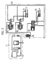
- Fig. 2 is an explanatory view for explaining a hydraulic system which constructs the shifting device.
- a hydraulic source 11 supplies fluid pressure to control selection and speed-change of the shift forks 6 to a shift select controlling portion 13.
- the shift select controlling portion 13 is comprised of a main solenoid 16, a solenoid for shift 17 for pushing out the shift forks 6 respectively connected to the main solenoid 16, a solenoid for shift 18 for drawing in the shift fork 6, a solenoid for select 19, and a select actuator 10 connected to the solenoid for select 19.
- the solenoids for shift 17 and 18 operate as a pressure controlling means for changing of the shift actuator 9 to shift the shifting fork.
- These solenoid valves 16 to 19 are PWM-controlled or electric-controlled by a micro-computer.
- the above hydraulic system operates as follows.
- the main solenoid valve 16 supplies the pressure fluid to the solenoids for shift 17 and 18, and the solenoid for select 19.
- the solenoids for shift 17 and 18 operate as a pressure controlling valve to shift the shift actuator 9 in opposite directions, and to control the fluid pressure supplied to a cylinder chamber of the shift actuator 9 by the PWM-control etc. of the above micro-computer.
- the detected output from each of the sensors 51 to 5 4 are inputted for change the applying load to shift the shift fork shaft 7.
- the solenoid for select 19 controls the select actuator 10 to select a shaft and the fork shaft to be shifted corresponding to the shift (speed change shift).
- the speed change shift is determined by the micro-computer based on a driver's intention and a running condition of the vehicle, and the shaft and the fork shaft 7 to be operated by the select actuator 10 are selected, so that one of the solenoids for shift 17 and 18 is operated.
- the shift fork 6 is shifted via the actuator 9 to operate the synchromesh mechanism 4, whereby the speed-changing operation is performed.
- Fig. 3 shows a relation between the number of rotations of the input shaft 1 and a shifting shiuft of the fork shaft 7, and the time, when the shift is changed from a low-speed to a high-speed.
- the number of rotations of the input gear 1 is the number relative to the transmission and coincides with the number of rotations of the clutch.
- An “index point” is a point where the synchronizer ring 4b encounters with the shifting key firstly, which is also a point where the synchronizer ring 4b contacts with the cone portion 3a of the free-rotatable gear 3 firstly to transmit the synchronizing torque thereto.
- a "balk point” is a point where the synchronizing torque is transmitted from the ring 4b to the free-rotatable gear 3-1 during the speed-changing operation.
- the shifting shift of the fork shaft 7 decreases as shown by a line f.
- the decreasing rate of the number of input rotation becomes larger than that of the line b as shown by a line c, and becomes constant as shown by a line d when the free-rotatable gear 3-1 and the sleeve 4a mesh with each other perfectly.
- the shifting shift of the fork shaft 7 is stopped logically as shown by a line g while the number of input rotation decreases(c), and increases again as shown by a line h when the number of input rotation is stopped (i.e. piece push time of the free-rotatable gear 3-1), and then becomes constant as shown by a line i.
- the transmission which adopts the synchromesh mechanism 4 generally operated as mentioned above.
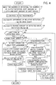
- the speed changing operation is performed with calculating a solenoid fluid pressure to the shift actuator 9, 10 by the micro-coumputer along by a flowchart shown in Fig. 4, during time periods (i) to (iii).
- This program includes (a) take-in of data from the sensors, (b) calculation of the relative rotation on the input shaft and the change amount of input shaft rotation, (c) balk judgement performed by calculating a judge value corresponding to the input rotation based on a predetermined map, (d) correction of synchronizing treating current performed after judgement of the balk point by calculating synchronizing initial current based on the map, and (e)completion of synchronization when the relative rotation is judged to be smaller than the predetermined value.
- a step Sl the number of input rotations, the number of output rotations, shift amount of clutch device, and shift amount of shift device which are detected by the sensors 51 to 54 are inputted.
- a step s2 a low-pass filtering treatment is performed to remove a variable component of the number of rotation.
- the steps s1 and s2 correspond to the above process (a).
- a relative rotation difference on input shaft 1 which is a difference of the number of rotations between the input lshaft and the output shaft 5 and is calculated by subtracting the number of output shaft 5 from the number of input shaft 1 detected by the sensors 51 and 52 is calculated.
- a change rate of detected input rotation detected by the sensor 51 is calculated.
- a step S5 based on an input from the sensor 53, whether the shift fork 6 is positioned at an operating area (i.e. shift change state) or not is judged. If the judgement is NO, which means the shift is positioned in a shift draw-out stage or shift push-apart area, the program returns. To the contrary, if the judgement is YES, which means the shift is positioned in a shift push-in area or synchronize area, whether the balk point judgement has been completed or not is judged at a step s6. If the judgement is NO, whether the shift is within a shift stroke area for balk point judgement or not is judge.
- the "shift stroke area for balk point" means an area where the shifting operation stops temporarily due to abutment of the sleep 4a to the synchronizer ring 4b.
- a change rate of input rotation for judgement d ⁇ inp is calculated at a step s8 by using a map for balk point judgement shown in Fig. 5, to compare it with the change rate of detected input rotation d ⁇ input obtained at the step s4.
- a map for balk point judgement of Fig. 5 a change rate of the smallest rotation of the input shaft 1 which is occurred at the balk point where the synchromesh mechanism 4 frictionally contacts with the free-rotatable gear 3 is dated.
- the number of rotations ⁇ inp of the input shaft 1 and the change rate of input rotation for judgement d ⁇ inp have a relation which can be approximated by a linear equation, and the change rate d ⁇ inp decreases as the number of rotations ⁇ inp increases in the case of up-shift, while it increases in the case of down-shift.
- the balk point is judged when the change rate of detected input rotation d ⁇ inpdt is larger than the change rate of input shaft for judgement d ⁇ inp corresponding to the number of rotations ⁇ inp on this map.
- step s6 When NO is judged in the step s6, it is logically possible to return the program at once, but by providing the steps s7 to s10 which correspond to the above process (c), the program is guarded from the erroneous judgement of balk point.
- step s6 which means the balk point has been already judged
- the program advances to a step 11 to judge the synchronization has been completed or not.
- step s11 the relative rotation difference on input shaft ⁇ ⁇ calculated by the step s3 and a predetermined rotation difference ⁇ ⁇ 1 set in advance are compared to judge the relation of ⁇ 1 for judgement of synchronization completion is satisfied or not. If the judgement is YES,that is completion of synchronization is judged, the program advances to a step 15 for a push-apart where the shift operating area is altered to a shift-apart.
- the program advances to a step 12 to judge whether a synchronizing initial current corresponding to the relative rotation is calculated or not. If NO which means the current has not been calculate is judged, the program advances to a step S13 where the shifting load corresponding to the relative rotation difference based on the synchronizing initial current value shown in Fig. 6 is calculated, and the synchronizing initial current value for driving the shift fork 6 proportional to the shifting load is calculated.
- the program advances to a step S14 where a target rotation valve of the input shaft 1 is set at each of time series points during the necessary time period for synchronization, and the calculation for removing deviation between the number of rotation of the input shaft 1 at each time series point and the target rotation valve is performed by the feedback control.
- the deviation is reduced to the minimum by the controlling operation performed by combining the PID control arbitrarily.
- external disturbance temperature of the operating liquid
- solid difference frequency coefficiency ⁇ of the synchromesh mechanism 4, solenoid quality etc.
- the change rate of input rotation at the rotation drop point, index point and balk point may be larger than that of normal temperature.
- the synchronizing initial current value read from the map by the cycle of computer is corrected over the necessary time period for synchronization. For this reason, the step 14 can be omitted logically, if no external disturbance etc. is existed.
- the steps 12 to S14 correspond to the process (e).
- the controlling of shifting device in which the balk point is judged and the synchronizing initial current is set, in view of the vehicle shock, shifting time and enduring character, can be performed.
- step s8 Another embodiment, that is deformation of the detecting means for rotation change rate will be explained in the following. It is possible, in the step s8, to calculate the change rate of rotation of the input shaft 1 at the balk point, by a difference between the rotation drop rate when the clutch disc D shifts from the connected state to the interrupted state and the rotation change rate of the input shaft 1 changed from the rotation drop rate, or a differenciated value. As can be observed from Fig. 3, the difference of rotation drop rate or the differentiated valve thereof differs from the rotation change rate in value, which makes the detection of balk point possible.
- the driving current can be set with reference to the relation between the shifting load and the necessary time period for synchronization. That is, they are inverse-proportional to each other, so when the shifting load is increased the necessary time period for synchronization is shorted, and when the load is decreased the time period is extended.
- the necessary time period for synchronization can be adjusted by adjusting a pressure value by a linear lolenoid valve which uses a pressure adjusting valve.
- the shifting load corresponding to the predetermined necessary time period for synchronization i.e. synchronizing initial load
Landscapes
- Engineering & Computer Science (AREA)
- General Engineering & Computer Science (AREA)
- Mechanical Engineering (AREA)
- Control Of Transmission Device (AREA)
- Control Of Driving Devices And Active Controlling Of Vehicle (AREA)
Applications Claiming Priority (2)
| Application Number | Priority Date | Filing Date | Title |
|---|---|---|---|
| JP21587998 | 1998-07-30 | ||
| JP21587998A JP3313327B2 (ja) | 1998-07-30 | 1998-07-30 | シンクロメッシュ式トランスミッションのシフト制御装置 |
Publications (3)
| Publication Number | Publication Date |
|---|---|
| EP0976955A2 true EP0976955A2 (de) | 2000-02-02 |
| EP0976955A3 EP0976955A3 (de) | 2001-02-21 |
| EP0976955B1 EP0976955B1 (de) | 2003-12-17 |
Family
ID=16679780
Family Applications (1)
| Application Number | Title | Priority Date | Filing Date |
|---|---|---|---|
| EP99114081A Expired - Lifetime EP0976955B1 (de) | 1998-07-30 | 1999-07-20 | Schaltvorrichtung für ein Synchrongetriebe |
Country Status (4)
| Country | Link |
|---|---|
| US (1) | US6164149A (de) |
| EP (1) | EP0976955B1 (de) |
| JP (1) | JP3313327B2 (de) |
| DE (1) | DE69913614T2 (de) |
Cited By (13)
| Publication number | Priority date | Publication date | Assignee | Title |
|---|---|---|---|---|
| EP1184607A1 (de) * | 2000-08-31 | 2002-03-06 | AISIN AI Co., Ltd. | Steuerungseinrichtung einer Stelleinrichtung für den Einsatz in einer Getriebeeinheit |
| EP1205691A1 (de) * | 2000-11-09 | 2002-05-15 | Isuzu Motors Limited | Getriebeschaltvorrichtung |
| FR2829550A1 (fr) * | 2001-09-12 | 2003-03-14 | Luk Lamellen & Kupplungsbau | Systeme de boite de vitesses automatisee |
| EP1128096A3 (de) * | 2000-02-23 | 2003-05-28 | Isuzu Motors Limited | Getriebe- Hilfsschaltvorrichtung |
| EP1156237A3 (de) * | 2000-05-19 | 2003-06-04 | Isuzu Motors Limited | Getriebe- Hilfsschaltvorrichtung |
| WO2002055903A3 (de) * | 2001-01-12 | 2003-07-03 | Mannesmann Sachs Ag | Kraftfahrzeug mit einem eine mehrfach-kupplungseinrichtung aufweisenden antriebsstrang |
| EP1184605A3 (de) * | 2000-08-31 | 2003-11-19 | AISIN AI Co., Ltd. | Getriebeschaltsteuervorrichtung für Synchrongetriebe |
| FR2859007A1 (fr) * | 2000-10-20 | 2005-02-25 | Luk Lamellen & Kupplungsbau | Vehicule a moteur avec boite de vitesses ainsi que procede pour utiliser un vehicule a moteur |
| GB2406150A (en) * | 2000-10-20 | 2005-03-23 | Luk Lamellen & Kupplungsbau | A method of operating a synchromesh gearbox |
| EP1197685A3 (de) * | 2000-10-13 | 2007-05-02 | AISIN AI Co., Ltd. | Schaltsteuerung für ein Synchrongetriebe |
| EP1983226A1 (de) * | 2007-04-17 | 2008-10-22 | Peugeot Citroën Automobiles S.A. | Verfahren zur Homogenisierung der Veränderungszeit des Übersetzungsverhältnisses eines Getriebes |
| DE10119503B4 (de) * | 2000-04-25 | 2015-11-05 | General Motors Corp. (N.D.Ges.D. Staates Delaware) | Verfahren zum Schalten eines Getriebes eines Hybridfahrzeugs |
| DE102017011429A1 (de) | 2016-12-21 | 2018-06-21 | Scania Cv Ab | Verfahren und System zum Steuern einer Synchronisieranordnung |
Families Citing this family (48)
| Publication number | Priority date | Publication date | Assignee | Title |
|---|---|---|---|---|
| US6481304B1 (en) * | 1999-02-05 | 2002-11-19 | Mitsubishi Jidosha Kogyo Kabushiki Kaisha | Driving-state switching device equipped with synchronizing mechanism |
| JP4447070B2 (ja) * | 1999-05-25 | 2010-04-07 | アイシン・エーアイ株式会社 | 変速機のシフト制御装置 |
| US6251045B1 (en) * | 2000-01-18 | 2001-06-26 | Borgwarner Inc. | Method and apparatus for providing synchronization of low to high shifts in a transfer case |
| JP3499190B2 (ja) * | 2000-04-04 | 2004-02-23 | 株式会社日立製作所 | 自動変速機 |
| JP2001311466A (ja) * | 2000-04-28 | 2001-11-09 | Fuji Heavy Ind Ltd | 変速制御装置 |
| JP2002048225A (ja) * | 2000-08-07 | 2002-02-15 | Aisin Ai Co Ltd | シンクロメッシュ式トランスミッションのための変速装置 |
| JP2002243028A (ja) * | 2001-02-15 | 2002-08-28 | Hitachi Ltd | 自動変速機の制御装置および制御方法 |
| US7146264B2 (en) * | 2001-03-30 | 2006-12-05 | International Business Machines Corporation | Method and system for controlling an automatic transmission using a GPS assist having a learn mode |
| JP4910246B2 (ja) * | 2001-05-21 | 2012-04-04 | アイシン精機株式会社 | 自動変速機の変速制御装置 |
| DE10150720C1 (de) * | 2001-10-13 | 2003-06-12 | Daimler Chrysler Ag | Vorrichtung mit einer Einheit zur Beeinflussung eines Antriebsstrangs, Getriebebaureihe und Verfahren |
| JP4502103B2 (ja) * | 2002-03-27 | 2010-07-14 | スズキ株式会社 | 自動変速機 |
| US6647816B1 (en) | 2002-04-25 | 2003-11-18 | Borgwarner Inc. | Electrically actuated synchronizer for a vehicle transmission |
| JP2003314678A (ja) * | 2002-04-25 | 2003-11-06 | Hitachi Ltd | 自動車の制御方法、および制御装置 |
| DE10231609A1 (de) * | 2002-07-12 | 2004-01-29 | Zf Friedrichshafen Ag | Getriebeschaltung |
| JP2004076841A (ja) * | 2002-08-16 | 2004-03-11 | Suzuki Motor Corp | 車両用自動変速制御装置 |
| US6883394B2 (en) * | 2002-10-15 | 2005-04-26 | Borgwarner, Inc. | Method for controlling the positioning of the synchronizers of a dual clutch transmission |
| US6898992B2 (en) * | 2003-08-08 | 2005-05-31 | Borgwarner, Inc. | Method for controlling the engagement force of the synchronizers of a dual clutch transmission |
| DE10343993B4 (de) * | 2003-09-23 | 2020-04-02 | Zf Friedrichshafen Ag | Schaltgetriebe mit geringer Wellendurchbiegung |
| JP4085946B2 (ja) * | 2003-09-26 | 2008-05-14 | アイシン精機株式会社 | 自動変速機及び自動変速機の油圧制御装置 |
| EP1538370A3 (de) * | 2003-12-05 | 2011-11-30 | Honda Motor Co., Ltd. | Getriebesteuerung |
| JP4500086B2 (ja) * | 2004-04-05 | 2010-07-14 | アイシン・エーアイ株式会社 | 車両用自動変速装置、車両用自動変速装置におけるボーク点検出方法 |
| JP3984237B2 (ja) | 2004-04-20 | 2007-10-03 | 本田技研工業株式会社 | アクチュエータの制御装置 |
| JP2006029441A (ja) * | 2004-07-15 | 2006-02-02 | Nissan Motor Co Ltd | シフトフォークの位置検知装置 |
| CA2583687C (en) * | 2004-10-28 | 2012-10-02 | William Kostuj | Method and device to implement a new golf club specification named waggle weight |
| JP4277820B2 (ja) * | 2005-04-01 | 2009-06-10 | トヨタ自動車株式会社 | 変速機の変速段表示装置 |
| ATE397172T1 (de) * | 2006-03-02 | 2008-06-15 | Elasis Societa Consortile Per | Schalteinrichtung für ein fahrzeuggetriebe |
| JP4762016B2 (ja) * | 2006-03-20 | 2011-08-31 | アイシン・エーアイ株式会社 | 自動変速機の制御方法 |
| JP4902256B2 (ja) * | 2006-04-24 | 2012-03-21 | アイシン・エーアイ株式会社 | 同期噛合式自動変速機 |
| KR101395744B1 (ko) * | 2007-03-02 | 2014-05-16 | 보르그워너 인코퍼레이티드 | 이중 클러치 변속기용 유압 작동식 밸브 장치 |
| CN101946105B (zh) | 2008-03-04 | 2013-07-17 | 博格华纳公司 | 具有区域控制的离合器冷却回路的双离合器变速器 |
| WO2009128806A1 (en) | 2008-04-18 | 2009-10-22 | Borgwarner Inc. | Dual clutch transmission having simplified controls |
| WO2010077560A2 (en) * | 2008-12-09 | 2010-07-08 | Borgwarner Inc. | Automatic transmission for a hybrid vehicle |
| US9086170B2 (en) | 2009-06-29 | 2015-07-21 | Borgwarner Inc. | Hydraulic valve for use in a control module of an automatic transmission |
| JP2011099530A (ja) * | 2009-11-09 | 2011-05-19 | Hino Motors Ltd | 機械式自動変速機の制御装置及び同期開始タイミング取得装置 |
| US8826760B2 (en) | 2009-12-31 | 2014-09-09 | Borgwarner Inc. | Automatic transmission having high pressure actuation and low pressure lube hydraulic circuit |
| US8844393B2 (en) | 2010-04-15 | 2014-09-30 | GM Global Technology Operations LLC | Fork position and synchronization control in a dual clutch transmission using pressure control solenoids |
| US8560192B2 (en) * | 2010-04-15 | 2013-10-15 | GM Global Technology Operations LLC | Control system and method for shift fork position in dual clutch transmissions |
| CN102221085B (zh) * | 2010-04-15 | 2014-10-01 | 通用汽车环球科技运作公司 | 用于双离合变速器中的换档叉位置的控制系统和方法 |
| US8504267B2 (en) * | 2010-04-15 | 2013-08-06 | GM Global Technology Operations LLC | Control system and method for synchronization control in dual clutch transmissions |
| KR101198788B1 (ko) * | 2010-07-16 | 2012-11-07 | 기아자동차주식회사 | 자동화된 수동 변속기용 시프트 모터 제어 장치 및 제어 방법 |
| WO2012066740A1 (ja) * | 2010-11-19 | 2012-05-24 | 株式会社イケヤフォーミュラ | トランスミッション及び変速制御システム |
| KR101305866B1 (ko) * | 2011-06-09 | 2013-09-09 | 현대자동차주식회사 | 차량의 변속기 제어방법 |
| US9551414B2 (en) | 2011-06-10 | 2017-01-24 | Caterpillar Inc. | Synchronizer engagement relative speed-based force profile |
| US9423024B2 (en) * | 2012-01-12 | 2016-08-23 | Ford Global Technologies, Llc | Rapid synchronizer touch point adjustment |
| JP5874651B2 (ja) * | 2013-01-16 | 2016-03-02 | マツダ株式会社 | 手動変速機 |
| KR101629582B1 (ko) | 2014-12-15 | 2016-06-13 | 현대오트론 주식회사 | 변속기 제어 방법 및 장치 |
| JP6550950B2 (ja) * | 2015-06-15 | 2019-07-31 | いすゞ自動車株式会社 | 変速機の制御装置 |
| JP6965792B2 (ja) * | 2018-02-28 | 2021-11-10 | トヨタ自動車株式会社 | 車両用駆動装置 |
Family Cites Families (9)
| Publication number | Priority date | Publication date | Assignee | Title |
|---|---|---|---|---|
| DE2719350A1 (de) * | 1977-04-30 | 1978-11-02 | Bosch Gmbh Robert | Vorrichtung zur ermittlung des schaltrucks in kraftfahrzeugen |
| JPS6212050A (ja) * | 1985-07-10 | 1987-01-21 | Mitsubishi Electric Corp | 蛍光ランプ |
| JPS62266254A (ja) * | 1986-05-10 | 1987-11-19 | Toyota Motor Corp | 車両用自動変速機の油圧制御装置 |
| JPH0625593B2 (ja) * | 1987-09-29 | 1994-04-06 | いすゞ自動車株式会社 | 変速機制御装置 |
| DE4011850B4 (de) * | 1989-04-17 | 2006-04-27 | Luk Lamellen Und Kupplungsbau Beteiligungs Kg | Verfahren zum Steuern einer zwischen einer Antriebsmaschine und einem Getriebe wirksamen automatisierten Reibungskupplung |
| DE19526273C2 (de) * | 1995-07-19 | 1999-12-09 | Ford Werke Ag | Automatisch schaltbares Vorgelege-Wechselgetriebe, insbesondere für Kraftfahrzeuge |
| JPH1122816A (ja) * | 1997-06-30 | 1999-01-26 | Aisin Seiki Co Ltd | シンクロメッシュ式トランスミッションの変速制御装置 |
| US6017291A (en) * | 1998-03-16 | 2000-01-25 | Eaton Corporation | Control system/method for input shaft retarder-assisted upshifts |
| US5989155A (en) * | 1998-04-01 | 1999-11-23 | Eaton Corporation | Engine fuel control for completing shifts in controller-assisted, manually shifted transmission |
-
1998
- 1998-07-30 JP JP21587998A patent/JP3313327B2/ja not_active Expired - Fee Related
-
1999
- 1999-07-20 EP EP99114081A patent/EP0976955B1/de not_active Expired - Lifetime
- 1999-07-20 DE DE69913614T patent/DE69913614T2/de not_active Expired - Lifetime
- 1999-07-23 US US09/359,744 patent/US6164149A/en not_active Expired - Lifetime
Cited By (25)
| Publication number | Priority date | Publication date | Assignee | Title |
|---|---|---|---|---|
| US6637281B2 (en) | 2000-02-23 | 2003-10-28 | Isuzu Motors Limited | Shift-assisting device for a transmission |
| EP1128096A3 (de) * | 2000-02-23 | 2003-05-28 | Isuzu Motors Limited | Getriebe- Hilfsschaltvorrichtung |
| DE10119503B4 (de) * | 2000-04-25 | 2015-11-05 | General Motors Corp. (N.D.Ges.D. Staates Delaware) | Verfahren zum Schalten eines Getriebes eines Hybridfahrzeugs |
| EP1156237A3 (de) * | 2000-05-19 | 2003-06-04 | Isuzu Motors Limited | Getriebe- Hilfsschaltvorrichtung |
| EP1184607A1 (de) * | 2000-08-31 | 2002-03-06 | AISIN AI Co., Ltd. | Steuerungseinrichtung einer Stelleinrichtung für den Einsatz in einer Getriebeeinheit |
| EP1184605A3 (de) * | 2000-08-31 | 2003-11-19 | AISIN AI Co., Ltd. | Getriebeschaltsteuervorrichtung für Synchrongetriebe |
| US6581488B2 (en) | 2000-08-31 | 2003-06-24 | Aisin Ai Co., Ltd. | Control device for an actuator applied in a transmission |
| EP1197685A3 (de) * | 2000-10-13 | 2007-05-02 | AISIN AI Co., Ltd. | Schaltsteuerung für ein Synchrongetriebe |
| FR2859007A1 (fr) * | 2000-10-20 | 2005-02-25 | Luk Lamellen & Kupplungsbau | Vehicule a moteur avec boite de vitesses ainsi que procede pour utiliser un vehicule a moteur |
| GB2406150A (en) * | 2000-10-20 | 2005-03-23 | Luk Lamellen & Kupplungsbau | A method of operating a synchromesh gearbox |
| GB2406150B (en) * | 2000-10-20 | 2005-06-01 | Luk Lamellen & Kupplungsbau | Method for operating a gearbox in a motor vehicle |
| EP1205691A1 (de) * | 2000-11-09 | 2002-05-15 | Isuzu Motors Limited | Getriebeschaltvorrichtung |
| US6658950B2 (en) | 2000-11-09 | 2003-12-09 | Isuzu Motors Limited | Shift control device for a transmission |
| US7287443B2 (en) | 2001-01-12 | 2007-10-30 | Volkswagen Ag | Motor vehicle comprising a drive train having a multiple clutch drive |
| US7107870B2 (en) | 2001-01-12 | 2006-09-19 | Zf Sachs Ag | Motor vehicle comprising a drive train having a multiple clutch drive |
| US7207922B2 (en) | 2001-01-12 | 2007-04-24 | Volkswagen Ag | Motor vehicle comprising a drive train having a multiple clutch drive |
| WO2002055903A3 (de) * | 2001-01-12 | 2003-07-03 | Mannesmann Sachs Ag | Kraftfahrzeug mit einem eine mehrfach-kupplungseinrichtung aufweisenden antriebsstrang |
| WO2003025434A1 (de) * | 2001-09-12 | 2003-03-27 | Luk Lamellen Und Kupplungsbau Beteiligungs Kg | Automatisierte getriebesysteme |
| FR2829550A1 (fr) * | 2001-09-12 | 2003-03-14 | Luk Lamellen & Kupplungsbau | Systeme de boite de vitesses automatisee |
| GB2379721A (en) * | 2001-09-12 | 2003-03-19 | Luk Lamellen & Kupplungsbau | Automated transmission system |
| EP1983226A1 (de) * | 2007-04-17 | 2008-10-22 | Peugeot Citroën Automobiles S.A. | Verfahren zur Homogenisierung der Veränderungszeit des Übersetzungsverhältnisses eines Getriebes |
| FR2915260A1 (fr) * | 2007-04-17 | 2008-10-24 | Peugeot Citroen Automobiles Sa | Procede pour homogeneiser les temps de changement de rapport d'une boite de vitesses. |
| DE102017011429A1 (de) | 2016-12-21 | 2018-06-21 | Scania Cv Ab | Verfahren und System zum Steuern einer Synchronisieranordnung |
| SE541436C2 (en) * | 2016-12-21 | 2019-10-01 | Scania Cv Ab | A method and a system for controlling a synchromesh arrangement |
| DE102017011429B4 (de) * | 2016-12-21 | 2020-03-19 | Scania Cv Ab | Verfahren und System zum Steuern einer Synchronisieranordnung |
Also Published As
| Publication number | Publication date |
|---|---|
| JP3313327B2 (ja) | 2002-08-12 |
| JP2000046176A (ja) | 2000-02-18 |
| EP0976955A3 (de) | 2001-02-21 |
| DE69913614T2 (de) | 2004-09-23 |
| US6164149A (en) | 2000-12-26 |
| DE69913614D1 (de) | 2004-01-29 |
| EP0976955B1 (de) | 2003-12-17 |
Similar Documents
| Publication | Publication Date | Title |
|---|---|---|
| US6164149A (en) | Shifting device for synchromesh-type transmission | |
| US7578766B2 (en) | Apparatus and method for controlling automatic transmission | |
| RU2455180C2 (ru) | Способ контроля работы силовой установки | |
| KR100316749B1 (ko) | 변속제어장치및방법 | |
| US20050037893A1 (en) | Control method for shifting a powershift transmission | |
| US20170001647A1 (en) | Vehicle, control apparatus for vehicle, and control method for vehicle | |
| KR970066214A (ko) | 토크 전달 시스템과 변속기를 제어하는 장치와 방법 | |
| JPH0238748A (ja) | パワートレーンの変速ショック軽減用総合制御装置 | |
| US6254508B1 (en) | Engine torque control during multiple speed changes of an automatic transmission | |
| JPH01208239A (ja) | 車両用自動クラッチの制御装置 | |
| WO2008065922A1 (en) | Shifting time control device for vehicular power transmission system | |
| US6882925B2 (en) | Gear stage detection device | |
| JPH0771492A (ja) | 自動クラッチの制御装置 | |
| JP3486074B2 (ja) | 車両用自動変速機の制御装置 | |
| EP3351416B1 (de) | Drehzahlanzeigevorrichtung | |
| JP2977015B2 (ja) | 車両用油圧作動式変速機の油圧制御装置 | |
| EP1188958B1 (de) | Gerät und Verfahren zur Bestimmung der vollständigen Aufladung des Kolbenhubs für ein automatisches Getriebe | |
| JPH09105454A (ja) | 自動変速機の制御方法および制御装置 | |
| JPH05223166A (ja) | 自動変速機のライン圧制御装置 | |
| US7468017B2 (en) | Gear shifting completion determination device for automatic transmission | |
| JPH08326891A (ja) | 車両用無段変速機の変速制御装置 | |
| JPS61105235A (ja) | エンジン回転速度に基づく制御の開始又は終了方法 | |
| KR100405741B1 (ko) | 자동 변속기의 변속 제어장치 및 방법 | |
| JP2000120853A (ja) | 車両用自動変速機の変速制御装置 | |
| JPS6361649A (ja) | 無段変速機の制御装置 |
Legal Events
| Date | Code | Title | Description |
|---|---|---|---|
| PUAI | Public reference made under article 153(3) epc to a published international application that has entered the european phase |
Free format text: ORIGINAL CODE: 0009012 |
|
| 17P | Request for examination filed |
Effective date: 19990816 |
|
| AK | Designated contracting states |
Kind code of ref document: A2 Designated state(s): DE FR GB |
|
| AX | Request for extension of the european patent |
Free format text: AL;LT;LV;MK;RO;SI |
|
| PUAL | Search report despatched |
Free format text: ORIGINAL CODE: 0009013 |
|
| AK | Designated contracting states |
Kind code of ref document: A3 Designated state(s): AT BE CH CY DE DK ES FI FR GB GR IE IT LI LU MC NL PT SE |
|
| AX | Request for extension of the european patent |
Free format text: AL;LT;LV;MK;RO;SI |
|
| AKX | Designation fees paid |
Free format text: DE FR GB |
|
| 17Q | First examination report despatched |
Effective date: 20020726 |
|
| GRAP | Despatch of communication of intention to grant a patent |
Free format text: ORIGINAL CODE: EPIDOSNIGR1 |
|
| GRAS | Grant fee paid |
Free format text: ORIGINAL CODE: EPIDOSNIGR3 |
|
| GRAA | (expected) grant |
Free format text: ORIGINAL CODE: 0009210 |
|
| AK | Designated contracting states |
Kind code of ref document: B1 Designated state(s): DE FR GB |
|
| REG | Reference to a national code |
Ref country code: GB Ref legal event code: FG4D |
|
| REF | Corresponds to: |
Ref document number: 69913614 Country of ref document: DE Date of ref document: 20040129 Kind code of ref document: P |
|
| ET | Fr: translation filed | ||
| PLBE | No opposition filed within time limit |
Free format text: ORIGINAL CODE: 0009261 |
|
| STAA | Information on the status of an ep patent application or granted ep patent |
Free format text: STATUS: NO OPPOSITION FILED WITHIN TIME LIMIT |
|
| 26N | No opposition filed |
Effective date: 20040920 |
|
| REG | Reference to a national code |
Ref country code: FR Ref legal event code: PLFP Year of fee payment: 17 |
|
| REG | Reference to a national code |
Ref country code: FR Ref legal event code: PLFP Year of fee payment: 18 |
|
| REG | Reference to a national code |
Ref country code: FR Ref legal event code: PLFP Year of fee payment: 19 |
|
| PGFP | Annual fee paid to national office [announced via postgrant information from national office to epo] |
Ref country code: FR Payment date: 20170613 Year of fee payment: 19 |
|
| PGFP | Annual fee paid to national office [announced via postgrant information from national office to epo] |
Ref country code: DE Payment date: 20170711 Year of fee payment: 19 Ref country code: GB Payment date: 20170719 Year of fee payment: 19 |
|
| REG | Reference to a national code |
Ref country code: DE Ref legal event code: R119 Ref document number: 69913614 Country of ref document: DE |
|
| GBPC | Gb: european patent ceased through non-payment of renewal fee |
Effective date: 20180720 |
|
| PG25 | Lapsed in a contracting state [announced via postgrant information from national office to epo] |
Ref country code: FR Free format text: LAPSE BECAUSE OF NON-PAYMENT OF DUE FEES Effective date: 20180731 Ref country code: DE Free format text: LAPSE BECAUSE OF NON-PAYMENT OF DUE FEES Effective date: 20190201 Ref country code: GB Free format text: LAPSE BECAUSE OF NON-PAYMENT OF DUE FEES Effective date: 20180720 |