EP0976975A2 - Kühlvorrichtung für Halogenlampen in Mikrowellenofen - Google Patents
Kühlvorrichtung für Halogenlampen in Mikrowellenofen Download PDFInfo
- Publication number
- EP0976975A2 EP0976975A2 EP99113863A EP99113863A EP0976975A2 EP 0976975 A2 EP0976975 A2 EP 0976975A2 EP 99113863 A EP99113863 A EP 99113863A EP 99113863 A EP99113863 A EP 99113863A EP 0976975 A2 EP0976975 A2 EP 0976975A2
- Authority
- EP
- European Patent Office
- Prior art keywords
- lamp
- light reflection
- light
- cavity
- cooling device
- Prior art date
- Legal status (The legal status is an assumption and is not a legal conclusion. Google has not performed a legal analysis and makes no representation as to the accuracy of the status listed.)
- Granted
Links
- 238000001816 cooling Methods 0.000 title claims abstract description 48
- 229910052736 halogen Inorganic materials 0.000 title abstract description 51
- 150000002367 halogens Chemical class 0.000 title abstract description 51
- 238000007789 sealing Methods 0.000 claims abstract description 44
- 238000010438 heat treatment Methods 0.000 claims abstract description 13
- 239000012212 insulator Substances 0.000 claims description 6
- 239000003989 dielectric material Substances 0.000 claims description 5
- 238000010411 cooking Methods 0.000 description 21
- 235000013305 food Nutrition 0.000 description 16
- 235000013550 pizza Nutrition 0.000 description 4
- 238000010276 construction Methods 0.000 description 2
- 239000012535 impurity Substances 0.000 description 2
- 230000000630 rising effect Effects 0.000 description 2
- 238000007792 addition Methods 0.000 description 1
- 229910010293 ceramic material Inorganic materials 0.000 description 1
- 230000007547 defect Effects 0.000 description 1
- 238000001704 evaporation Methods 0.000 description 1
- 230000008020 evaporation Effects 0.000 description 1
- 235000013611 frozen food Nutrition 0.000 description 1
- WABPQHHGFIMREM-UHFFFAOYSA-N lead(0) Chemical compound [Pb] WABPQHHGFIMREM-UHFFFAOYSA-N 0.000 description 1
- 239000008267 milk Substances 0.000 description 1
- 210000004080 milk Anatomy 0.000 description 1
- 235000013336 milk Nutrition 0.000 description 1
- 230000004048 modification Effects 0.000 description 1
- 238000012986 modification Methods 0.000 description 1
- 230000005855 radiation Effects 0.000 description 1
- 239000000779 smoke Substances 0.000 description 1
- 238000006467 substitution reaction Methods 0.000 description 1
- 238000010257 thawing Methods 0.000 description 1
Images


Classifications
-
- F—MECHANICAL ENGINEERING; LIGHTING; HEATING; WEAPONS; BLASTING
- F24—HEATING; RANGES; VENTILATING
- F24C—DOMESTIC STOVES OR RANGES ; DETAILS OF DOMESTIC STOVES OR RANGES, OF GENERAL APPLICATION
- F24C15/00—Details
- F24C15/10—Tops, e.g. hot plates; Rings
-
- F—MECHANICAL ENGINEERING; LIGHTING; HEATING; WEAPONS; BLASTING
- F21—LIGHTING
- F21V—FUNCTIONAL FEATURES OR DETAILS OF LIGHTING DEVICES OR SYSTEMS THEREOF; STRUCTURAL COMBINATIONS OF LIGHTING DEVICES WITH OTHER ARTICLES, NOT OTHERWISE PROVIDED FOR
- F21V29/00—Protecting lighting devices from thermal damage; Cooling or heating arrangements specially adapted for lighting devices or systems
- F21V29/50—Cooling arrangements
- F21V29/70—Cooling arrangements characterised by passive heat-dissipating elements, e.g. heat-sinks
- F21V29/83—Cooling arrangements characterised by passive heat-dissipating elements, e.g. heat-sinks the elements having apertures, ducts or channels, e.g. heat radiation holes
-
- F—MECHANICAL ENGINEERING; LIGHTING; HEATING; WEAPONS; BLASTING
- F21—LIGHTING
- F21V—FUNCTIONAL FEATURES OR DETAILS OF LIGHTING DEVICES OR SYSTEMS THEREOF; STRUCTURAL COMBINATIONS OF LIGHTING DEVICES WITH OTHER ARTICLES, NOT OTHERWISE PROVIDED FOR
- F21V19/00—Fastening of light sources or lamp holders
- F21V19/0075—Fastening of light sources or lamp holders of tubular light sources, e.g. ring-shaped fluorescent light sources
-
- F—MECHANICAL ENGINEERING; LIGHTING; HEATING; WEAPONS; BLASTING
- F21—LIGHTING
- F21V—FUNCTIONAL FEATURES OR DETAILS OF LIGHTING DEVICES OR SYSTEMS THEREOF; STRUCTURAL COMBINATIONS OF LIGHTING DEVICES WITH OTHER ARTICLES, NOT OTHERWISE PROVIDED FOR
- F21V29/00—Protecting lighting devices from thermal damage; Cooling or heating arrangements specially adapted for lighting devices or systems
- F21V29/50—Cooling arrangements
- F21V29/60—Cooling arrangements characterised by the use of a forced flow of gas, e.g. air
- F21V29/67—Cooling arrangements characterised by the use of a forced flow of gas, e.g. air characterised by the arrangement of fans
- F21V29/673—Cooling arrangements characterised by the use of a forced flow of gas, e.g. air characterised by the arrangement of fans the fans being used for intake
-
- H—ELECTRICITY
- H05—ELECTRIC TECHNIQUES NOT OTHERWISE PROVIDED FOR
- H05B—ELECTRIC HEATING; ELECTRIC LIGHT SOURCES NOT OTHERWISE PROVIDED FOR; CIRCUIT ARRANGEMENTS FOR ELECTRIC LIGHT SOURCES, IN GENERAL
- H05B6/00—Heating by electric, magnetic or electromagnetic fields
- H05B6/64—Heating using microwaves
- H05B6/6444—Aspects relating to lighting devices in the microwave cavity
-
- F—MECHANICAL ENGINEERING; LIGHTING; HEATING; WEAPONS; BLASTING
- F21—LIGHTING
- F21W—INDEXING SCHEME ASSOCIATED WITH SUBCLASSES F21K, F21L, F21S and F21V, RELATING TO USES OR APPLICATIONS OF LIGHTING DEVICES OR SYSTEMS
- F21W2131/00—Use or application of lighting devices or systems not provided for in codes F21W2102/00-F21W2121/00
- F21W2131/30—Lighting for domestic or personal use
- F21W2131/307—Lighting for domestic or personal use for ovens
Definitions
- the present invention relates, in general, to a cooling device for halogen lamps in microwave ovens and, more particularly, to a cooling device designed to expose the sealing parts of a halogen lamp to a cooling air current.
- cooking devices As well known to those skilled in the art, a variety of cooking devices have been proposed and used.
- the primary one is cooking ware, which is designed to have a shape suitable for containing food therein and is laid on a heater so as to be directly heated by the heater while cooking.
- microwave ovens using a magnetron as a heat source.
- the magnetron is electrically operated to generate microwaves and applies the microwaves to food in a cavity, thus allowing the microwaves to cause an active molecular motion in the food.
- Such an active molecular motion in the food generates molecular kinetic energy, thus heating and cooking the food.
- Such microwave ovens are advantageous in that they have a simple construction and are convenient to a user while cooking, and easily and simply heat food in the cavity.
- the microwave ovens are thus somewhat preferably used for some cooking applications, such as a thawing operation for frozen food or a heating operation for milk requiring to be heated to a desired temperature.
- the ovens have a defect in their heating style in addition to limited output power of the magnetron, and so it is almost impossible to freely or preferably use them for a variety of cooking applications, without limitation.
- the conventional microwave ovens only utilize a magnetron as a heat source, thus undesirably having a single heating style.
- the output power of the magnetron, installed in such ovens is limited to a predetermined level. Therefore, the conventional microwave ovens fail to provide a quick and highly effective cooking operation. During a cooking operation utilizing such a microwave oven, food in a cavity is heated at its internal and external portions at the same time, and this may be an advantage of the oven in some cases.
- microwave ovens having another heat source in addition to a magnetron
- a microwave oven having a convection heater in addition to a magnetron in a casing and originally designed to be used for a variety of cooking applications
- a convection heater only acts as a single heat source, thus failing to allow the microwave oven to have a variety of operational functions.
- the conventional microwave ovens are problematic in that they have a single heating style utilizing microwaves, limited output power of a magnetron, and cause the evaporation of an exceeding amount of moisture from food.
- the microwave ovens having another heater in addition to a magnetron, fail to completely overcome the problems experienced in the conventional microwave ovens.
- a lamp wherein at least 90% of the radiation energy has a wavelength of not longer than 1 ⁇ m, is used as the additional heat source.
- both visible rays and infrared rays from the lamp are appropriately used, and it is possible to preferably heat the exterior and interior of food while making the most of characteristics of the food.
- An example of such a lamp is a halogen lamp.
- the heating styles for the exterior and interior of food are different from each other. While cooking pizza utilizing a halogen lamp, it is possible to appropriately heat the pizza in a way such that the exterior of the pizza is heated to become crisp and the interior is heated to be soft while maintaining appropriate moisture.
- Fig. 1 is a conventional microwave oven utilizing a halogen lamp as an additional heat source.
- the microwave oven comprises a halogen lamp 12 installed on the top wall 10 of a cavity 2.
- the microwave oven uses the light waves, radiated from the lamp 12, for heating food in the same manner as that described above, with the characteristics of the light waves remaining the same as that described above.
- a light reflection plate 14 is installed at a position above the halogen lamp 12, thus reflecting any light waves, emanating upwardly from the lamp 12, back downwardly into the cavity 2.
- a plurality of light transmitting holes 16 are formed on the top wall of the cavity 2, with the halogen lamp 12 being held on the top wall.
- the structure for holding the halogen lamp 12 within the reflection plate 14 is shown in Figs. 2 and 3.
- the reflection plate 14, surrounding the halogen lamp 12 is closed by a support member 18 at each end thereof.
- the support member 18 is also used for supporting each end of the lamp 12.
- the halogen lamp 12 has a sealing part 12a at each end thereof. At the sealing part 12a, an external lead wire 17 is connected to an internal filament 12b of the lamp 12.
- An electric insulator part 12c made of a ceramic material, is provided on each end of the lamp 12 at a position outside the sealing part 12a.
- the conventional structure for holding the halogen lamp 12 relative to the light reflection plate 14 is designed as follows.
- the halogen lamp 12 When the halogen lamp 12 is turned on and radiates the heating light, the interior of the reflection plate 14 is further heated to a higher temperature. In this regard, it is a very important factor to effectively cool the sealing parts 12a to a desired temperature. When the sealing parts 12a fail to be effectively cooled, the expected life span of the lamp 12 is undesirably shortened. This results in a reduction in the operational reliability and market competitiveness of the microwave ovens.
- an object of the present invention is to provide a cooling device for halogen lamps in microwave ovens, which is designed to effectively cool the sealing parts of a halogen lamp.
- the present invention provides a cooling device for light radiating lamps in microwave ovens, comprising: a light radiating lamp installed on a top wall of a cavity of a microwave oven, the lamp being operated by electric power applied thereto through a sealing part provided at each end thereof, the lamp thus radiating heating light waves, having a predetermined wavelength, into the cavity; a light reflection means surrounding and holding the light radiating lamp while forming a lamp chamber on the top wall of the cavity and allowing the light waves to be guided from the lamp into the cavity, with the sealing part of the lamp being positioned outside the light reflection means; and cooling means for generating a cooling air current and guiding the cooling air current to the sealing part positioned outside the light reflection means.
- the support means comprises an elastic clamp having a fitting mouth at its top end, thus removably clamping each end of the lamp.
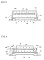
- Fig. 4 is a front sectional view, showing a structure for holding the halogen lamp in a microwave oven in accordance with the primary embodiment of this invention.
- the two sealing parts 30a of the halogen lamp 30 are positioned outside the light reflection plate 32.
- the sealing parts 30a are completely exposed to the cooling air current F, emanating from the cooling fan unit (not shown), thus being effectively cooled by the air current.
- the reference numeral 42 denotes a mesh member which guides the light wave from the halogen lamp 30 into the cavity 2 and intercepts the microwave from the cavity 2, thus protecting the lamp 42.
- the reference numeral 44 denotes a filter protection filter, which protects the halogen lamp 30 from impurities rising from food in the cavity 2 during a cooking operation.
- the halogen lamp 30 is held with each end of the lamp 30 passing through the lamp holding hole 34a formed on each side member 34 of the reflection plate 32. Therefore, the two sealing parts 30a of the lamp 30 are positioned outside the side members 34.
- Fig. 5 is a perspective view, showing a structure for holding the halogen lamp in a microwave oven in accordance with the second embodiment of this invention.
- the halogen lamp 30 is held by the side members 34 of the reflection plate 32 with the sealing parts 30a being positioned outside the side members 34.
- the lamp 30 is held by an elastic clamp 37 at each electric insulator part 30b thereof.
- the above clamp 37 comprises two elastic arms 37a and 37b, which are oppositely positioned to form a fitting mouth at the top end of the clamp 37.
- the clamp 37 is fixed to the top wall of the cavity 2 at its bottom end.
- the bottom of the clamp 37 integrally extends from each side member 34 outwardly.
- the clamp 37 may be separately produced prior to being fixedly mounted to a desired position of the top wall of the cavity 2 without affecting the functioning of this invention.
- the halogen lamp 30 is elastically held on the two clamps 37 by fitting the two insulator parts 30b into the mouth of the clamps 37.
- another part of the lamp 30 in place of the insulator parts 30b may be held on the clamps 37 without affecting the functioning of this invention. That is, the halogen lamp 30 may be held on the clamps 37 at the insulator parts 30b or at the sealing parts 30a without affecting the functioning of this invention if the sealing parts 30a are positioned outside the reflection plate 32.
- the halogen lamp 30 When the halogen lamp 30 is held on the clamps 37 at the sealing parts 30a with the parts 30a being positioned outside the reflection plate 32, it is preferable to position the light radiating body of the lamp 30 within the reflection plate 32.
- the light radiating body of the lamp 30 When the light radiating body of the lamp 30 is exceedingly exposed to the outside of the lamp holding holes 34a of the side members 34, the energy loss of the light waves, emanating from the lamp 30, exceeds an acceptable level. Therefore, it is necessary to position the light radiating body of the lamp 30 within the reflection plate 32.
- each side member 34 of the reflection plate 32 is provided with a lamp holding hole 34a at the center thereof.
- a plurality of air passing holes 36 are formed on each side member 34 at a position around the lamp holding hole 34a, thus allowing the cooling air current to be guided into the interior of the reflection plate 32.
- the halogen lamp 36 is cooled as follows.
- the cooling fan unit (not shown) is turned on and generates a cooling air current F.
- the flowing direction of the current F is shown by the arrows in Figs. 4 and 5.
- the cooling air current F is primarily brought into contact with the sealing parts 30a positioned outside the reflection plate 32, thus cooling the sealing parts 30a.
- the cooling air current F thereafter, flows over the top wall and the sidewall of the reflection plate 32, thus cooling the plate 32.
- the cooling air current F passes through the air passing holes 36 of the side members 34, thus being introduced into the reflection plate 32.
- the cooling air current F cools the surface of the halogen lamp 30 while passing along the lamp 30 prior to being discharged from the plate 32 into the atmosphere.
- the present invention provides a cooling device for a halogen lamp 30 in microwave ovens.
- the sealing parts 30a of the halogen lamp 30 are positioned outside the reflection plate 32. Therefore, the heated sealing parts 30a are effectively and easily cooled to a desired temperature by the cooling air current.
- a plurality of air passing holes are formed on each side member of the reflection plate so as to introduce the cooling air current into the interior of the reflection plate. Therefore, this device effectively cools the external surface of the halogen lamp.
- the cooling device of this invention effectively cools the sealing parts of a halogen lamp in addition to said lamp in a microwave oven. Therefore, the device allows the halogen lamp to normally perform its designed operational function for a lengthy period of time, thereby improving the operational reliability and market competitiveness of the microwave ovens.
Landscapes
- Engineering & Computer Science (AREA)
- General Engineering & Computer Science (AREA)
- Physics & Mathematics (AREA)
- Electromagnetism (AREA)
- Chemical & Material Sciences (AREA)
- Combustion & Propulsion (AREA)
- Mechanical Engineering (AREA)
- Electric Stoves And Ranges (AREA)
- Electric Ovens (AREA)
- Constitution Of High-Frequency Heating (AREA)
- Control Of High-Frequency Heating Circuits (AREA)
- Arrangement Of Elements, Cooling, Sealing, Or The Like Of Lighting Devices (AREA)
Applications Claiming Priority (2)
| Application Number | Priority Date | Filing Date | Title |
|---|---|---|---|
| KR1019980030640A KR100329543B1 (ko) | 1998-07-29 | 1998-07-29 | 전자레인지의할로겐램프냉각구조 |
| KR9830640 | 1998-07-29 |
Publications (3)
| Publication Number | Publication Date |
|---|---|
| EP0976975A2 true EP0976975A2 (de) | 2000-02-02 |
| EP0976975A3 EP0976975A3 (de) | 2002-03-06 |
| EP0976975B1 EP0976975B1 (de) | 2007-09-12 |
Family
ID=19545621
Family Applications (1)
| Application Number | Title | Priority Date | Filing Date |
|---|---|---|---|
| EP99113863A Expired - Lifetime EP0976975B1 (de) | 1998-07-29 | 1999-07-15 | Kühlvorrichtung für Halogenlampen in Mikrowellenofen |
Country Status (6)
| Country | Link |
|---|---|
| US (1) | US6093919A (de) |
| EP (1) | EP0976975B1 (de) |
| JP (1) | JP2000046347A (de) |
| KR (1) | KR100329543B1 (de) |
| CN (1) | CN1138942C (de) |
| DE (1) | DE69937089T2 (de) |
Cited By (1)
| Publication number | Priority date | Publication date | Assignee | Title |
|---|---|---|---|---|
| US6900422B2 (en) | 2000-09-28 | 2005-05-31 | Bsh Bosch Und Siemens Hausgeraete Gmbh | Microwave device |
Families Citing this family (22)
| Publication number | Priority date | Publication date | Assignee | Title |
|---|---|---|---|---|
| DE60132423T2 (de) * | 2000-11-30 | 2009-01-15 | Lg Electronics Inc. | Heizvorrichtung für einen Mikrowellenherd |
| CN100343582C (zh) * | 2002-04-29 | 2007-10-17 | 乐金电子(天津)电器有限公司 | 微波炉的灯设置结构 |
| US6744017B2 (en) * | 2002-05-29 | 2004-06-01 | Ibis Technology Corporation | Wafer heating devices for use in ion implantation systems |
| KR20050056053A (ko) * | 2003-12-09 | 2005-06-14 | 삼성전자주식회사 | 램프 조립체와 이를 구비한 조리장치 |
| KR20050056723A (ko) * | 2003-12-10 | 2005-06-16 | 삼성전자주식회사 | 조리장치 |
| WO2006030370A1 (en) * | 2004-09-16 | 2006-03-23 | Koninklijke Philips Electronics N.V. | Lamp assembly with lamp and reflector. |
| US20080190300A1 (en) * | 2005-05-09 | 2008-08-14 | Adamski Joseph R | Radiant Oven Having Octagonal Cell and/or Sliding Heating Elements |
| KR100747810B1 (ko) * | 2005-12-14 | 2007-08-08 | 엘지전자 주식회사 | 전기 오븐 |
| JP4627745B2 (ja) * | 2006-06-07 | 2011-02-09 | 日立アプライアンス株式会社 | 加熱調理器 |
| US8330083B2 (en) | 2007-11-30 | 2012-12-11 | Hearthware, Inc. | Portable countertop electric oven |
| US7964824B2 (en) * | 2007-11-30 | 2011-06-21 | Ibc-Hearthware, Inc. | System, method and computer program product for programmable counter-top electric oven |
| US8835810B2 (en) * | 2007-11-30 | 2014-09-16 | Nuwave LLC | System and method for a programmable counter-top electric dehydrator |
| JP5197307B2 (ja) * | 2008-11-04 | 2013-05-15 | 三菱電機株式会社 | 加熱調理器 |
| USD693643S1 (en) | 2010-03-12 | 2013-11-19 | Hearthware Inc. | Power head for a portable countertop electric oven |
| CN101979941B (zh) * | 2010-09-30 | 2011-12-14 | 张家港市益成机械有限公司 | 烘箱中插入式灯管的导向结构 |
| CN102012153A (zh) * | 2010-11-15 | 2011-04-13 | 洪正中 | 智能多级变频微波及光波履带调速隧道式型煤烘干设备 |
| FR3008019B1 (fr) * | 2013-07-04 | 2015-07-17 | Sidel Participations | Module de chauffage comportant une lampe et une lentille fixee par une bride sur une partie non emissive de la lampe |
| CN106016201A (zh) * | 2016-07-29 | 2016-10-12 | 深圳和而泰智能控制股份有限公司 | Led灯具、烤箱及微波炉 |
| KR102521492B1 (ko) | 2016-09-08 | 2023-04-14 | 삼성전자주식회사 | 오븐 |
| US11045047B2 (en) | 2017-11-10 | 2021-06-29 | Ron's Enterprises, Inc. | Variable capacity oven |
| JP7108820B2 (ja) * | 2018-04-27 | 2022-07-29 | パナソニックIpマネジメント株式会社 | 加熱調理器 |
| JP7351577B1 (ja) * | 2023-04-10 | 2023-09-27 | 株式会社イーボックス | 流体加温モジュールおよび流体加温システム |
Family Cites Families (7)
| Publication number | Priority date | Publication date | Assignee | Title |
|---|---|---|---|---|
| JPS5421638A (en) * | 1977-07-19 | 1979-02-19 | Matsushita Electric Ind Co Ltd | High frequency heater |
| AU7226681A (en) * | 1980-06-04 | 1981-12-21 | Matsushita Electric Industrial Co., Ltd. | Heat cooking oven |
| US4493960A (en) * | 1982-08-12 | 1985-01-15 | Micro-Quartz Technology Corp. | Ceramic blinders for a microwave oven quartz lamp |
| GB2152790B (en) * | 1983-12-02 | 1986-11-05 | Thorn Emi Domestic Appliances | Additional heating in microwave ovens |
| JP2513829B2 (ja) * | 1989-03-17 | 1996-07-03 | 株式会社東芝 | ヒ―タ付高周波加熱調理装置 |
| JPH035628A (ja) * | 1989-05-30 | 1991-01-11 | Toshiba Corp | ヒータ付高周波加熱調理装置 |
| JPH0552352A (ja) * | 1991-08-23 | 1993-03-02 | Sanyo Electric Co Ltd | 電子レンジ |
-
1998
- 1998-07-29 KR KR1019980030640A patent/KR100329543B1/ko not_active Expired - Fee Related
- 1998-11-30 JP JP10339871A patent/JP2000046347A/ja active Pending
-
1999
- 1999-07-15 EP EP99113863A patent/EP0976975B1/de not_active Expired - Lifetime
- 1999-07-15 DE DE69937089T patent/DE69937089T2/de not_active Expired - Fee Related
- 1999-07-29 CN CNB991111869A patent/CN1138942C/zh not_active Expired - Fee Related
- 1999-07-29 US US09/362,896 patent/US6093919A/en not_active Expired - Lifetime
Non-Patent Citations (1)
| Title |
|---|
| None |
Cited By (1)
| Publication number | Priority date | Publication date | Assignee | Title |
|---|---|---|---|---|
| US6900422B2 (en) | 2000-09-28 | 2005-05-31 | Bsh Bosch Und Siemens Hausgeraete Gmbh | Microwave device |
Also Published As
| Publication number | Publication date |
|---|---|
| DE69937089D1 (de) | 2007-10-25 |
| CN1138942C (zh) | 2004-02-18 |
| DE69937089T2 (de) | 2008-06-12 |
| KR20000009951A (ko) | 2000-02-15 |
| CN1243226A (zh) | 2000-02-02 |
| EP0976975B1 (de) | 2007-09-12 |
| EP0976975A3 (de) | 2002-03-06 |
| US6093919A (en) | 2000-07-25 |
| KR100329543B1 (ko) | 2002-08-21 |
| JP2000046347A (ja) | 2000-02-18 |
Similar Documents
| Publication | Publication Date | Title |
|---|---|---|
| US6093919A (en) | Cooling device for halogen lamps in microwave ovens | |
| EP0977468B1 (de) | Kühlvorrichtung für mit Halogenglühlampen versehene Mikrowellenofen | |
| EP1798477B1 (de) | Elektrischer Ofen | |
| KR100301904B1 (ko) | 할로겐램프를구비한전자레인지의냉각장치 | |
| US8513579B2 (en) | Heater assembly for microwave oven and microwave oven having the same | |
| US6172347B1 (en) | Microwave oven with halogen lamps | |
| EP0977467B1 (de) | Kühlvorrichtung für Halogenlampen in Mikrowellenöfen | |
| KR100717449B1 (ko) | 조리기기의 히터 | |
| PT1671517E (pt) | Um dispositivo de radiação | |
| KR20000010886U (ko) | 전자레인지의 할로겐 히터 균일냉각구조 | |
| KR100275886B1 (ko) | 전자레인지용 할로겐램프의 냉각장치 | |
| KR20090074868A (ko) | 오븐 및 오븐의 사용방법 | |
| KR20020041252A (ko) | 후드겸용 전자레인지의 복사히터 냉각구조 | |
| KR100293350B1 (ko) | 전자레인지용 할로겐 램프 및 그 냉각장치 | |
| JPH035629A (ja) | 加熱調理器 | |
| KR20000003794U (ko) | 전자레인지의 할로겐램프 냉각구조. | |
| KR20000008403U (ko) | 전자레인지의 할로겐램프 실링부 냉각구조 | |
| KR20000003796U (ko) | 전자레인지의 할로겐램프 냉각구조 | |
| KR20020012719A (ko) | 전자레인지의 턴테이블모터 냉각구조 | |
| KR20000003792U (ko) | 전자레인지의 히터 냉각구조 | |
| KR20000003786U (ko) | 전자레인지의 히터 냉각구조 |
Legal Events
| Date | Code | Title | Description |
|---|---|---|---|
| PUAI | Public reference made under article 153(3) epc to a published international application that has entered the european phase |
Free format text: ORIGINAL CODE: 0009012 |
|
| 17P | Request for examination filed |
Effective date: 19990812 |
|
| AK | Designated contracting states |
Kind code of ref document: A2 Designated state(s): AT BE CH CY DE DK ES FI FR GB GR IE IT LI LU MC NL PT SE Kind code of ref document: A2 Designated state(s): DE FR GB IT |
|
| AX | Request for extension of the european patent |
Free format text: AL;LT;LV;MK;RO;SI |
|
| PUAL | Search report despatched |
Free format text: ORIGINAL CODE: 0009013 |
|
| AK | Designated contracting states |
Kind code of ref document: A3 Designated state(s): AT BE CH CY DE DK ES FI FR GB GR IE IT LI LU MC NL PT SE |
|
| AX | Request for extension of the european patent |
Free format text: AL;LT;LV;MK;RO;SI |
|
| RIC1 | Information provided on ipc code assigned before grant |
Free format text: 7F 21V 29/00 A, 7H 05B 6/80 B |
|
| AKX | Designation fees paid |
Free format text: DE FR GB IT |
|
| GRAP | Despatch of communication of intention to grant a patent |
Free format text: ORIGINAL CODE: EPIDOSNIGR1 |
|
| GRAS | Grant fee paid |
Free format text: ORIGINAL CODE: EPIDOSNIGR3 |
|
| GRAA | (expected) grant |
Free format text: ORIGINAL CODE: 0009210 |
|
| AK | Designated contracting states |
Kind code of ref document: B1 Designated state(s): DE FR GB IT |
|
| REG | Reference to a national code |
Ref country code: GB Ref legal event code: FG4D |
|
| REF | Corresponds to: |
Ref document number: 69937089 Country of ref document: DE Date of ref document: 20071025 Kind code of ref document: P |
|
| ET | Fr: translation filed | ||
| PLBE | No opposition filed within time limit |
Free format text: ORIGINAL CODE: 0009261 |
|
| STAA | Information on the status of an ep patent application or granted ep patent |
Free format text: STATUS: NO OPPOSITION FILED WITHIN TIME LIMIT |
|
| 26N | No opposition filed |
Effective date: 20080613 |
|
| PGFP | Annual fee paid to national office [announced via postgrant information from national office to epo] |
Ref country code: GB Payment date: 20090715 Year of fee payment: 11 Ref country code: DE Payment date: 20090709 Year of fee payment: 11 |
|
| PGFP | Annual fee paid to national office [announced via postgrant information from national office to epo] |
Ref country code: IT Payment date: 20090717 Year of fee payment: 11 |
|
| PGFP | Annual fee paid to national office [announced via postgrant information from national office to epo] |
Ref country code: FR Payment date: 20100805 Year of fee payment: 12 |
|
| GBPC | Gb: european patent ceased through non-payment of renewal fee |
Effective date: 20100715 |
|
| PG25 | Lapsed in a contracting state [announced via postgrant information from national office to epo] |
Ref country code: DE Free format text: LAPSE BECAUSE OF NON-PAYMENT OF DUE FEES Effective date: 20110201 |
|
| REG | Reference to a national code |
Ref country code: DE Ref legal event code: R119 Ref document number: 69937089 Country of ref document: DE Effective date: 20110201 |
|
| PG25 | Lapsed in a contracting state [announced via postgrant information from national office to epo] |
Ref country code: IT Free format text: LAPSE BECAUSE OF NON-PAYMENT OF DUE FEES Effective date: 20100715 |
|
| PG25 | Lapsed in a contracting state [announced via postgrant information from national office to epo] |
Ref country code: GB Free format text: LAPSE BECAUSE OF NON-PAYMENT OF DUE FEES Effective date: 20100715 |
|
| REG | Reference to a national code |
Ref country code: FR Ref legal event code: ST Effective date: 20120330 |
|
| PG25 | Lapsed in a contracting state [announced via postgrant information from national office to epo] |
Ref country code: FR Free format text: LAPSE BECAUSE OF NON-PAYMENT OF DUE FEES Effective date: 20110801 |