EP0976997A1 - Wellanker für Feuerfestmaterial - Google Patents
Wellanker für Feuerfestmaterial Download PDFInfo
- Publication number
- EP0976997A1 EP0976997A1 EP99114385A EP99114385A EP0976997A1 EP 0976997 A1 EP0976997 A1 EP 0976997A1 EP 99114385 A EP99114385 A EP 99114385A EP 99114385 A EP99114385 A EP 99114385A EP 0976997 A1 EP0976997 A1 EP 0976997A1
- Authority
- EP
- European Patent Office
- Prior art keywords
- foot
- corrugated
- sections
- arms
- width
- Prior art date
- Legal status (The legal status is an assumption and is not a legal conclusion. Google has not performed a legal analysis and makes no representation as to the accuracy of the status listed.)
- Granted
Links
- 238000004873 anchoring Methods 0.000 title description 2
- 230000009970 fire resistant effect Effects 0.000 title 1
- 229910000831 Steel Inorganic materials 0.000 claims abstract description 9
- 239000010959 steel Substances 0.000 claims abstract description 9
- 239000011819 refractory material Substances 0.000 claims description 5
- 239000000919 ceramic Substances 0.000 description 6
- 238000003466 welding Methods 0.000 description 5
- 238000005452 bending Methods 0.000 description 1
- 230000001419 dependent effect Effects 0.000 description 1
- 210000002414 leg Anatomy 0.000 description 1
- 239000011241 protective layer Substances 0.000 description 1
- 210000000689 upper leg Anatomy 0.000 description 1
Images

Classifications
-
- F—MECHANICAL ENGINEERING; LIGHTING; HEATING; WEAPONS; BLASTING
- F27—FURNACES; KILNS; OVENS; RETORTS
- F27D—DETAILS OR ACCESSORIES OF FURNACES, KILNS, OVENS OR RETORTS, IN SO FAR AS THEY ARE OF KINDS OCCURRING IN MORE THAN ONE KIND OF FURNACE
- F27D1/00—Casings; Linings; Walls; Roofs
- F27D1/14—Supports for linings
- F27D1/141—Anchors therefor
Definitions
- the invention relates to a corrugated anchor for refractory material according to the Preamble of claim 1.
- Corrugated anchors made from a round steel bar that is essentially V-shaped and has a foot made of parallel sections, while the thighs extending outward from the foot are waved in Power plants used for anchoring refractory material and under Use a ceramic ring on appropriate, heat-treated surfaces of heat exchangers or the like. welded out with a protective layer Refractory materials are to be provided.
- the object of the invention is to provide a way of pinning pipes or fins of heat exchangers located between pipes to create wavy anchors for refractory material.
- the foot can be inserted into a ceramic ring, which with the Outside wall of a pipe when placed on it a sufficiently small gap forms, so that a problem-free welding of the corrugated anchor to the pipe anywhere.
- it can be used for such a foot Place the required ceramic ring on a fin between two pipes, see above that the corrugated anchor can also be welded on there without problems.
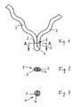
- the corrugated anchor shown in Fig. 1 consists of a round steel piece, the in particular has a diameter of 6 mm.
- the round steel piece is in bent substantially V-shaped and has a foot 1 from parallel to each other extending sections 2 and two from the foot 1 V-shaped outwards extending legs 3 which are corrugated, in particular not only in one Level, but three-dimensional.
- the foot 1 is at least on a sufficiently large part of it Length beginning at the foot end in width less than twice Diameter of the round steel piece formed by the parallel to each other trending sections 2 of the foot 1 to a reduced width with a plan Contact surface 4 of the sections 2 are cold formed together.
- the foot 1 has an essentially oval shape with an average for example from 12 mm to, for example, 9.5 mm reduced width, while the foot 1 according to FIG. 3 even further to a substantially circular Cross-section of a diameter of, for example, 7.8 mm is deformed.
- the foot 1 thus reduced in width can be of the corrugated anchor in a ceramic ring 5 of a correspondingly small diameter use for welding with a tube 6, only a correspondingly small one Gap between the outer wall of the tube 6 and the facing side of the Ceramic ring 5 remains, which ensures problem-free welding.
- the foot 1 thus reduced in width can be the corrugated anchor also in a ceramic ring 5 of a correspondingly small Insert diameter that can be placed on a fin 7 between two tubes 6 is so that the corrugated anchor can be easily welded to the fin 7.
Landscapes
- Engineering & Computer Science (AREA)
- Mechanical Engineering (AREA)
- General Engineering & Computer Science (AREA)
- Furnace Housings, Linings, Walls, And Ceilings (AREA)
- Ceramic Products (AREA)
- Curing Cements, Concrete, And Artificial Stone (AREA)
- Joining Of Building Structures In Genera (AREA)
Abstract
Description
Claims (4)
- Wellanker für Feuerfestmaterial aus einem Rundstahl, der im wesentlichen V-förmig gebogen ist und einen Fuß (1) aus parallel zueinander verlaufenden Abschnitten (2) aufweist, während die sich vom Fuß (1) auswärts erstreckenden Schenkel (3) gewellt sind, dadurch gekennzeichnet, daß die parallel zueinander verlaufenden Abschnitte (2) des Fußes (1) zu einer verringerten Breite mit einer planen Anlagefläche (4) der Abschnitte (2) aneinander kaltverformt sind.
- Wellanker nach Anspruch 1, dadurch gekennzeichnet, daß die Abschnitte (2) des Fußes (1) zu einem im wesentlichen kreisförmigen Querschnitt kaltverformt sind.
- Wellanker nach Anspruch 1 oder 2, dadurch gekennzeichnet, daß der Rundstahl einen Durchmesser von etwa 6 mm und der Fuß (1) eine Breite von höchstens etwa 9,5 mm aufweist.
- Wellanker nach Anspruch 3, dadurch gekennzeichnet, daß der Fuß (1) eine Breite von etwa 7,8 mm aufweist.
Applications Claiming Priority (2)
| Application Number | Priority Date | Filing Date | Title |
|---|---|---|---|
| DE29813329U | 1998-07-27 | ||
| DE29813329U DE29813329U1 (de) | 1998-07-27 | 1998-07-27 | Wellanker für Feuerfestmaterial |
Publications (2)
| Publication Number | Publication Date |
|---|---|
| EP0976997A1 true EP0976997A1 (de) | 2000-02-02 |
| EP0976997B1 EP0976997B1 (de) | 2002-02-27 |
Family
ID=8060420
Family Applications (1)
| Application Number | Title | Priority Date | Filing Date |
|---|---|---|---|
| EP99114385A Expired - Lifetime EP0976997B1 (de) | 1998-07-27 | 1999-07-22 | Wellanker für Feuerfestmaterial |
Country Status (3)
| Country | Link |
|---|---|
| EP (1) | EP0976997B1 (de) |
| AT (1) | ATE213823T1 (de) |
| DE (2) | DE29813329U1 (de) |
Families Citing this family (2)
| Publication number | Priority date | Publication date | Assignee | Title |
|---|---|---|---|---|
| DE102005026530A1 (de) * | 2005-06-08 | 2006-12-14 | Lars Bolte | Metallisches Verankerungselement, insbesondere für feuerfeste Auskleidungen |
| CA3195370A1 (en) | 2014-08-13 | 2016-02-13 | Silicon Holding B.V. | An anchoring assembly for anchoring a liner of a cured lining material |
Citations (5)
| Publication number | Priority date | Publication date | Assignee | Title |
|---|---|---|---|---|
| US3657851A (en) * | 1970-06-24 | 1972-04-25 | Trw Inc | Two-piece refractory anchor for heavy duty construction |
| DE3209607C1 (de) * | 1982-03-17 | 1983-07-21 | Karrena GmbH, 4000 Düsseldorf | Vorrichtung zur Verankerung einer feuerfesten Auskleidung |
| DE3222755A1 (de) * | 1982-06-18 | 1983-12-22 | Didier-Werke Ag, 6200 Wiesbaden | Verankerungsvorrichtung fuer eine ofenauskleidung |
| US4592688A (en) * | 1983-08-12 | 1986-06-03 | Erico Products, Inc. | Insulation hanger and method |
| EP0304705A1 (de) * | 1987-08-29 | 1989-03-01 | JÜNGER & GRÄTER GMBH & CO. Feuerfestbau | Verankerung von vorgehängten Steinplatten für Stahlrohraggregate |
-
1998
- 1998-07-27 DE DE29813329U patent/DE29813329U1/de not_active Expired - Lifetime
-
1999
- 1999-07-22 EP EP99114385A patent/EP0976997B1/de not_active Expired - Lifetime
- 1999-07-22 DE DE59900897T patent/DE59900897D1/de not_active Expired - Lifetime
- 1999-07-22 AT AT99114385T patent/ATE213823T1/de not_active IP Right Cessation
Patent Citations (5)
| Publication number | Priority date | Publication date | Assignee | Title |
|---|---|---|---|---|
| US3657851A (en) * | 1970-06-24 | 1972-04-25 | Trw Inc | Two-piece refractory anchor for heavy duty construction |
| DE3209607C1 (de) * | 1982-03-17 | 1983-07-21 | Karrena GmbH, 4000 Düsseldorf | Vorrichtung zur Verankerung einer feuerfesten Auskleidung |
| DE3222755A1 (de) * | 1982-06-18 | 1983-12-22 | Didier-Werke Ag, 6200 Wiesbaden | Verankerungsvorrichtung fuer eine ofenauskleidung |
| US4592688A (en) * | 1983-08-12 | 1986-06-03 | Erico Products, Inc. | Insulation hanger and method |
| EP0304705A1 (de) * | 1987-08-29 | 1989-03-01 | JÜNGER & GRÄTER GMBH & CO. Feuerfestbau | Verankerung von vorgehängten Steinplatten für Stahlrohraggregate |
Also Published As
| Publication number | Publication date |
|---|---|
| EP0976997B1 (de) | 2002-02-27 |
| ATE213823T1 (de) | 2002-03-15 |
| DE29813329U1 (de) | 1998-12-24 |
| DE59900897D1 (de) | 2002-04-04 |
Similar Documents
| Publication | Publication Date | Title |
|---|---|---|
| CH623128A5 (de) | ||
| DE3303022A1 (de) | Zweikreis-waermeaustauscher | |
| CH670293A5 (de) | ||
| CH638418A5 (de) | Verfahren zum herstellen eines saegedrahtpaketes. | |
| EP0514684A1 (de) | Montageplatte für Schlauchleitungen. | |
| DE2657666A1 (de) | Waermetauschereinsatz | |
| DE102019101330A1 (de) | Tragstruktur für eine Windkraftanlage | |
| DE2308480A1 (de) | Waermetauscher | |
| DE3119628C2 (de) | Flachrohr-Wärmetauscher | |
| EP0225533B1 (de) | Flächenwärmetauscher | |
| EP0976997B1 (de) | Wellanker für Feuerfestmaterial | |
| CH661584A5 (de) | Waermeaustauscher und verfahren zur herstellung derselben. | |
| DE3040802C2 (de) | Wärmetauscher | |
| DE3007902C2 (de) | Verbundprofil | |
| DE3246420C2 (de) | Drahthaspel-Verlegearm | |
| DE3209607C1 (de) | Vorrichtung zur Verankerung einer feuerfesten Auskleidung | |
| DE2853234A1 (de) | Heizrohr | |
| DE1928260A1 (de) | Verfahren zur Herstellung von OEffnungen in Rohrwaenden | |
| DE2161130C2 (de) | Konvektor und Verfahren zu dessen Herstellung | |
| DE3302855C2 (de) | Innenrippenrohr für druckgas- oder druckölbeheizte Heizkessel | |
| DE3701362C2 (de) | ||
| DE69420584T2 (de) | Stahlprofil für sicherheitszaun | |
| EP0389806A1 (de) | Arbeitstisch mit einer metallischen Schneidgutunterlage für eine automatische Schneidanlage | |
| DE3302856C2 (de) | Innenrippenrohr für druckgas- oder druckölbeheizte Heizkessel | |
| DE3319384C2 (de) | Wenigstens zwei parallele, flexible Kunststoffrohre aufweisende, der Förderung von fließfähigen Medien dienende Rohrleitung, insbesondere für die Wärmetechnik |
Legal Events
| Date | Code | Title | Description |
|---|---|---|---|
| PUAI | Public reference made under article 153(3) epc to a published international application that has entered the european phase |
Free format text: ORIGINAL CODE: 0009012 |
|
| AK | Designated contracting states |
Kind code of ref document: A1 Designated state(s): AT BE CH CY DE DK ES FI FR GB GR IE IT LI LU MC NL PT SE |
|
| AX | Request for extension of the european patent |
Free format text: AL;LT;LV;MK;RO;SI |
|
| 17P | Request for examination filed |
Effective date: 20000705 |
|
| AKX | Designation fees paid |
Free format text: AT BE CH CY DE DK ES FI FR GB GR IE IT LI LU MC NL PT SE |
|
| GRAG | Despatch of communication of intention to grant |
Free format text: ORIGINAL CODE: EPIDOS AGRA |
|
| GRAG | Despatch of communication of intention to grant |
Free format text: ORIGINAL CODE: EPIDOS AGRA |
|
| GRAG | Despatch of communication of intention to grant |
Free format text: ORIGINAL CODE: EPIDOS AGRA |
|
| GRAG | Despatch of communication of intention to grant |
Free format text: ORIGINAL CODE: EPIDOS AGRA |
|
| GRAH | Despatch of communication of intention to grant a patent |
Free format text: ORIGINAL CODE: EPIDOS IGRA |
|
| 17Q | First examination report despatched |
Effective date: 20010803 |
|
| RAP1 | Party data changed (applicant data changed or rights of an application transferred) |
Owner name: KOESTER & CO. KRAFTWERK-SERVICE GMBH |
|
| GRAH | Despatch of communication of intention to grant a patent |
Free format text: ORIGINAL CODE: EPIDOS IGRA |
|
| REG | Reference to a national code |
Ref country code: GB Ref legal event code: IF02 |
|
| GRAA | (expected) grant |
Free format text: ORIGINAL CODE: 0009210 |
|
| AK | Designated contracting states |
Kind code of ref document: B1 Designated state(s): AT BE CH CY DE DK ES FI FR GB GR IE IT LI LU MC NL PT SE |
|
| PG25 | Lapsed in a contracting state [announced via postgrant information from national office to epo] |
Ref country code: IE Free format text: LAPSE BECAUSE OF FAILURE TO SUBMIT A TRANSLATION OF THE DESCRIPTION OR TO PAY THE FEE WITHIN THE PRESCRIBED TIME-LIMIT Effective date: 20020227 Ref country code: GR Free format text: LAPSE BECAUSE OF FAILURE TO SUBMIT A TRANSLATION OF THE DESCRIPTION OR TO PAY THE FEE WITHIN THE PRESCRIBED TIME-LIMIT Effective date: 20020227 Ref country code: FI Free format text: LAPSE BECAUSE OF FAILURE TO SUBMIT A TRANSLATION OF THE DESCRIPTION OR TO PAY THE FEE WITHIN THE PRESCRIBED TIME-LIMIT Effective date: 20020227 |
|
| REF | Corresponds to: |
Ref document number: 213823 Country of ref document: AT Date of ref document: 20020315 Kind code of ref document: T |
|
| REG | Reference to a national code |
Ref country code: CH Ref legal event code: EP |
|
| REF | Corresponds to: |
Ref document number: 59900897 Country of ref document: DE Date of ref document: 20020404 |
|
| PG25 | Lapsed in a contracting state [announced via postgrant information from national office to epo] |
Ref country code: SE Free format text: LAPSE BECAUSE OF FAILURE TO SUBMIT A TRANSLATION OF THE DESCRIPTION OR TO PAY THE FEE WITHIN THE PRESCRIBED TIME-LIMIT Effective date: 20020527 Ref country code: PT Free format text: LAPSE BECAUSE OF FAILURE TO SUBMIT A TRANSLATION OF THE DESCRIPTION OR TO PAY THE FEE WITHIN THE PRESCRIBED TIME-LIMIT Effective date: 20020527 Ref country code: DK Free format text: LAPSE BECAUSE OF FAILURE TO SUBMIT A TRANSLATION OF THE DESCRIPTION OR TO PAY THE FEE WITHIN THE PRESCRIBED TIME-LIMIT Effective date: 20020527 |
|
| ET | Fr: translation filed | ||
| GBT | Gb: translation of ep patent filed (gb section 77(6)(a)/1977) |
Effective date: 20020527 |
|
| PG25 | Lapsed in a contracting state [announced via postgrant information from national office to epo] |
Ref country code: AT Free format text: LAPSE BECAUSE OF NON-PAYMENT OF DUE FEES Effective date: 20020722 |
|
| PG25 | Lapsed in a contracting state [announced via postgrant information from national office to epo] |
Ref country code: CY Free format text: LAPSE BECAUSE OF FAILURE TO SUBMIT A TRANSLATION OF THE DESCRIPTION OR TO PAY THE FEE WITHIN THE PRESCRIBED TIME-LIMIT Effective date: 20020731 |
|
| PG25 | Lapsed in a contracting state [announced via postgrant information from national office to epo] |
Ref country code: ES Free format text: LAPSE BECAUSE OF FAILURE TO SUBMIT A TRANSLATION OF THE DESCRIPTION OR TO PAY THE FEE WITHIN THE PRESCRIBED TIME-LIMIT Effective date: 20020829 |
|
| REG | Reference to a national code |
Ref country code: IE Ref legal event code: FD4D |
|
| PLBE | No opposition filed within time limit |
Free format text: ORIGINAL CODE: 0009261 |
|
| STAA | Information on the status of an ep patent application or granted ep patent |
Free format text: STATUS: NO OPPOSITION FILED WITHIN TIME LIMIT |
|
| PG25 | Lapsed in a contracting state [announced via postgrant information from national office to epo] |
Ref country code: MC Free format text: LAPSE BECAUSE OF NON-PAYMENT OF DUE FEES Effective date: 20030201 |
|
| 26N | No opposition filed |
Effective date: 20021128 |
|
| PG25 | Lapsed in a contracting state [announced via postgrant information from national office to epo] |
Ref country code: LI Free format text: LAPSE BECAUSE OF NON-PAYMENT OF DUE FEES Effective date: 20030731 Ref country code: CH Free format text: LAPSE BECAUSE OF NON-PAYMENT OF DUE FEES Effective date: 20030731 |
|
| REG | Reference to a national code |
Ref country code: CH Ref legal event code: PL |
|
| REG | Reference to a national code |
Ref country code: FR Ref legal event code: PLFP Year of fee payment: 18 |
|
| REG | Reference to a national code |
Ref country code: FR Ref legal event code: PLFP Year of fee payment: 19 |
|
| REG | Reference to a national code |
Ref country code: FR Ref legal event code: PLFP Year of fee payment: 20 |
|
| PGFP | Annual fee paid to national office [announced via postgrant information from national office to epo] |
Ref country code: LU Payment date: 20180718 Year of fee payment: 20 |
|
| PGFP | Annual fee paid to national office [announced via postgrant information from national office to epo] |
Ref country code: FR Payment date: 20180725 Year of fee payment: 20 Ref country code: IT Payment date: 20180724 Year of fee payment: 20 Ref country code: NL Payment date: 20180719 Year of fee payment: 20 |
|
| PGFP | Annual fee paid to national office [announced via postgrant information from national office to epo] |
Ref country code: GB Payment date: 20180719 Year of fee payment: 20 Ref country code: BE Payment date: 20180718 Year of fee payment: 20 |
|
| PGFP | Annual fee paid to national office [announced via postgrant information from national office to epo] |
Ref country code: DE Payment date: 20180928 Year of fee payment: 20 |
|
| REG | Reference to a national code |
Ref country code: DE Ref legal event code: R071 Ref document number: 59900897 Country of ref document: DE |
|
| REG | Reference to a national code |
Ref country code: NL Ref legal event code: MK Effective date: 20190721 |
|
| REG | Reference to a national code |
Ref country code: GB Ref legal event code: PE20 Expiry date: 20190721 |
|
| REG | Reference to a national code |
Ref country code: BE Ref legal event code: MK Effective date: 20190722 |
|
| PG25 | Lapsed in a contracting state [announced via postgrant information from national office to epo] |
Ref country code: GB Free format text: LAPSE BECAUSE OF EXPIRATION OF PROTECTION Effective date: 20190721 |