EP0977150A2 - Röntgentomographie- und Bilddiagnostikgerät - Google Patents
Röntgentomographie- und Bilddiagnostikgerät Download PDFInfo
- Publication number
- EP0977150A2 EP0977150A2 EP99305569A EP99305569A EP0977150A2 EP 0977150 A2 EP0977150 A2 EP 0977150A2 EP 99305569 A EP99305569 A EP 99305569A EP 99305569 A EP99305569 A EP 99305569A EP 0977150 A2 EP0977150 A2 EP 0977150A2
- Authority
- EP
- European Patent Office
- Prior art keywords
- pixels
- image
- interest
- pixel
- fat
- Prior art date
- Legal status (The legal status is an assumption and is not a legal conclusion. Google has not performed a legal analysis and makes no representation as to the accuracy of the status listed.)
- Withdrawn
Links
Images


Classifications
-
- A—HUMAN NECESSITIES
- A61—MEDICAL OR VETERINARY SCIENCE; HYGIENE
- A61B—DIAGNOSIS; SURGERY; IDENTIFICATION
- A61B6/00—Apparatus or devices for radiation diagnosis; Apparatus or devices for radiation diagnosis combined with radiation therapy equipment
-
- G—PHYSICS
- G06—COMPUTING OR CALCULATING; COUNTING
- G06T—IMAGE DATA PROCESSING OR GENERATION, IN GENERAL
- G06T7/00—Image analysis
- G06T7/0002—Inspection of images, e.g. flaw detection
- G06T7/0012—Biomedical image inspection
-
- A—HUMAN NECESSITIES
- A61—MEDICAL OR VETERINARY SCIENCE; HYGIENE
- A61B—DIAGNOSIS; SURGERY; IDENTIFICATION
- A61B5/00—Measuring for diagnostic purposes; Identification of persons
- A61B5/48—Other medical applications
- A61B5/4869—Determining body composition
- A61B5/4872—Body fat
-
- A—HUMAN NECESSITIES
- A61—MEDICAL OR VETERINARY SCIENCE; HYGIENE
- A61B—DIAGNOSIS; SURGERY; IDENTIFICATION
- A61B6/00—Apparatus or devices for radiation diagnosis; Apparatus or devices for radiation diagnosis combined with radiation therapy equipment
- A61B6/02—Arrangements for diagnosis sequentially in different planes; Stereoscopic radiation diagnosis
- A61B6/03—Computed tomography [CT]
- A61B6/032—Transmission computed tomography [CT]
-
- A—HUMAN NECESSITIES
- A61—MEDICAL OR VETERINARY SCIENCE; HYGIENE
- A61B—DIAGNOSIS; SURGERY; IDENTIFICATION
- A61B6/00—Apparatus or devices for radiation diagnosis; Apparatus or devices for radiation diagnosis combined with radiation therapy equipment
- A61B6/46—Arrangements for interfacing with the operator or the patient
- A61B6/461—Displaying means of special interest
- A61B6/463—Displaying means of special interest characterised by displaying multiple images or images and diagnostic data on one display
-
- G—PHYSICS
- G06—COMPUTING OR CALCULATING; COUNTING
- G06T—IMAGE DATA PROCESSING OR GENERATION, IN GENERAL
- G06T7/00—Image analysis
- G06T7/10—Segmentation; Edge detection
- G06T7/11—Region-based segmentation
-
- G—PHYSICS
- G06—COMPUTING OR CALCULATING; COUNTING
- G06T—IMAGE DATA PROCESSING OR GENERATION, IN GENERAL
- G06T7/00—Image analysis
- G06T7/10—Segmentation; Edge detection
- G06T7/136—Segmentation; Edge detection involving thresholding
-
- G—PHYSICS
- G06—COMPUTING OR CALCULATING; COUNTING
- G06T—IMAGE DATA PROCESSING OR GENERATION, IN GENERAL
- G06T2207/00—Indexing scheme for image analysis or image enhancement
- G06T2207/10—Image acquisition modality
- G06T2207/10072—Tomographic images
- G06T2207/10081—Computed x-ray tomography [CT]
-
- G—PHYSICS
- G06—COMPUTING OR CALCULATING; COUNTING
- G06T—IMAGE DATA PROCESSING OR GENERATION, IN GENERAL
- G06T2207/00—Indexing scheme for image analysis or image enhancement
- G06T2207/20—Special algorithmic details
- G06T2207/20092—Interactive image processing based on input by user
- G06T2207/20101—Interactive definition of point of interest, landmark or seed
-
- G—PHYSICS
- G06—COMPUTING OR CALCULATING; COUNTING
- G06T—IMAGE DATA PROCESSING OR GENERATION, IN GENERAL
- G06T2207/00—Indexing scheme for image analysis or image enhancement
- G06T2207/30—Subject of image; Context of image processing
- G06T2207/30004—Biomedical image processing
-
- Y—GENERAL TAGGING OF NEW TECHNOLOGICAL DEVELOPMENTS; GENERAL TAGGING OF CROSS-SECTIONAL TECHNOLOGIES SPANNING OVER SEVERAL SECTIONS OF THE IPC; TECHNICAL SUBJECTS COVERED BY FORMER USPC CROSS-REFERENCE ART COLLECTIONS [XRACs] AND DIGESTS
- Y10—TECHNICAL SUBJECTS COVERED BY FORMER USPC
- Y10S—TECHNICAL SUBJECTS COVERED BY FORMER USPC CROSS-REFERENCE ART COLLECTIONS [XRACs] AND DIGESTS
- Y10S378/00—X-ray or gamma ray systems or devices
- Y10S378/901—Computer tomography program or processor
Definitions
- the present invention relates to an X-ray CT (computed tomography) apparatus and an image diagnostic apparatus, and more particularly to an X-ray CT apparatus and an image diagnostic apparatus which enable diagnosis of diverence of the internal organs in a practical level and are useful for diagnosis of diverence of the internal organs.
- X-ray CT computed tomography
- the conventional X-ray CT apparatuses may serve to diagnose diverence of the internal organs.
- X-ray CT computed tomography
- an X-ray CT apparatus for successively acquiring data at different view angles while rotating an X-ray tube (or an X-ray tube and a detector) around a subject, and producing a tomographic image for display by means of a reconstruction operation (or interpolation and reconstruction operations), comprising: threshold range defining means for specifying CT values for a fat portion in the tomographic image to define a threshold range; measurement start point specifying means for specifying one point in a subcutaneous fat region on the image; subcutaneous fat pixel retrieving means for retrieving pixels within a region on the tomographic image that is composed of continuous pixels having CT values within the threshold range and contains the measurement start point, and identifying these pixels as subcutaneous fat pixels; visceral fat pixel retrieving means for retrieving pixels on the tomographic image that have CT values within the threshold range and are not the subcutaneous fat pixels, and identifying these pixels as visceral fat pixels; fat region image display means for displaying at least either of the subcutaneous fat pixels
- the operator is only required to specify minimum and maximum CT values for the fat portion or specify a central CT value and a CT value width for the fat portion, and specify one point in the subcutaneous fat region on the screen. Then the subcutaneous fat pixels and the visceral fat pixels are automatically retrieved, the area ratio thereof is automatically calculated, and the histograms of their pixel values are automatically generated. Next, the fat region image, the area ratio and the histograms are displayed on the same screen. Thus, the diagnosis of diverence of the internal organs is facilitated.
- the X-ray CT apparatus as described regarding the first aspect, comprising: fat pixel extracted image display means for displaying a fat pixel extracted image which enables discrimination between pixels having CT values within the threshold range and other pixels; separation line input means for allowing an operator to input a separation line in the image; region separation means for identifying continuous pixels having CT values within the threshold range and lying across the separation line as discontinuous.
- the subcutaneous fat region and the visceral fat region may be apparently continuous on a tomographic image. In this case, statistical calculations such as those for finding the area ratio of the subcutaneous fat region and the visceral fat region cannot be performed.
- the X-ray CT apparatus of the second aspect even when the subcutaneous fat region and the visceral fat region are apparently continuous, these regions can be separated by the separation line input by the operator.
- the calculations such as those for finding the area ratio of the subcutaneous fat region and the visceral fat region are thus enabled.
- an image diagnostic apparatus for displaying an image and extracting features of a region of interest in the image, comprising: threshold range defining means for specifying pixel values of pixels of interest in the image to define a threshold range; measurement start point specifying means for specifying one point in a local region on the image; local pixel-of-interest retrieving means for retrieving pixels within a region on the image that is composed of continuous pixels having pixel values within the threshold range and contains the measurement start point, and identifying these pixels as local pixels of interest; residual pixel-of-interest retrieving means for retrieving pixels on the image that have pixel values within the threshold range and are not the local pixels of interest, and identifying these pixels as residual pixels of interest; pixel-of-interest region image display means for displaying at least either of the local pixels of interest or the residual pixels of interest in a discriminable mode; area ratio calculating means for calculating the ratio of the area of the local pixels of interest and the area of the residual pixels of interest; histogram generating means
- the operator is only required to specify minimum and maximum pixel values for the pixels of interest or specify a central pixel value and a pixel value width for the pixels of interest, and specify one point in the local region on the screen. Then the local pixels of interest and the residual pixels of interest are automatically retrieved, the area ratio thereof is automatically calculated and the histograms of their pixel values are automatically generated. Next, the pixel-of-interest region image, the area ratio and the histograms are displayed on the same screen. Thus, the features of the pixels of interest can be easily observed. For example, diagnosis of diverence of the internal organs is facilitated.
- the image diagnostic apparatus as described regarding the third aspect, comprising: pixel-of-interest extracted image display means for displaying a pixel-of-interest extracted image which enables discrimination between pixels having pixel values within the threshold range and other pixels; separation line input means for allowing an operator to input a separation line in the image; region separation means for identifying continuous pixels having pixel values within the threshold range and lying across the separation line as discontinuous.
- the local pixel-of-interest region and the residual pixel-of-interest region may be apparently continuous on a tomographic image. In this case, statistical calculations such as those for finding the area ratio of the local pixel-of-interest region and the residual pixel-of-interest region cannot be performed.
- the image diagnostic apparatus of the fourth aspect even when the local pixel-of-interest region and the residual pixel-of-interest region are apparently continuous, these regions can be separated by the separation line input by the operator.
- the calculations such as those for finding the area ratio of the local pixel-of-interest region and the residual pixel-of-interest region are thus enabled.
- the X-ray CT apparatus and the image diagnostic apparatus of the present invention have the following advantages.
- the X-ray CT apparatus of the present invention only by specifying a threshold range to define a fat portion and specifying one point in a subcutaneous fat region, an image which enables discrimination of the fat portion is displayed and the visceral fat ratio and histograms are displayed on the same screen. Therefore, diagnosis and examination of diverence of the internal organs caused by adult-onset diseases can easily be done. Moreover, since the regions can be arbitrarily separated, even when the subcutaneous fat region and the visceral fat region are (apparently) continuous these region can be separated, enabling statistical calculations such as those for finding the area ratio.
- the image diagnostic apparatus of the present invention only by specifying a threshold range to define pixels of interest and specifying one point in a local region, an image which enables discrimination of the pixel-of-interest region is displayed and the area ratio and histograms are displayed on the same screen. Therefore, the features of the pixels of interest can be intuitively recognized. Moreover, since the regions can be arbitrarily separated, even when the local pixel-of-interest region and the residual pixel-of-interest region are (apparently) continuous these region can be separated, enabling statistical calculations such as those for finding the area ratio.
- Figure 1 is a configuration diagram illustrating an X-ray CT apparatus in accordance with a first embodiment of the present invention.
- Figure 2 is a flow chart of fat measurement region specifying processing conducted by the X-ray CT apparatus of Fig. 1.
- Figure 3 is a flow chart of fat measurement image display processing conducted by the X-ray CT apparatus of Fig. 1.
- Figure 4 is an exemplary illustration of a screen for selecting a screen layout.
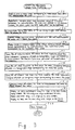
- Figure 5 is a schematic representation of a binary image in which a fat region is extracted and a contour added image in which the contour of the fat region is added to a tomographic image.
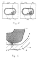
- Figure 6 is an explanatory diagram illustrating input of separation lines and a measurement start point.
- Figure 7 is an exemplary illustration of a screen layout for displaying an axial image of the abdomen in which the fat portion is displayed in a discriminable mode, and histograms on the same screen.
- Figure 8 is a configuration diagram of an image diagnostic apparatus in accordance with a second embodiment of the present invention.
- Figure 9 is a flow chart of measurement region specifying processing conducted by the image diagnostic apparatus of Fig. 8.
- Figure 10 is a flow chart of comparative measurement image display processing conducted by the image diagnostic apparatus of Fig. 8.
- Figure 1 is a configuration diagram of an X-ray CT apparatus in accordance with a first embodiment of the invention.
- the X-ray apparatus 100 comprises an operation console 1, an imaging table 10 and a scan gantry 20.
- the operation console 1 comprises an input device 2 for accepting commands and parameters input by a human operator, a central processing apparatus 3 for conducting scan processing, image reconstruction processing, fat measurement parameter specifying processing, fat measurement image display processing and the like, a control interface 4 for supplying control signals etc. to the imaging table 10 and the scan gantry 20, a data collection buffer 5 for collecting data obtained from the scan gantry 20, a CRT 6 for displaying images etc., and a storage device 7 for storing several data and programs.
- the imaging table 10 moves a subject rested thereon in the direction of the subject's body axis.
- the scan gantry 20 comprises an X-ray tube 21, a collimator 22, a detector 23, a rotation controller 24 for rotating the X-ray tube 21 and the detector 23 etc. around the subject's body axis, an X-ray controller 25 for regulating the timing and strength of X-ray emission, and a data acquisition section 26.
- Figure 2 is a flow chart of fat measurement region specifying processing conducted by the X-ray CT apparatus 100.
- Step P1 a minimum CT value (e.g., -150) and a maximum CT value (e.g., -50) for fat input by the operator are accepted to define a threshold range.
- a central CT value e.g., -100
- a CT value width e.g., 50
- Step P2 screen layout options are displayed on the screen and allows the operator to make a choice. For example, the operator chooses what to display in areas enclosed by broken line among 'Whole' fat, 'Subcutaneous' fat and 'Visceral' fat, as shown in Fig. 4. In this example, the subcutaneous fat is chosen for the left area, and the visceral fat is chosen for the right area.
- Step P3 a binary image is created for display in which the pixel value for pixels having CT values within the threshold range on the tomographic image is one, and the pixel value for other pixels is zero.
- a color image may be displayed instead of the binary image in which the pixels having CT values within the threshold range are displayed in a specific color.
- Figure 5 (a) exemplarily shows the binary image Gb.
- the subcutaneous fat region As and the visceral fat region Av are shown as apparently continuous connected via a bridge portion Ab.
- Step P4 the operator decides whether to conduct region separation. If the region separation is selected, the process goes to Step P5, otherwise to Step P9.
- Step P5 a contour is extracted of the region having a pixel value of one in the binary image Gb, and, as shown in Fig. 5 (b), a contour added image Ga is displayed with the contour superimposed over the tomographic image.
- Step P6 the operator inputs separation lines L1 and L2 on the contour added image Ga, as shown in Fig. 6.
- the process of inputting the separation line is achieved by successively inputting points using, for example, a trackball and a return key to cause the points to sequentially connected by straight lines, and pushing the return key twice at the last point.
- the points may be successively input by clicking a mouse to cause the points to be sequentially connected by straight lines, and double-clicking the mouse at the last point.
- Either one, two or more separation lines may be input as needed.
- the pixel values for the pixels in the original binary image Gb on the separation lines are changed into zero.
- Step P7 the operator decides whether to conduct region deletion.
- the process goes to Step P8, otherwise to Step P9.
- Step P8 the operator specifies a region to be deleted on the contour added image Ga. For example, a region interposed between the separation lines L1 and L2 is specified in Fig. 6. Upon specifying the region, a mark D indicative of deletion is displayed in the specified region. At the same time, the pixel values for the pixels in the original binary image Gb within the specified region is changed into zero.
- Step P9 the operator specifies a measurement start point B in the visceral fat region As on the contour added image Ga, as shown in Fig. 6. Then the fat measurement region specifying process is terminated.
- Figure 3 is a flow chart of fat measurement image display processing by the X-ray CT apparatus 100.
- Step F2 a pixel on the binary image Gb corresponding to the measurement start point B is identified as a subcutaneous fat pixel.
- Step F3 a pixel that has a pixel value of one and is adjacent to the subcutaneous fat pixel is retrieved and appended to the subcutaneous fat pixel; and this step is repeated. When no more pixel to be appended is found, the process goes to Step F4.
- Step F4 pixels having a pixel value of one are retrieved on the binary image Gb and identified as whole fat pixels.
- Step F5 pixels in the binary image Gb that are the whole fat pixels and are not the subcutaneous fat are identified as visceral fat pixels.
- Step F6 the tomographic images are displayed in a display mode which allows discrimination between the pixels corresponding to the subcutaneous fat pixels and the pixels corresponding to the visceral fat pixels, as shown in Fig. 5, according to the aforementioned screen layout selection, in which, in this example, the subcutaneous fat region image and the visceral fat region image have been selected for display. (In Fig. 5, the regions are shown as different patterns of hatching.)
- Step F7 the number of subcutaneous fat pixels is counted and the number is identified as a subcutaneous fat area. Moreover, a histogram of the CT values of the pixels on the tomographic image corresponding to the subcutaneous fat pixels is generated. Furthermore, the perimeter of the subcutaneous fat pixel region is calculated.
- Step F8 the number of whole fat pixels is counted and the number is identified as a whole fat area. Moreover, a histogram of the CT values of the pixels on the tomographic image corresponding to the whole fat pixels is generated.
- Step F9 the number of visceral fat pixels is counted and the number is identified as a visceral fat area. Moreover, a histogram of the CT values of the pixels on the tomographic image corresponding to the visceral fat pixels is generated.
- Step F10 the ratio of the visceral fat area to the subcutaneous fat area is calculated and the ratio is identified as a visceral fat ratio.
- Step F11 the subcutaneous fat region image Gs and the histogram Hs of the CT values of the subcutaneous fat pixels are displayed on the left side, and the visceral fat region image Gv and the histogram Hv of the CT values of the visceral fat pixels are displayed on the right side on the same screen, as shown in Fig. 7, according to the screen layout selection, in which, in this example, the subcutaneous fat and the visceral fat have been selected for the left and right areas, respectively.
- V / S visceral fat area ⁇ subcutaneous fat area ⁇ 100
- S / W subcutaneous fat area ⁇ whole fat area ⁇ 100
- V / W visceral fat area ⁇ whole fat area ⁇ 100
- the subcutaneous fat region perimeter Circ1
- the perimeter of an arbitrarily specified region Circ2
- the respective areas Alignment
- mean CT values Mean
- actual minimum CT values Min
- actual maximum CT values Max
- Sd standard deviations
- Step F12 the screen is saved.
- the operator is only required to define a CT value range of the fat region and specify one point in the subcutaneous fat region, and the images which allow discrimination between subcutaneous fat and visceral fat are displayed and also the visceral fat ratio and histograms are displayed on the same screen.
- the diagnosis of diverence of the internal organs is facilitated when an axial image of the abdomen is employed as the tomographic image Gf.
- the X-ray CT apparatus 100 even when the subcutaneous fat region and the visceral fat region are (apparently) continuous, these regions can be separated by the separation line input by the operator, thereby enabling the area ratio etc. to be calculated.
- Figure 8 is a configuration diagram of an image diagnostic apparatus in accordance with a second embodiment of the present invention.
- the image diagnostic apparatus 700 comprises an imaging apparatus 40 for imaging a subject H such as an X-ray CT apparatus, MRI (magnetic resonance imaging) apparatus and ultrasonic diagnostic apparatus, a processing apparatus 50 for performing measurement parameter specifying processing 51 and comparative measurement image display processing 52 in accordance with the present invention on an image obtained by the imaging apparatus 40, a display monitor 70, and an input device 80.
- an imaging apparatus 40 for imaging a subject H such as an X-ray CT apparatus, MRI (magnetic resonance imaging) apparatus and ultrasonic diagnostic apparatus
- a processing apparatus 50 for performing measurement parameter specifying processing 51 and comparative measurement image display processing 52 in accordance with the present invention on an image obtained by the imaging apparatus 40 a display monitor 70, and an input device 80.
- Figure 9 is a flow chart of the measurement region specifying processing 51 by the image diagnostic apparatus 700.
- Step C1 minimum and maximum pixel values (e.g., CT value or brightness value) of pixels of interest input by a human operator are accepted to define a threshold range.
- minimum and maximum pixel values e.g., CT value or brightness value
- Step C2 a plurality of screen layout patterns are displayed on the screen to allow the operator to make a choice.
- Step C3 an image which allows easy discrimination between pixels having pixel values within the threshold range and other pixels is produced for display.
- Step C4 the operator decides whether to conduct region separation. If the region separation is selected, the process goes to Step C5, otherwise to Step C8.
- Step C5 the operator inputs a separation line on the image. After the separation line has been input, the continuous pixels having pixel values within the threshold range and lying across the separation line are regarded as discontinuous.
- Step C6 the operator decides whether to conduct region deletion. If the region deletion is selected, the process goes to Step C7, otherwise to Step C8.
- Step C7 the operator specifies a region to be deleted on the image.
- the pixel values in the specified region are regarded as having pixel values out of the threshold range.
- Step C8 the operator specifies a measurement start point in a local region on the image. Then the measurement region specifying processing is terminated.
- Figure 10 is a flow chart of the comparative measurement image display processing 52 by the image diagnostic apparatus 700.
- Step H2 a pixel at the measurement start point is identified as a local pixel of interest on the original image.
- Step H3 a pixel that has a pixel value within the threshold range and is adjacent to the local pixel of interest is retrieved on the original image and appended to the local pixel of interest; and this step is repeated.
- Step H4 a pixel that has a pixel value within the threshold range and is adjacent to the local pixel of interest is retrieved on the original image and appended to the local pixel of interest; and this step is repeated.
- Step H4 pixels having pixel values within the threshold range are retrieved on the original image and identified as whole pixels of interest.
- Step H5 pixels that are the whole pixels of interest and are not the local pixels of interest are identified as residual pixels of interest.
- Step H6 if a local pixel-of-interest region image and a residual pixel-of-interest region image are selected for display in the screen layout choice, the local pixels of interest and the residual pixels of interest are given respective discriminable modes.
- Step H7 the number of local pixels of interest is counted and the number is identified as a local pixel-of-interest area. Moreover, a histogram of the pixel values of the local pixels of interest is generated. Furthermore, the perimeter of the local pixel-of-interest region is calculated.
- Step H8 the number of whole pixels of interest is counted and the number is identified as a whole pixel-of-interest area. Moreover, a histogram of the pixel values of the whole pixels of interest is generated.
- Step H9 the number of residual pixels of interest is counted and the number is identified as a residual pixel-of-interest area. Moreover, a histogram of the pixel values of the residual pixels of interest is generated.
- Step H10 the ratio of the residual pixel-of-interest area to the local pixel-of-interest area is calculated and identified as a residual pixel-of-interest ratio.
- Step H11 if the histogram of the pixel values of the local pixels of interest and the histogram of the pixel values of the residual pixels of interest are selected for display in the screen layout choice, the histogram of the pixel values of the local pixels of interest and the histogram of the pixel values of the residual pixels of interest are displayed along with the local pixel-of-interest region image and the residual pixel-of-interest region image on the same screen. Moreover, the residual pixel-of-interest ratio, the perimeter, the local pixel-of-interest area and the residual pixel-of-interest area are displayed on the same screen.
- Step H12 the screen is saved.
- the operator is only required to define a pixel value range of the pixels of interest and specify one point in the local region, and the local pixels of interest and the residual pixels of interest are displayed on an image in a discriminable mode and also the area ratio and histograms are displayed on the same screen.
- the features of the pixels of interest can be easily observed.
- the image diagnostic apparatus 700 even when the local pixel-of-interest region and the residual pixel-of-interest region are (apparently) continuous, these regions can be separated, thereby enabling the area ratio etc. to be calculated.
- an axial image of the abdomen is employed as the original image with fat pixels selected as the pixels of interest and a subcutaneous fat region selected as the local region, then diagnosis of diverence of the internal organs can be performed. Moreover, diagnosis of a lesion site in the liver or in the brain can be performed.
Landscapes
- Engineering & Computer Science (AREA)
- Health & Medical Sciences (AREA)
- Life Sciences & Earth Sciences (AREA)
- Medical Informatics (AREA)
- Physics & Mathematics (AREA)
- General Health & Medical Sciences (AREA)
- Theoretical Computer Science (AREA)
- Surgery (AREA)
- Animal Behavior & Ethology (AREA)
- Veterinary Medicine (AREA)
- Public Health (AREA)
- Nuclear Medicine, Radiotherapy & Molecular Imaging (AREA)
- Biophysics (AREA)
- Pathology (AREA)
- Radiology & Medical Imaging (AREA)
- Biomedical Technology (AREA)
- Heart & Thoracic Surgery (AREA)
- Molecular Biology (AREA)
- Computer Vision & Pattern Recognition (AREA)
- General Physics & Mathematics (AREA)
- Optics & Photonics (AREA)
- High Energy & Nuclear Physics (AREA)
- Human Computer Interaction (AREA)
- Pulmonology (AREA)
- Quality & Reliability (AREA)
- Apparatus For Radiation Diagnosis (AREA)
Applications Claiming Priority (4)
| Application Number | Priority Date | Filing Date | Title |
|---|---|---|---|
| JP20736298 | 1998-07-23 | ||
| JP20736298 | 1998-07-23 | ||
| JP12980999 | 1999-05-11 | ||
| JP12980999A JP3453085B2 (ja) | 1998-07-23 | 1999-05-11 | X線ct装置 |
Publications (2)
| Publication Number | Publication Date |
|---|---|
| EP0977150A2 true EP0977150A2 (de) | 2000-02-02 |
| EP0977150A3 EP0977150A3 (de) | 2002-05-22 |
Family
ID=26465090
Family Applications (1)
| Application Number | Title | Priority Date | Filing Date |
|---|---|---|---|
| EP99305569A Withdrawn EP0977150A3 (de) | 1998-07-23 | 1999-07-14 | Röntgentomographie- und Bilddiagnostikgerät |
Country Status (6)
| Country | Link |
|---|---|
| US (1) | US6198797B1 (de) |
| EP (1) | EP0977150A3 (de) |
| JP (1) | JP3453085B2 (de) |
| KR (1) | KR100327745B1 (de) |
| CN (1) | CN1157156C (de) |
| TW (1) | TW411269B (de) |
Cited By (2)
| Publication number | Priority date | Publication date | Assignee | Title |
|---|---|---|---|---|
| EP1232724A1 (de) * | 2001-02-15 | 2002-08-21 | Tanita Corporation | Eingeweidefettmessgerät |
| EP1464277A3 (de) * | 1999-06-11 | 2004-12-08 | Tanita Corporation | Verfahren und Vorrichtung zur Messung der Verteilung von Körperfettgehalt |
Families Citing this family (50)
| Publication number | Priority date | Publication date | Assignee | Title |
|---|---|---|---|---|
| JP4393016B2 (ja) * | 2000-06-30 | 2010-01-06 | 株式会社日立メディコ | 画像診断支援装置 |
| TW542708B (en) * | 2000-08-31 | 2003-07-21 | Yamato Scale Co Ltd | Visceral adipose meter with body weighing function |
| JP2002085365A (ja) * | 2000-09-21 | 2002-03-26 | Yamato Scale Co Ltd | 体重測定機能付き内臓脂肪計 |
| JP4610731B2 (ja) * | 2000-12-26 | 2011-01-12 | ジーイー・メディカル・システムズ・グローバル・テクノロジー・カンパニー・エルエルシー | Ct断層像の画像診断装置、x線ct装置、及びプログラム |
| KR100383551B1 (ko) * | 2001-04-06 | 2003-05-12 | 경 연 김 | 확장 칼만필터를 이용한 전기 임피던스 단층촬영법에서의동적 영상복원시스템과 방법 및 그 방법에 관한 컴퓨터프로그램 소스를 저장한 기록매체 |
| JP4730758B2 (ja) * | 2001-06-27 | 2011-07-20 | 株式会社日立メディコ | 医用画像診断支援装置及びその作動方法 |
| JP5005139B2 (ja) * | 2001-08-24 | 2012-08-22 | ジーイー・メディカル・システムズ・グローバル・テクノロジー・カンパニー・エルエルシー | 領域抽出方法、領域抽出装置およびx線ct装置 |
| JP4565796B2 (ja) * | 2002-07-25 | 2010-10-20 | 株式会社日立メディコ | 画像診断装置 |
| US7054406B2 (en) * | 2002-09-05 | 2006-05-30 | Kabushiki Kaisha Toshiba | X-ray CT apparatus and method of measuring CT values |
| US8270687B2 (en) * | 2003-04-08 | 2012-09-18 | Hitachi Medical Corporation | Apparatus and method of supporting diagnostic imaging for medical use |
| US7252638B2 (en) * | 2003-06-23 | 2007-08-07 | Siemens Medical Solutions Usa, Inc. | Method and system for simultaneously displaying relationships of measurements of features associated with a medical image |
| US9086356B2 (en) * | 2004-10-04 | 2015-07-21 | Hologic, Inc. | Visceral fat measurement |
| US7725153B2 (en) * | 2004-10-04 | 2010-05-25 | Hologic, Inc. | Estimating visceral fat by dual-energy x-ray absorptiometry |
| US7692650B2 (en) * | 2005-06-01 | 2010-04-06 | Analogic Corporation | Method of and system for 3D display of multi-energy computed tomography images |
| JP2007105352A (ja) * | 2005-10-17 | 2007-04-26 | Fujifilm Corp | 差分画像表示装置、差分画像表示方法およびそのプログラム |
| US8630498B2 (en) * | 2006-03-02 | 2014-01-14 | Sharp Laboratories Of America, Inc. | Methods and systems for detecting pictorial regions in digital images |
| US7889932B2 (en) * | 2006-03-02 | 2011-02-15 | Sharp Laboratories Of America, Inc. | Methods and systems for detecting regions in digital images |
| US7792359B2 (en) * | 2006-03-02 | 2010-09-07 | Sharp Laboratories Of America, Inc. | Methods and systems for detecting regions in digital images |
| US7864365B2 (en) * | 2006-06-15 | 2011-01-04 | Sharp Laboratories Of America, Inc. | Methods and systems for segmenting a digital image into regions |
| US8437054B2 (en) | 2006-06-15 | 2013-05-07 | Sharp Laboratories Of America, Inc. | Methods and systems for identifying regions of substantially uniform color in a digital image |
| US7876959B2 (en) * | 2006-09-06 | 2011-01-25 | Sharp Laboratories Of America, Inc. | Methods and systems for identifying text in digital images |
| JP4783256B2 (ja) * | 2006-10-13 | 2011-09-28 | 株式会社リガク | Ctデータ処理装置およびctデータ処理プログラム |
| JP5016971B2 (ja) * | 2007-05-15 | 2012-09-05 | 富士フイルム株式会社 | 体脂肪率取得方法 |
| US20090041344A1 (en) * | 2007-08-08 | 2009-02-12 | Richard John Campbell | Methods and Systems for Determining a Background Color in a Digital Image |
| JP4437333B2 (ja) * | 2007-09-28 | 2010-03-24 | ジーイー・メディカル・システムズ・グローバル・テクノロジー・カンパニー・エルエルシー | 画像処理方法および画像処理装置並びにプログラム |
| JP5060993B2 (ja) * | 2008-03-07 | 2012-10-31 | 日立アロカメディカル株式会社 | X線ct装置およびプログラム |
| WO2009131109A1 (ja) * | 2008-04-22 | 2009-10-29 | 株式会社 日立メディコ | 医用画像処理装置、医用画像処理方法、プログラム |
| JP5562598B2 (ja) | 2008-10-24 | 2014-07-30 | 株式会社東芝 | 画像表示装置、画像表示方法および磁気共鳴イメージング装置 |
| TWI396038B (zh) * | 2009-07-29 | 2013-05-11 | Univ Nat Taiwan | 應用於x光斷層掃描之可攜式檢測台 |
| US20110060247A1 (en) * | 2009-09-10 | 2011-03-10 | General Electric Company | Methods and apparatus for measuring bone lengths |
| US8300911B1 (en) * | 2009-09-10 | 2012-10-30 | General Electric Company | Methods and apparatus for measuring visceral fat mass |
| US8295570B2 (en) * | 2009-09-10 | 2012-10-23 | General Electric Company | Methods and apparatus for measuring body circumference |
| US8483458B2 (en) * | 2009-09-10 | 2013-07-09 | General Electric Company | Method and system for measuring visceral fat mass using dual energy x-ray absorptiometry |
| US8280138B2 (en) * | 2009-09-10 | 2012-10-02 | General Electric Company | System and method for performing bone densitometer measurements |
| US9865050B2 (en) | 2010-03-23 | 2018-01-09 | Hologic, Inc. | Measuring intramuscular fat |
| KR101048605B1 (ko) * | 2010-11-26 | 2011-07-12 | 한국지질자원연구원 | 컴퓨터 단층촬영장치를 이용한 지질시료 코어 내 이질물질 부피측정장치 및 그 방법 |
| WO2013008449A1 (ja) * | 2011-07-08 | 2013-01-17 | 国立大学法人豊橋技術科学大学 | 脂肪検査方法、脂肪検査装置および脂肪検査プログラム |
| KR101359685B1 (ko) | 2013-01-18 | 2014-02-07 | 국립암센터 | 체지방 측정 방법 |
| US9642585B2 (en) | 2013-11-25 | 2017-05-09 | Hologic, Inc. | Bone densitometer |
| AU2016222642B2 (en) | 2015-02-26 | 2021-07-15 | Hologic, Inc. | Methods for physiological state determination in body scans |
| JP6695133B2 (ja) * | 2015-11-26 | 2020-05-20 | 株式会社日立製作所 | X線測定装置 |
| TW201736865A (zh) * | 2016-04-13 | 2017-10-16 | Nihon Medi-Physics Co Ltd | 來自核子醫學影像的生理累積之自動去除及ct影像之自動分段 |
| KR101945856B1 (ko) | 2016-12-12 | 2019-02-08 | 구준범 | 엑스선을 이용하여 내장 지방량을 측정하는 시스템 및 방법 |
| AU2018243634B2 (en) | 2017-03-31 | 2024-03-21 | Hologic, Inc. | Multiple modality body composition analysis |
| EP3633603B1 (de) | 2017-06-30 | 2025-05-07 | Shanghai United Imaging Healthcare Co., Ltd. | Verfahren und system zur analyse der gewebedichte |
| CN107392893A (zh) * | 2017-06-30 | 2017-11-24 | 上海联影医疗科技有限公司 | 组织密度分析方法及系统 |
| US11182920B2 (en) | 2018-04-26 | 2021-11-23 | Jerry NAM | Automated determination of muscle mass from images |
| US11751317B2 (en) * | 2019-03-01 | 2023-09-05 | Shimadzu Corporation | X-ray generating device, and diagnostic device and diagnostic method therefor |
| EP3975848A4 (de) | 2019-05-28 | 2023-06-14 | Hologic, Inc. | System und verfahren zur kontinuierlichen kalibrierung von röntgenaufnahmen |
| JP7132676B1 (ja) | 2021-04-09 | 2022-09-07 | 楽天グループ株式会社 | 画像生成装置、画像生成方法及びプログラム |
Family Cites Families (6)
| Publication number | Priority date | Publication date | Assignee | Title |
|---|---|---|---|---|
| JP2845995B2 (ja) * | 1989-10-27 | 1999-01-13 | 株式会社日立製作所 | 領域抽出手法 |
| EP0636262B1 (de) * | 1992-04-13 | 2001-01-03 | Meat & Livestock Australia Limited | Fleisch-bildanalyse. |
| JP3171923B2 (ja) * | 1992-05-26 | 2001-06-04 | ジーイー横河メディカルシステム株式会社 | Ct装置における脂肪分布の画像生成方法 |
| US5657362A (en) * | 1995-02-24 | 1997-08-12 | Arch Development Corporation | Automated method and system for computerized detection of masses and parenchymal distortions in medical images |
| JP3350296B2 (ja) * | 1995-07-28 | 2002-11-25 | 三菱電機株式会社 | 顔画像処理装置 |
| FR2752940A1 (fr) * | 1996-08-30 | 1998-03-06 | Cemagref | Procede et dispositif de determination d'une proportion entre des fruits et des corps etrangers et procede et machine de recolte de fruits |
-
1999
- 1999-05-11 JP JP12980999A patent/JP3453085B2/ja not_active Expired - Fee Related
- 1999-07-02 US US09/346,811 patent/US6198797B1/en not_active Expired - Lifetime
- 1999-07-12 TW TW088111798A patent/TW411269B/zh not_active IP Right Cessation
- 1999-07-14 EP EP99305569A patent/EP0977150A3/de not_active Withdrawn
- 1999-07-22 KR KR1019990029724A patent/KR100327745B1/ko not_active Expired - Fee Related
- 1999-07-23 CN CNB991106466A patent/CN1157156C/zh not_active Expired - Fee Related
Cited By (3)
| Publication number | Priority date | Publication date | Assignee | Title |
|---|---|---|---|---|
| EP1464277A3 (de) * | 1999-06-11 | 2004-12-08 | Tanita Corporation | Verfahren und Vorrichtung zur Messung der Verteilung von Körperfettgehalt |
| USRE42833E1 (en) | 1999-06-11 | 2011-10-11 | Tanita Corporation | Method and apparatus for measuring distribution of body fat |
| EP1232724A1 (de) * | 2001-02-15 | 2002-08-21 | Tanita Corporation | Eingeweidefettmessgerät |
Also Published As
| Publication number | Publication date |
|---|---|
| EP0977150A3 (de) | 2002-05-22 |
| KR20000011890A (en) | 2000-02-25 |
| TW411269B (en) | 2000-11-11 |
| CN1157156C (zh) | 2004-07-14 |
| US6198797B1 (en) | 2001-03-06 |
| JP2000093424A (ja) | 2000-04-04 |
| JP3453085B2 (ja) | 2003-10-06 |
| CN1242977A (zh) | 2000-02-02 |
| KR100327745B1 (ko) | 2002-03-14 |
Similar Documents
| Publication | Publication Date | Title |
|---|---|---|
| EP0977150A2 (de) | Röntgentomographie- und Bilddiagnostikgerät | |
| DE102005050007A1 (de) | Vorrichtung und Verfahren zur Analyse von Gewebeklassen entlang röhrenförmiger Strukturen | |
| US7756314B2 (en) | Methods and systems for computer aided targeting | |
| US6195409B1 (en) | Automatic scan prescription for tomographic imaging | |
| US7177453B2 (en) | Method and apparatus for partitioning a volume | |
| JP4659933B2 (ja) | 医用画像撮影装置 | |
| US5218623A (en) | Method and apparatus for specifying slice planes in x-ray computed tomography | |
| JP2009125226A (ja) | 画像処理装置、画像処理装置の制御方法、および画像処理装置の制御プログラム | |
| US20060085407A1 (en) | Medical image display apparatus | |
| EP2116974B1 (de) | Statistikensammlung zur Läsionssegmentierung | |
| DE10020741A1 (de) | Verfahren zur Messung gekrümmter Entfernungen in dreidimensionalen und Maximum-Intensitätsprojektionsbildern | |
| JP2010088937A (ja) | 医用画像撮影装置 | |
| WO2009050676A1 (en) | Pathology-related magnetic resonance imaging | |
| EP1531425B1 (de) | Computerunterstützte Bildaufnahme und Diagnosesystem | |
| CN100577107C (zh) | 功能图像的显示方法和装置 | |
| US11051782B1 (en) | Image quality by incorporating data unit assurance markers | |
| US20110069874A1 (en) | Medical image processing device, medical image processing method, and medical image processing program | |
| US6975897B2 (en) | Short/long axis cardiac display protocol | |
| US20080101672A1 (en) | Image processing method | |
| WO2005073915A2 (en) | Automatic segmentation of tissues by dynamic change characterization | |
| US20040131149A1 (en) | Method and apparatus for visualizing a 3D data set | |
| JP4686279B2 (ja) | 医用診断装置及び診断支援装置 | |
| CN110945562A (zh) | 建立指示对解剖关节的损伤的判断支持材料 | |
| JP3885961B2 (ja) | 医用画像表示装置 | |
| DE102022124359A1 (de) | Bildverarbeitungsvorrichtung, bildverarbeitungsverfahren und bildverarbeitungsprogramm |
Legal Events
| Date | Code | Title | Description |
|---|---|---|---|
| PUAI | Public reference made under article 153(3) epc to a published international application that has entered the european phase |
Free format text: ORIGINAL CODE: 0009012 |
|
| AK | Designated contracting states |
Kind code of ref document: A2 Designated state(s): AT BE CH CY DE DK ES FI FR GB GR IE IT LI LU MC NL PT SE |
|
| AX | Request for extension of the european patent |
Free format text: AL;LT;LV;MK;RO;SI |
|
| PUAL | Search report despatched |
Free format text: ORIGINAL CODE: 0009013 |
|
| AX | Request for extension of the european patent |
Free format text: AL;LT;LV;MK;RO;SI |
|
| 17P | Request for examination filed |
Effective date: 20021122 |
|
| AKX | Designation fees paid |
Designated state(s): DE FR GB |
|
| 17Q | First examination report despatched |
Effective date: 20030304 |
|
| 17Q | First examination report despatched |
Effective date: 20030304 |
|
| STAA | Information on the status of an ep patent application or granted ep patent |
Free format text: STATUS: THE APPLICATION IS DEEMED TO BE WITHDRAWN |
|
| 18D | Application deemed to be withdrawn |
Effective date: 20150203 |