EP0977238A2 - Ablenkjoch für eine Kathodenstrahlröhre - Google Patents
Ablenkjoch für eine Kathodenstrahlröhre Download PDFInfo
- Publication number
- EP0977238A2 EP0977238A2 EP99401947A EP99401947A EP0977238A2 EP 0977238 A2 EP0977238 A2 EP 0977238A2 EP 99401947 A EP99401947 A EP 99401947A EP 99401947 A EP99401947 A EP 99401947A EP 0977238 A2 EP0977238 A2 EP 0977238A2
- Authority
- EP
- European Patent Office
- Prior art keywords
- coils
- coil
- pair
- deflection
- current
- Prior art date
- Legal status (The legal status is an assumption and is not a legal conclusion. Google has not performed a legal analysis and makes no representation as to the accuracy of the status listed.)
- Granted
Links
Images


Classifications
-
- H—ELECTRICITY
- H01—ELECTRIC ELEMENTS
- H01J—ELECTRIC DISCHARGE TUBES OR DISCHARGE LAMPS
- H01J29/00—Details of cathode-ray tubes or of electron-beam tubes of the types covered by group H01J31/00
- H01J29/46—Arrangements of electrodes and associated parts for generating or controlling the ray or beam, e.g. electron-optical arrangement
- H01J29/70—Arrangements for deflecting ray or beam
- H01J29/72—Arrangements for deflecting ray or beam along one straight line or along two perpendicular straight lines
- H01J29/76—Deflecting by magnetic fields only
-
- H—ELECTRICITY
- H01—ELECTRIC ELEMENTS
- H01J—ELECTRIC DISCHARGE TUBES OR DISCHARGE LAMPS
- H01J29/00—Details of cathode-ray tubes or of electron-beam tubes of the types covered by group H01J31/00
- H01J29/46—Arrangements of electrodes and associated parts for generating or controlling the ray or beam, e.g. electron-optical arrangement
- H01J29/70—Arrangements for deflecting ray or beam
- H01J29/701—Systems for correcting deviation or convergence of a plurality of beams by means of magnetic fields at least
-
- H—ELECTRICITY
- H01—ELECTRIC ELEMENTS
- H01J—ELECTRIC DISCHARGE TUBES OR DISCHARGE LAMPS
- H01J29/00—Details of cathode-ray tubes or of electron-beam tubes of the types covered by group H01J31/00
- H01J29/46—Arrangements of electrodes and associated parts for generating or controlling the ray or beam, e.g. electron-optical arrangement
- H01J29/70—Arrangements for deflecting ray or beam
- H01J29/72—Arrangements for deflecting ray or beam along one straight line or along two perpendicular straight lines
- H01J29/76—Deflecting by magnetic fields only
- H01J29/762—Deflecting by magnetic fields only using saddle coils or printed windings
Definitions
- This invention relates to a deflection yoke which includes a raster rotation coil, and more particularly to a deflection yoke which allows compatibility of correction of raster distortion other than raster rotation performed using a raster distortion coil and correction of misconvergence performed by producing a difference in current between an upper side horizontal deflection coil and a lower side horizontal deflection coil.
- deflection yokes for a color cathode ray tube include a raster rotation coil.
- a raster rotation coil is frequently located on the front side of a deflection yoke, that is, adjacent to a screen with respect to a cathode ray tube.
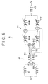
- Fig. 1 is a perspective view showing an entire deflection yoke which includes a raster rotation coil
- Fig. 2 is a side elevational view showing only coils and a DY core of the deflection yoke of Fig. 1.
- a pair of upper and lower saddle type horizontal deflection coils 3 are wound around a horizontal deflection coil bobbin 1.
- a pair of left and right saddle type vertical deflection coils 7 are wound around a vertical deflection coil bobbin 5 on the outer sides of the horizontal deflection coils 3.
- a DY core 9 made of ferrite is mounted such that it surrounds the vertical deflection coils 7.
- An annular (circular, polygonal or the like) raster rotation coil 11 is mounted along an outer periphery of the deflection yoke on the front side of the deflection yoke.
- the reference numeral 13 denotes an adjustment knob, 15 an adjustment coil, 17 a rear cover, and 19 a front cover.
- the raster rotation coil 11 has a winding of several hundred turns of a nylon-coated wire of a diameter of approximately ⁇ 0.2 to ⁇ 0.4 mm.
- the raster rotation coil 11 is usually used in order to correct rotation of a raster appearing on the screen of the cathode ray tube around an axis of the tube.
- the raster in an inclined state is corrected by a DC current flowing in the raster rotation coil.
- a magnetic field generated by the raster rotation coil interferes with the deflection coil.
- the magnetic field is fixed and it does not occur that an induction current flows in the deflection coil as a result of the interference. Consequently, a convergence characteristic is not influenced by the interference.
- This technique is effective to products for which a severe quality in regard to raster distortion is required, for example, to display units for computers.
- a pair of coils 21 wound on a shared core are respectively connected in series to two upper and lower horizontal deflection coils 23 and 25.
- the pair of coils have a strong magnetic connection since they share the core.
- the coils 21 connected in series to the two upper and lower horizontal deflection coils 23 and 25 have high inductance values only for an induction current generated by a variation of the magnetic field of the raster rotation coil.
- induction current flows in the deflection coils.
- the induction current is suppressed by the coils 21 connected in series to the upper side horizontal deflection coil 23 and the lower side horizontal deflection coil 25.
- the coils 21 have a function of suppressing induction current, they are called induction current suppressing coils.
- variable coils are connected in series to upper and lower side deflection coils as shown in Fig. 4C.
- variable coils are used in order to adjust the balance of the inductance value, and therefore called balance coils.
- the vertical asymmetry of the magnetic field can be adjusted by the difference in current. Accordingly, the vertical asymmetry of the deflection current can be corrected as shown in Fig. 4D, and the misconvergence illustrated in Fig. 4B can be corrected.
- the induction current suppressing coils 21 connected in series between the upper and lower side horizontal deflection coils and the upper and lower side balance coils have a strong magnetic connection and are connected in the opposite phases to each other.
- the induction current suppressing coils 21 act to cancel current variations of the upper and lower side horizontal deflection coils.
- a deflection yoke includes a pair of saddle type horizontal deflection coils and a pair of saddle type or troidal type vertical deflection coils and further includes an annular raster rotation coil centered at an axis of a cathode ray tube and provided on the front side of the deflection yoke.
- a pair of coils are respectively connected in series to the upper side horizontal deflection coil and the lower side horizontal deflection coil.
- the pair of coils are wound on a shared core and connected to the horizontal deflection coils such that the polarities of the coils may be opposite to each other. Consequently, the pair of coils have a strong magnetic connection.
- the coupling coefficient of the pair of coils is as high as possible.
- a single bias coil is wound on the core on which the pair of coils are wound. Part of the horizontal deflection current flows through the bias coil.
- the deflection yoke of the present invention is characterized in that a difference in current flowing through the upper side horizontal deflection coil and the lower side horizontal deflection coil is produced with the current which flows through the bias coil.
- the deflection yoke With the deflection yoke, if part of the horizontal deflection current flows into the bias coil, then this tends to generate magnetic fluxes inside the core of the pair of coils. At this time, induction current flows in the pair of coils having a strong magnetic connection so that the magnetic fluxes inside the core of the pair of coils may be canceled.
- the induction current varies the balance between the deflection current flowing through the upper side horizontal deflection coil and the current flowing through the lower side horizontal deflecting coil. Consequently, a difference is produced between the current which flows through the upper side horizontal deflection coil and the current which flows through the lower side horizontal deflection coil.
- the misconvergence arising from vertical asymmetry of the horizontal deflection magnetic fields can be corrected.
- a bridge circuit which includes four inductors can be used.
- An input terminal of the bridge circuit is connected to the low voltage sides of the horizontal deflection coils. Accordingly, as an input current, horizontal deflection current flows.
- a pair of output terminals of the bridge circuit are connected to the bias coil. The balance of the bridge circuit depends upon the values of the four inductors, and the amount and the direction of current flowing through the bias coil depend upon the balance.
- the inductance values of them can be adjusted freely.
- the amount and the direction of current flowing through the bias coil can be adjusted by adjustment of the variable inductors. Accordingly, the correction amount and the polarity of misconvergence can be adjusted.
- a non-linear inductor for the bridge circuit. For example, if a fixed bias magnetic field with a permanent magnet is applied to a coil, the inductance value of the coil indicates non-linearity.
- An inductor of the type just described is called a saturable reactor.
- an inductor whose bias magnetic field varies in response to the vertical deflection current may be used for the bridge circuit.
- operation of the bridge circuit varies also in response to the direction and the magnitude of the vertical deflection current.
- the current to be supplied to the bias coil need not always be part of the deflection current.
- a circuit for driving the bias coil may be provided in a receiver such that current is supplied from the circuit to the bias coil.
- a current of an arbitrary waveform can be supplied to the bias coil. Accordingly, the balance in the current between the upper side horizontal deflection coil and the lower side horizontal deflection coil can be varied arbitrarily.
- the deflection yoke 41 includes an induction current suppression coil 43 shown in Fig. 6 for suppressing induction current generated inside horizontal deflection coils.
- the induction current suppression coil 43 includes two stranded wires 47 and 49 wound commonly on a ring-shaped core 45 (for example. a ferrite core) of a diameter of approximately 10 to 30 mm.
- Each of the stranded wires 47 and 49 is composed of seven wires of a diameter of approximately 0.15 mm.
- the number of turns of each of the stranded wires 47 and 49 is approximately 5 to 20 turns.
- the specifications of the wire materials, numbers of turns and so forth of the core 45 and stranded wires 47 and 49 depend upon conditions in which the deflection yoke is used.
- the inductance values of the pair of coils 51 and 53 are high values such as approximately 0.5 to 3 mH.
- the inductance values of the pair of coils 51 and 53 are low values such as approximately 1 ⁇ H or less.
- a bias coil 55 of approximately 2 to 6 turns is wound around the core 45 of the induction current suppression coil 43.
- the opposite ends of the bias coil 55 are connected to terminals T5 and T6.
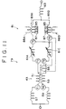
- the induction current suppression coil 43 is connected to horizontal deflection coils with such a connection as shown in Fig. 5.
- the deflection yoke 41 includes a pair of saddle type horizontal deflection coils (upper side horizontal deflection coil 57 and lower side horizontal deflection coil 59) shown in Fig. 5.
- an annular (circular, polygonal or the like) raster rotation coil, not shown, is mounted on the front side of the deflection yoke in such a manner as to be centered at an axis of a cathode ray tube.
- the upper side horizontal deflection coil 57 and the lower side horizontal deflection coil 59 are connected at one ends thereof to each other.
- the other end of the upper side horizontal deflection coil 57 is connected to the terminal T1 of the coil 51.
- the other end of the lower side horizontal deflection coil 59 is connected to the terminal T4 of the coil 53.
- the coils 51 and 53 have inductance values of approximately 4 to 20 times the inductance values of the horizontal deflection coils, and the polarities thereof are opposite in phase to each other.
- the terminal T3 of the coil 51 and the terminal T2 of the coil 53 are connected to a bridge circuit 61.
- the bridge circuit 61 includes a parallel connection of a pair of variable inductors 61A and 61B connected in series and another pair of variable inductors 61C and 61D connected in series similarly.
- the bridge circuit 61 has a pair of input terminals and a pair of output terminals.
- One of the input terminals, namely the junction of the variable inductors 61A and 61C, is connected to the terminals T3 and T2 of the coils 51 and 53 while the other input terminal, namely the junction between the variable inductors 61B and 61D, is connected to a leakage magnetic field cancellation coil 63.
- the cancellation coil 63 is used to cancel a magnetic field leaking to the outside of the receiver.
- one of the output terminals namely the junction between the variable inductors 61A and 61B, is connected to the terminal T6 of the bias coil 55 while the other output terminal, namely the junction between the variable inductors 61C and 61D, is connected to the terminal T5 of the bias coil 55.
- the bridge circuit 61 is formed from the variable inductors 61A, 61B, 61C and 61D, a current flows in any direction through the bias coil 55.
- the induction current suppression coil 43 acts as a resistor which has little inductance.
- the resistance value of the induction current suppression coil 43 is sufficiently low because the number of turns of the coil is small. Accordingly, the resistance value can be practically ignored.
- induction current induced by an influence of the raster rotation coil flows in such a manner as to circulate in a closed loop which includes the horizontal deflection coils 57 and 59. Accordingly, the magnetic fields generated from the coils 51 and 53 overlap each other. and the induction current suppression coil 43 has a high inductance value. Accordingly, the coil 43 suppresses flow of the induction current. In other words, the induction current suppression coil 43 suppresses only that induction current generated by an influence of the raster rotation coil without having an influence on the deflection current at all.
- variable inductors 61A, 61B, 61C and 61D of the bridge circuit 61 are varied, then the balance of the bridge circuit 61 varies, and part of the horizontal deflection current flows into the bias coil 55. Consequently, the bias coil 55 tends to generate magnetic fluxes inside the core 45 of the induction current suppression coil 43. At this time, in the induction current suppression coil 43, induction current flows in a direction in which it prevents generation of magnetic fluxes inside the core 45. In other words, induction current is generated in the coils 51 and 53.
- the induction current flows in the closed circuit including in the deflection coils 57 and 59. Consequently, the induction current flows in the same direction as that of the deflection current in either one of the upper side horizontal deflection coil 57 and the lower side horizontal deflection coil 59, but flows in the opposite direction to that of the deflection current in the other side of them.
- the induction current varies the balance of the current flowing through the deflection coils 57 and 59.
- a deflection yoke 69 uses a bridge circuit 71 in place of the bridge circuit 61 described above.
- the bridge circuit 71 includes saturable reactors 73a and 73d in place of the variable inductors 61A and 61D (refer to Fig. 5) which are components of the bridge circuit 61.
- Each of the saturable reactors 73a and 73d is composed of an inductor 75 and a permanent magnet 77.
- the inductance value of the saturable reactor varies non-linearly.
- the construction of the remaining part of the deflection yoke 69 is similar to that of the deflection yoke 41 described above.
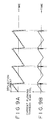
- the balance of the bridge circuit 71 varies in response to the magnitude and the direction of the horizontal deflection current by means of the saturable reactors 73A and 73D. Consequently, a parabolic current can be generated in the bridge circuit 71.
- a current of a waveform shown in Fig. 9B is supplied to the bias coil 55, the horizontal deflection current has a waveform as shown in Fig. 9A. Consequently, the correction of misconvergence called XV illustrated in Fig. 10 is allowed.
- a deflection yoke 79 according to the modification 2 to the first embodiment of the deflection yoke according to the present invention.
- a bridge circuit 81 is used in place of the bridge circuit 61 described above.
- the bridge circuit 81 includes saturable reactors 83b and 83d in place of the variable inductors 61B and 61D (refer to Fig. 5) which are components of the bridge circuit 61.
- Each of the saturable reactors 83b and 83d includes an inductor 85 and a permanent magnet 87, and a vertical deflection current is supplied to coils 88A and 88B to apply bias magnetic fields to the saturable reactors 83B and 83D.
- the construction of the remaining part of the deflection yoke 79 is similar to that of the deflection yoke 41 described above.
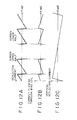
- the inductance values of the saturable reactors 83b and 83d are modulated with vertical deflection current of a waveform shown in Fig. 12C. Consequently, the balance of the bridge circuit 81 varies in response to the magnitude and the direction of the vertical deflection current. Accordingly, a current of a waveform shown in Fig. 12B can be supplied from the bridge circuit 81 to the bias coil 55 to correct the wavefonn of the deflection current to that shown in Fig. 12A. Consequently, the correction of misconvergence called PQV illustrated in Fig. 13 is allowed.
- a second embodiment of a deflection yoke according to the present invention is described with reference to Fig. 14.
- the bridge circuit 61 shown in Fig. 5 is omitted, and the terminals T3 and T2 of the coils 51 and 53 are connected to each other, and a leakage magnetic field cancellation coil 63 is connected to the junction of the terminals T3 and T2.
- a bias coil 55 is provided for the core 45 in a similar manner as described above.
- a current for example, of a waveform similar to that shown in Fig. 9A described above or a waveform shown in Fig.
- the deflection yoke 89 magnetic fluxes can be generated inside the core 45 of the induction current suppression coil 43 with the composed current to vary the balance of the currents flowing through the upper side horizontal deflection coil 57 and the lower side horizontal deflection coil 59.
- the waveform can be adjusted freely in accordance with the characteristic of the cathode ray tube or the deflection yoke to perform the misconvergence correction readily without using an expensive saturable reactor.
- the induction current suppression coils connected to the horizontal deflection coils of each of the deflection coils 41, 69, 79 and 89 described above is constructed such that a stranded wire is wound on a core of a ring shape
- the coil is not limited to this and may include a C-shaped or E-shaped core.
- a solid wire may be used for the coil.
- one of two input terminals of each of the bridge circuits 61, 71 and 81 is connected to a leakage magnetic field cancellation coil.
- the cancellation coil may be omitted. in this instance, the input terminal is connected directly to a deflection circuit of the receiver.
- the suppression of induction current induced from a raster rotation coil and the correction of misconvergence performed by producing a difference in current between an upper side horizontal deflection coil and a lower side horizontal deflection coil can be achieved simultaneously.
- a waveform can be adjusted freely to perform a misconvergence correction readily without using an expensive saturable reactor.
Landscapes
- Video Image Reproduction Devices For Color Tv Systems (AREA)
Applications Claiming Priority (2)
| Application Number | Priority Date | Filing Date | Title |
|---|---|---|---|
| JP10216716A JP2000048739A (ja) | 1998-07-31 | 1998-07-31 | 偏向ヨーク |
| JP21671698 | 1998-07-31 |
Publications (3)
| Publication Number | Publication Date |
|---|---|
| EP0977238A2 true EP0977238A2 (de) | 2000-02-02 |
| EP0977238A3 EP0977238A3 (de) | 2001-08-08 |
| EP0977238B1 EP0977238B1 (de) | 2005-06-01 |
Family
ID=16692810
Family Applications (1)
| Application Number | Title | Priority Date | Filing Date |
|---|---|---|---|
| EP99401947A Expired - Lifetime EP0977238B1 (de) | 1998-07-31 | 1999-07-30 | Ablenkjoch für eine Kathodenstrahlröhre |
Country Status (5)
| Country | Link |
|---|---|
| US (1) | US6218773B1 (de) |
| EP (1) | EP0977238B1 (de) |
| JP (1) | JP2000048739A (de) |
| KR (1) | KR20000012069A (de) |
| DE (1) | DE69925542T2 (de) |
Families Citing this family (6)
| Publication number | Priority date | Publication date | Assignee | Title |
|---|---|---|---|---|
| JP2001256904A (ja) * | 2000-03-08 | 2001-09-21 | Sony Corp | 偏向装置及び陰極線管装置並びにビームランディング調整方法 |
| JP2001332185A (ja) * | 2000-05-24 | 2001-11-30 | Toshiba Corp | 陰極線管装置 |
| KR100376996B1 (ko) * | 2000-06-26 | 2003-03-26 | 삼성전기주식회사 | 수평 코일의 불균형 제어 개선 방법 |
| JP2002093346A (ja) * | 2000-09-11 | 2002-03-29 | Mitsubishi Electric Corp | 偏向ヨーク装置 |
| US6617779B1 (en) | 2001-10-04 | 2003-09-09 | Samuel A. Schwartz | Multi-bend cathode ray tube |
| KR101440177B1 (ko) | 2007-10-02 | 2014-09-12 | 가부시끼가이샤 에스애취티 | 코일 장치 및 그 제조 방법 |
Family Cites Families (6)
| Publication number | Priority date | Publication date | Assignee | Title |
|---|---|---|---|---|
| US5250876A (en) * | 1989-07-14 | 1993-10-05 | U.S. Philips Corporation | Display tube and deflection unit suitable for such a display tube |
| TW270998B (de) * | 1992-04-17 | 1996-02-21 | Toshiba Co Ltd | |
| JP3320543B2 (ja) * | 1994-01-31 | 2002-09-03 | 松下電器産業株式会社 | 受像管装置及びそのラスタ歪補正方法 |
| US5644197A (en) * | 1995-03-22 | 1997-07-01 | International Business Machines Corporation | Cathode ray tube display apparatus with rotatable raster |
| JPH0965352A (ja) * | 1995-08-23 | 1997-03-07 | Nec Kansai Ltd | 陰極線管装置 |
| JPH10188847A (ja) * | 1996-12-19 | 1998-07-21 | Sony Corp | 分割型コイルセパレータ |
-
1998
- 1998-07-31 JP JP10216716A patent/JP2000048739A/ja active Pending
-
1999
- 1999-07-21 US US09/357,943 patent/US6218773B1/en not_active Expired - Fee Related
- 1999-07-29 KR KR1019990031037A patent/KR20000012069A/ko not_active Withdrawn
- 1999-07-30 EP EP99401947A patent/EP0977238B1/de not_active Expired - Lifetime
- 1999-07-30 DE DE69925542T patent/DE69925542T2/de not_active Expired - Fee Related
Also Published As
| Publication number | Publication date |
|---|---|
| DE69925542D1 (de) | 2005-07-07 |
| US6218773B1 (en) | 2001-04-17 |
| EP0977238B1 (de) | 2005-06-01 |
| KR20000012069A (ko) | 2000-02-25 |
| DE69925542T2 (de) | 2006-04-27 |
| JP2000048739A (ja) | 2000-02-18 |
| EP0977238A3 (de) | 2001-08-08 |
Similar Documents
| Publication | Publication Date | Title |
|---|---|---|
| US6265836B1 (en) | Image distortion compensating apparatus | |
| EP0542304B1 (de) | Ablenkeinheit für Elektronenstrahlröhren und Farbstrahlröhre mit einer solchen Ablenkeinheit | |
| EP0977238B1 (de) | Ablenkjoch für eine Kathodenstrahlröhre | |
| EP1301029A2 (de) | Vorrichtung zur Korrektur von Kissenverzerrungen | |
| US5350980A (en) | Nonlinear inductor with magnetic field reduction | |
| USRE35183E (en) | Deflection yoke for use in color cathode ray tubes | |
| US5668447A (en) | Deflection yoke and cathode-ray tube apparatus comprising the same | |
| US4198614A (en) | Deflection yoke assembly including a beam positioning magnet arrangement | |
| JPH07114116B2 (ja) | インライン型カラ−受像管用偏向ヨ−ク | |
| US6326745B1 (en) | Cathode-ray tube apparatus | |
| KR100226248B1 (ko) | 콘버어젠스 보정장치 | |
| US6252359B1 (en) | Deflection apparatus | |
| JPH03232387A (ja) | カラー陰極線管ディスプレイ装置 | |
| JP2000048740A (ja) | 偏向ヨーク | |
| KR100355852B1 (ko) | 편향요크의 미스 컨버젼스 보정장치 | |
| KR100786852B1 (ko) | 편향 요크의 미스컨버젼스 보정장치 | |
| JP2003016969A (ja) | ミスコンバーゼンス補正装置およびカラー画像表示装置 | |
| JP2000200565A (ja) | 偏向ヨ―ク | |
| JPS6384287A (ja) | カラ−陰極線管用偏向装置 | |
| JPH0730909A (ja) | 横ミスコンバージェンス補正回路 | |
| JPH0564412B2 (de) | ||
| JPH0562417B2 (de) | ||
| JPH07203469A (ja) | カラー陰極線管ディスプレイ装置 | |
| JP2004015682A (ja) | コンバージェンス補正装置、偏向ヨーク及び表示装置 | |
| JPH0738903A (ja) | コンバージェンス補正回路 |
Legal Events
| Date | Code | Title | Description |
|---|---|---|---|
| PUAI | Public reference made under article 153(3) epc to a published international application that has entered the european phase |
Free format text: ORIGINAL CODE: 0009012 |
|
| AK | Designated contracting states |
Kind code of ref document: A2 Designated state(s): DE FR GB |
|
| AX | Request for extension of the european patent |
Free format text: AL;LT;LV;MK;RO;SI |
|
| PUAL | Search report despatched |
Free format text: ORIGINAL CODE: 0009013 |
|
| AK | Designated contracting states |
Kind code of ref document: A3 Designated state(s): AT BE CH CY DE DK ES FI FR GB GR IE IT LI LU MC NL PT SE |
|
| AX | Request for extension of the european patent |
Free format text: AL;LT;LV;MK;RO;SI |
|
| 17P | Request for examination filed |
Effective date: 20020205 |
|
| AKX | Designation fees paid |
Free format text: DE FR GB |
|
| 17Q | First examination report despatched |
Effective date: 20030903 |
|
| GRAP | Despatch of communication of intention to grant a patent |
Free format text: ORIGINAL CODE: EPIDOSNIGR1 |
|
| GRAS | Grant fee paid |
Free format text: ORIGINAL CODE: EPIDOSNIGR3 |
|
| GRAA | (expected) grant |
Free format text: ORIGINAL CODE: 0009210 |
|
| AK | Designated contracting states |
Kind code of ref document: B1 Designated state(s): DE FR GB |
|
| REG | Reference to a national code |
Ref country code: GB Ref legal event code: FG4D |
|
| REF | Corresponds to: |
Ref document number: 69925542 Country of ref document: DE Date of ref document: 20050707 Kind code of ref document: P |
|
| PLBE | No opposition filed within time limit |
Free format text: ORIGINAL CODE: 0009261 |
|
| STAA | Information on the status of an ep patent application or granted ep patent |
Free format text: STATUS: NO OPPOSITION FILED WITHIN TIME LIMIT |
|
| ET | Fr: translation filed | ||
| 26N | No opposition filed |
Effective date: 20060302 |
|
| PGFP | Annual fee paid to national office [announced via postgrant information from national office to epo] |
Ref country code: DE Payment date: 20080814 Year of fee payment: 10 |
|
| PGFP | Annual fee paid to national office [announced via postgrant information from national office to epo] |
Ref country code: FR Payment date: 20080718 Year of fee payment: 10 |
|
| PGFP | Annual fee paid to national office [announced via postgrant information from national office to epo] |
Ref country code: GB Payment date: 20080806 Year of fee payment: 10 |
|
| GBPC | Gb: european patent ceased through non-payment of renewal fee |
Effective date: 20090730 |
|
| REG | Reference to a national code |
Ref country code: FR Ref legal event code: ST Effective date: 20100331 |
|
| PG25 | Lapsed in a contracting state [announced via postgrant information from national office to epo] |
Ref country code: FR Free format text: LAPSE BECAUSE OF NON-PAYMENT OF DUE FEES Effective date: 20090731 |
|
| PG25 | Lapsed in a contracting state [announced via postgrant information from national office to epo] |
Ref country code: GB Free format text: LAPSE BECAUSE OF NON-PAYMENT OF DUE FEES Effective date: 20090730 |
|
| PG25 | Lapsed in a contracting state [announced via postgrant information from national office to epo] |
Ref country code: DE Free format text: LAPSE BECAUSE OF NON-PAYMENT OF DUE FEES Effective date: 20100202 |