EP0977680B1 - Palier pour essiue-glace - Google Patents
Palier pour essiue-glace Download PDFInfo
- Publication number
- EP0977680B1 EP0977680B1 EP99934220A EP99934220A EP0977680B1 EP 0977680 B1 EP0977680 B1 EP 0977680B1 EP 99934220 A EP99934220 A EP 99934220A EP 99934220 A EP99934220 A EP 99934220A EP 0977680 B1 EP0977680 B1 EP 0977680B1
- Authority
- EP
- European Patent Office
- Prior art keywords
- bearing
- seal
- bearing housing
- axial
- wiper
- Prior art date
- Legal status (The legal status is an assumption and is not a legal conclusion. Google has not performed a legal analysis and makes no representation as to the accuracy of the status listed.)
- Expired - Lifetime
Links
- 230000001681 protective effect Effects 0.000 claims description 35
- 239000004033 plastic Substances 0.000 claims description 10
- 238000007789 sealing Methods 0.000 claims description 10
- 239000013013 elastic material Substances 0.000 claims description 4
- 239000000463 material Substances 0.000 description 9
- 230000002349 favourable effect Effects 0.000 description 4
- XLYOFNOQVPJJNP-UHFFFAOYSA-N water Substances O XLYOFNOQVPJJNP-UHFFFAOYSA-N 0.000 description 4
- 239000003344 environmental pollutant Substances 0.000 description 3
- 231100000719 pollutant Toxicity 0.000 description 3
- 229910001018 Cast iron Inorganic materials 0.000 description 2
- 230000037431 insertion Effects 0.000 description 2
- 238000003780 insertion Methods 0.000 description 2
- 238000009434 installation Methods 0.000 description 2
- 230000007257 malfunction Effects 0.000 description 2
- 239000007787 solid Substances 0.000 description 2
- 239000000126 substance Substances 0.000 description 2
- HCHKCACWOHOZIP-UHFFFAOYSA-N Zinc Chemical compound [Zn] HCHKCACWOHOZIP-UHFFFAOYSA-N 0.000 description 1
- XAGFODPZIPBFFR-UHFFFAOYSA-N aluminium Chemical compound [Al] XAGFODPZIPBFFR-UHFFFAOYSA-N 0.000 description 1
- 229910052782 aluminium Inorganic materials 0.000 description 1
- 239000000356 contaminant Substances 0.000 description 1
- -1 dirt Substances 0.000 description 1
- 230000007613 environmental effect Effects 0.000 description 1
- 238000004519 manufacturing process Methods 0.000 description 1
- 229920000642 polymer Polymers 0.000 description 1
- 230000002940 repellent Effects 0.000 description 1
- 239000005871 repellent Substances 0.000 description 1
- 150000003839 salts Chemical class 0.000 description 1
- 239000007921 spray Substances 0.000 description 1
- 230000003068 static effect Effects 0.000 description 1
- 229910052725 zinc Inorganic materials 0.000 description 1
- 239000011701 zinc Substances 0.000 description 1
Images



Classifications
-
- B—PERFORMING OPERATIONS; TRANSPORTING
- B60—VEHICLES IN GENERAL
- B60S—SERVICING, CLEANING, REPAIRING, SUPPORTING, LIFTING, OR MANOEUVRING OF VEHICLES, NOT OTHERWISE PROVIDED FOR
- B60S1/00—Cleaning of vehicles
- B60S1/02—Cleaning windscreens, windows or optical devices
- B60S1/04—Wipers or the like, e.g. scrapers
- B60S1/06—Wipers or the like, e.g. scrapers characterised by the drive
- B60S1/16—Means for transmitting drive
- B60S1/18—Means for transmitting drive mechanically
-
- B—PERFORMING OPERATIONS; TRANSPORTING
- B60—VEHICLES IN GENERAL
- B60S—SERVICING, CLEANING, REPAIRING, SUPPORTING, LIFTING, OR MANOEUVRING OF VEHICLES, NOT OTHERWISE PROVIDED FOR
- B60S1/00—Cleaning of vehicles
- B60S1/02—Cleaning windscreens, windows or optical devices
- B60S1/04—Wipers or the like, e.g. scrapers
- B60S1/32—Wipers or the like, e.g. scrapers characterised by constructional features of wiper blade arms or blades
- B60S1/34—Wiper arms; Mountings therefor
-
- B—PERFORMING OPERATIONS; TRANSPORTING
- B60—VEHICLES IN GENERAL
- B60S—SERVICING, CLEANING, REPAIRING, SUPPORTING, LIFTING, OR MANOEUVRING OF VEHICLES, NOT OTHERWISE PROVIDED FOR
- B60S1/00—Cleaning of vehicles
- B60S1/02—Cleaning windscreens, windows or optical devices
- B60S1/04—Wipers or the like, e.g. scrapers
- B60S1/06—Wipers or the like, e.g. scrapers characterised by the drive
- B60S1/16—Means for transmitting drive
-
- B—PERFORMING OPERATIONS; TRANSPORTING
- B60—VEHICLES IN GENERAL
- B60S—SERVICING, CLEANING, REPAIRING, SUPPORTING, LIFTING, OR MANOEUVRING OF VEHICLES, NOT OTHERWISE PROVIDED FOR
- B60S1/00—Cleaning of vehicles
- B60S1/02—Cleaning windscreens, windows or optical devices
- B60S1/04—Wipers or the like, e.g. scrapers
- B60S1/32—Wipers or the like, e.g. scrapers characterised by constructional features of wiper blade arms or blades
- B60S1/34—Wiper arms; Mountings therefor
- B60S1/3488—Means for mounting wiper arms onto the vehicle
- B60S1/3493—Means for mounting the wiper shaft in the wiper bearing
-
- B—PERFORMING OPERATIONS; TRANSPORTING
- B60—VEHICLES IN GENERAL
- B60S—SERVICING, CLEANING, REPAIRING, SUPPORTING, LIFTING, OR MANOEUVRING OF VEHICLES, NOT OTHERWISE PROVIDED FOR
- B60S1/00—Cleaning of vehicles
- B60S1/02—Cleaning windscreens, windows or optical devices
- B60S1/04—Wipers or the like, e.g. scrapers
- B60S1/32—Wipers or the like, e.g. scrapers characterised by constructional features of wiper blade arms or blades
- B60S1/34—Wiper arms; Mountings therefor
- B60S1/3425—Constructional aspects of the arm
- B60S1/3443—Wiper shafts
Definitions
- the invention relates to a wiper bearing according to the preamble of claim 1.
- Wiper systems with multiple windscreen wipers for motor vehicles become with their wiper bearing directly or indirectly over a board attached to the body of the motor vehicle.
- the board carries a wiper drive with a wiper motor, whose motor shaft drives via a linkage cranks, with one end of a drive shaft for each windshield wiper are firmly connected. It is also possible that only the Drive shaft of a windshield wiper driven by the wiper motor while another wiper is over Four-bar linkage connected to the first windscreen wiper is and has a bearing axis.
- the drive shaft or the bearing axis is stored in a wiper bearing. in the The following apply to a drive shaft also for a bearing axis mutatis mutandis, because of the simplification no longer explicitly mentioned.
- a wiper bearing in which in the bearing housing at least one radial bearing and on the End faces between the bearing housing and one with the drive shaft rotatably connected part, z. B. starting rings or a stop ring and a crank plate of the crank, axial bearings are provided.
- the drive shaft usually protrudes from a body of a motor vehicle and moving a windshield wiper attached at its free end over a windshield.
- Substances such as dirt, water, aggressive dissolved in water Substances such as salt and air contaminants in the bearing column and destroying the bearings, the bearing gaps become smaller sealed on the outside.
- the known bearing housing has for this purpose at one end face towards the drive shaft towards a free space in which an O-ring is arranged, which is biased to the thrust ring and abuts the bearing housing and on the drive shaft.
- the bearing housing extends over the radial bearing surfaces out, through recesses in the Area of the end faces of the bearing housing of the free space formed becomes.
- plastic bearing housings is the free space formed. Such seals extend the axial Warrekkung of the bearing housing, protect only the radial bearings and have a relatively high friction.
- the seal is at a radial distance arranged to the radial bearing outside of the axial bearing and the bearing gaps of the axial and radial bearings are sealed to the outside, so compared to the known Solution with an O-ring in addition to the radial bearings in addition the axial bearings are protected from pollutants.
- This is particularly advantageous in bearing housings made of plastic, because of their low cost and their small weight increasingly used, but often less resistant against water and pollutants are as z.
- the seal assembly according to the invention claimed no additional axial space, so that the Available space for a long bearing base of the radial Bearings can be used.
- high Transverse forces absorbed at low, specific material load become.
- softer materials, such as Plastic even with a long life be used.
- the seal is rotationally fixed connected to the bearing housing and is located with an axial acting sealing lip on the stop ring or the crank plate in the outer, radially adjoining the axial bearing Area on.
- seal is preferably an axial lip seal used.
- the lip seal can with a low pressure, a small Gleitreib Simulation and thus be sealed well with a low sliding friction.
- the Lip seal has a small wear in continuous operation and a wiper drive must at startup due to a small static friction apply only small breakaway forces. Possible is also a non-contact instead of a lip seal To use a seal, for example a labyrinth seal, whereby the sliding friction for the seal is complete eliminated.
- the seal is expediently in a recess of the Bearing housing arranged.
- the bearing housing which is usually made of cast iron exists, pressed bearing bushes, z. B. of sintered material.
- At one or both ends of the bearing sleeves protrude over the bearing housing and form next to radial bearings at the same time bearing surfaces for axial bearings on a thrust ring or a crank plate of the drive shaft.
- a recess thereby occurs between the bearing housing and the stop ring or the crank plate a recess, in the favorable the seal can be accommodated.
- a radial Bearing can be achieved, which has a large axial bearing base features.
- a favorable material used for the radial bearing is used simultaneously for the axial bearing, whereby low achieved low friction on the axial bearing can be.
- bearing housing and the seal as a two-component component, i. from a solid Plastic part and a soft seal, for example Lip seal.
- a solid Plastic part and a soft seal for example Lip seal.
- a protective cap on the drive shaft, the outwardly protruding from the body end of the Bearing housing encloses.
- the protective cap is used simultaneously, a radial sealing surface to form a radial seal, the seals the axial and the radial bearing of the drive shaft. In the area of the axial bearing thereby eliminates the recess for the gasket, making them at almost the same radial Installation space can be made larger.
- the protective cap can preferably with the seal as a two-component component or designed as a one-piece component made of rubber-elastic material become.
- the individual components and the installation effort are thus reduced.
- the protective cap is on the shaft pressed and / or according to an embodiment the invention via a shaft groove with this latched, thereby the protective cap is quickly and accurately positioned during assembly can be, after mounting in both axial directions is securely fixed and does not slip in use, which would lead to a malfunction of the seal.
- the seal is preferably a lip seal, as well other types of seals are possible alone or in addition, which can act axially and / or radially, such as non-contact labyrinth seals.
- a joining bevel To protect the cap easily to mount without damaging the seal and / or fold, have the bearing housing in the mounting direction a joining bevel.
- a further embodiment of the invention consists in the side of the crank plate a rubber boot on the bearing housing to fix.
- the rubber boot is supported preferably in a first, repellent from the axial bearing Direction to the bearing housing and in a second axial Direction on the crank plate or on a stop ring, and seals the radial and the axial bearing to the outside.
- Fig. 1 shows a bearing housing 10 of a wiper bearing made of cast iron with two pressed bearing bushes 84, 86 made of sintered material.
- the bearing housing 10 and the bearing bushes 84, 86th can also be made of different materials and in connected in various ways, for example by a non-positive, positive and / or through a cohesive connection.
- the bushings 84, 86 is a drive shaft 24 via two radial bearings 30, 32 stored in the form of plain bearings.
- the drive shaft 24 is supported in a first axial direction 110 with a rotatable clamping ring 108 via a stop ring 36 on a first axial bearing 42 from whose one bearing surface of a End face of the bearing bush 84 is formed.
- the drive shaft 24 is supported by a Crank 38 from a second axial bearing 48 from.
- the axial bearings 42, 48 are formed as sliding bearings.
- the bearing housing 10 is in a tubular recess a non-illustrated, permanently connected to a vehicle Board attached.
- the drive shaft 24 protrudes with a End 114 of the vehicle body on which a windshield wiper is attached. Will be a fully assembled wiper system actuated, drives a motor via a motor shaft, a linkage, a ball joint 116 and over the crank plate 38, the associated drive shaft 24, which the windshield wiper moved over a windshield.
- the bearing housing 10 is sealed on the outside, in particular on the side, to the protruding from the body end 114th has.
- the bearing bush 84 projects beyond the end face 88 of the bearing housing 10 and forms next to the radial Bearing 30, the axial bearing 42 for the drive shaft 24.
- Die Drive shaft 24 is in the axial direction 110 with less Friction stored on the bearing bush 84.
- a gap 118, in the low axial lip seal 62th can be used with an axially acting lip 82.
- the lip seal 62 seals the axial bearing 42 and the radial Bearing 30 to the end 114 of the drive shaft 24 to the outside from. Wear is reduced and life increases, especially with low axial bearing clearance.
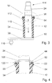
- FIGS. 3 to 15 are bearing housings 12, 14, 16, 18, 20, 22 124 shown in plastic, wherein the bearing surfaces of Bearings 34, 44, 46, 50 52, 54, 56, 58, 60 directly on the bearing housing 12, 14, 16, 18, 20, 22 124 are provided.
- the bearing housing 12 in Fig. 3 has in the radially outer region of an axial Bearings 44 in the direction 112 to the end 114 of the drive shaft 24 a recess 120 into which an axial lip seal 64th is pressed. It is also possible, the lip seal 64 with other positive, non-positive and / or cohesive To secure connections in the bearing housing 12.
- the bearing housing 12 has in the region of the lip seal 64 has a higher wall thickness, so that despite the recess 120, a sufficiently large axial bearing 44 is achieved.
- the recess 120 protects the lip seal 64 with a Footbridge 122 from external influences, for example, that the lip seal 64 is damaged during assembly.
- the lip seal 64 seals the axial bearing 44 and the radial bearing 34 to the end 114 of the drive shaft 24 to the outside. Camps 34, 44 are protected from environmental influences and it can entire length of the bearing housing 12 for a bearing base of the radial bearing 34 can be used. This allows the bearing housing 12 large lateral forces are absorbed without the radial bearing 34 deflects.
- Fig. 4 shows one as IV Enlarged section enlarged.
- the bearing housing 14 and a seal 66 of formed a two-component component In Fig. 5, the bearing housing 14 and a seal 66 of formed a two-component component.
- the seal 66 seals an axial bearing 46 and the radial bearing 34 to the outside from.
- the individual components are reduced and thus the Production costs and / or assembly costs.
- the drive shaft 24 is supported in the direction 112 with the crank plate 38 on an axial bearing 50 from which is not additionally sealed to the outside.
- the bearing 54 between the crank plate 38 and the bearing housing 16 is sealed in accordance with one of the seal 68 shown in Figs. 3 and 4 in the embodiment in Fig. 6.
- all solutions according to the invention can in principle be used on both sides of the bearing housing.
- the solutions according to the invention can also be used with a crank plate 40 arranged on top (FIG. 7).
- a drive shaft 26 is axially fixed in the direction 112 to the body protruding end 114 with a ring 130 via a first lower axial bearing 52 and the crank plate 40 via a second upper axial bearing 44.
- the upper bearing 44 between the crank plate 40 and the bearing housing 18 is sealed to the outside according to the embodiment described in FIGS. 3 and 4.
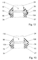
- Fig. 8 shows an embodiment with a protective cap 90 which is rotatably connected to the drive shaft 24 and projects beyond the end face of the bearing housing 20 in the direction 110 of the crank plate 38.
- the protective cap 90 is supported in the mounting direction 110 on the clamping ring 108 and can thereby be positioned quickly and accurately during assembly.
- a radial lip seal 70 is arranged, which is rotatably connected to the protective cap 90.
- An axial bearing 58 and the radial bearing 34 are sealed with the lip seal 70 on a radial sealing surface 132 of the bearing housing 20 to the outside.
- the drive shaft 24 is shapely designed by the protective cap 90, protected from direct spray and in particular the entire wall thickness of the bearing housing 20 can be used as a bearing surface of the axial bearing 54 (Fig. 8, 9).
- the bearing housing 124 in Fig. 10 in the mounting direction 110 of the protective cap 90 has a Fugeschräge 102nd
- FIG. 11 shows an enlarged detail XI from FIG. 8.
- a rubber boot 72 arranged to the crank plate 38 to the crank plate 38.
- the rubber sleeve 72 is supported in the direction 112 at an integrally formed projection 126 of the bearing housing 20 and in direction 110 on the crank plate 38 and on a stop ring 106 from. It seals an axial bearing 56 between the bearing housing 20 and the thrust ring 106th and the radial bearing 34 to the outside safely.
- a solid plastic protective cap 92 with a rubber-elastic seal 74th designed as a two-component component, which at a radial Sealing surface 134, an axial bearing 60 and the radial bearing 34th caulk.
- a joining bevel 104 To the protective cap 92 with the seal 74 safely to be able to mount without the seal 74 damaged is, has the bearing housing 22 in the mounting direction 110 of the Protective cap 92 a joining bevel 104.
- Fig. 13 is a Protective cap 98 and a seal 76 integrally made of rubber-elastic Material shown.
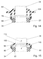
- FIG. 14 shows a protective cap 94 with a seal 78 as a two-component component.
- the protective cap 94 has a radially extending Projection 128, with the favorable mounting hole in the Vehicle body can be closed.
- a protective cap 96 with a seal 80 in a shaft recess 100 of a drive shaft 28 locked The designed as a two-component component Protective cap 96 is safe in both after assembly axial directions 110, 112 fixed. The protective cap 96 slips not, what else to a malfunction of the seal 80 can lead.
Landscapes
- Engineering & Computer Science (AREA)
- Mechanical Engineering (AREA)
- Sealing Of Bearings (AREA)
- Mounting Of Bearings Or Others (AREA)
Claims (11)
- Palier d'essuie-glace comprenantcaractérisé en ce queun boítier de palier (10, 12, 14, 16, 18, 20, 22, 124) dans lequel est monté un arbre d'entraínement (24, 26, 28) avec un palier radial (30, 32, 34), en étant guidé du côté frontal par une bague d'arrêt (36, 106) et par une plaque de manivelle (38, 40) qui sont solidaires de l'arbre d'entraínement (24, 26, 28) et forment, avec le boítier de palier, directement ou indirectement, des paliers axiaux (42, 44, 46, 48, 50, 52, 54, 56, 58, 60),un joint d'étanchéité (62, 64, 66, 68, 70, 72, 74, 76, 78, 80) assurant l'étanchéité entre le boítier de palier (10, 12, 14, 16, 18, 20, 22, 124) et une partie (36, 106, 38, 40, 90, 92, 94, 96, 98) solidaire de l'arbre d'entraínement (24, 26, 28), ce joint étant monté à l'extérieur du palier axial (42, 44, 46, 48, 50, 52, 54, 56, 58, 60) à une certaine distance radiale du palier radial (30, 32, 34),
le joint d'étanchéité (62, 64, 66, 68, 70, 72, 74, 76, 78, 80) assure l'étanchéité par rapport à l'extérieur des fentes des paliers axiaux et radiaux (42, 44, 46, 48, 50, 52, 54, 56, 58, 60 ; 30, 32, 34). - Palier d'essuie-glace selon la revendication 1,
caractérisé en ce que
le joint d'étanchéité (62, 64, 66, 72) est solidaire du boítier de palier (10, 12, 14, 16, 18, 20) et est en contact avec une lèvre d'étanchéité (82) agissant axialement sur la bague d'arrêt (36, 106) ou sur la plaque de manivelle (38, 40) dans la zone extérieure faisant suite radialement au palier axial (42, 44, 46, 54, 56). - Palier d'essuie-glace selon la revendication 2,
caractérisé en ce que
le boítier de palier (10) présente des douilles de palier (84, 86) emmanchées à force dans le boítier de palier (10), et au moins une de ces douilles fait saillie sur la face frontale (88) du boítier de palier (10) et sa face frontale constitue une portée de palier pour les paliers axiaux (42) montés sur la bague d'arrêt (36) ou sur la plaque de manivelle (38), le joint d'étanchéité (62) étant monté entre la face frontale (88) du boítier de palier (10) et la bague d'arrêt (36) ou la plaque de manivelle (38). - Palier d'essuie-glace selon une des revendications précédentes,
caractérisé en ce que
le boítier de palier (12, 14, 16, 18, 20, 22, 124) est en matière plastique. - Palier d'essuie-glace selon la revendication 4,
caractérisé en ce que
le boítier de palier (14) et le joint d'étanchéité (66) sont réalisés sous la forme d'un élément à deux composants. - Palier d'essuie-glace selon une des revendications précédentes,
caractérisé en ce qu'
un capot de protection (90, 92, 94, 96, 98) est solidaire en rotation et avec étanchéité, de l'arbre d'entraínement (24), et entre le capot (90, 92, 94, 96, 98) et le boítier de palier (20, 22, 124) est monté un joint radial d'étanchéité (70, 74, 76, 78, 80). - Palier d'essuie-glace selon la revendication 6,
caractérisé en ce que
le capot de protection (92, 94, 96) et le joint d'étanchéité (74, 78, 80) sont réalisés sous la forme d'un élément à deux composants. - Palier d'essuie-glace selon la revendication 6,
caractérisé en ce que
le capot de protection (98) et le joint d'étanchéité (76) constituent une seule pièce en matériau élastique comme du caoutchouc. - Palier d'essuie-glace selon une des revendications 6 à 8,
caractérisé en ce que
le capot de protection (96) est bloqué dans une entaille de l'arbre (100). - Palier d'essuie-glace selon une des revendications 6 à 9,
caractérisé en ce que
le boítier de palier (124, 22) présente sur sa face frontale dirigée vers le capot de protection (90, 92, 94, 96, 98) un chanfrein de jonction (102, 104). - Palier d'essuie-glace selon une des revendications précédentes,
caractérisé en ce que
du côté de la plaque de manivelle (38) est fixée une manchette en caoutchouc (72) sur le palier de boítier (20), et cette manchette assure l'étanchéité par rapport à l'extérieur du palier axial (56) et du palier radial (34) en étant appliquée sur une bague d'arrêt (106) ou sur la plaque de manivelle (38).
Applications Claiming Priority (3)
| Application Number | Priority Date | Filing Date | Title |
|---|---|---|---|
| DE19804135 | 1998-02-03 | ||
| DE19804135A DE19804135B4 (de) | 1998-02-03 | 1998-02-03 | Wischerlager |
| PCT/DE1999/000114 WO1999039945A1 (fr) | 1998-02-03 | 1999-01-20 | Palier d'essuie-glace |
Publications (2)
| Publication Number | Publication Date |
|---|---|
| EP0977680A1 EP0977680A1 (fr) | 2000-02-09 |
| EP0977680B1 true EP0977680B1 (fr) | 2005-07-27 |
Family
ID=7856474
Family Applications (1)
| Application Number | Title | Priority Date | Filing Date |
|---|---|---|---|
| EP99934220A Expired - Lifetime EP0977680B1 (fr) | 1998-02-03 | 1999-01-20 | Palier pour essiue-glace |
Country Status (8)
| Country | Link |
|---|---|
| US (1) | US6287007B1 (fr) |
| EP (1) | EP0977680B1 (fr) |
| JP (1) | JP4036904B2 (fr) |
| KR (1) | KR100587730B1 (fr) |
| BR (1) | BR9904765A (fr) |
| DE (2) | DE19804135B4 (fr) |
| ES (1) | ES2245111T3 (fr) |
| WO (1) | WO1999039945A1 (fr) |
Cited By (1)
| Publication number | Priority date | Publication date | Assignee | Title |
|---|---|---|---|---|
| DE102007055642A1 (de) | 2007-11-21 | 2009-05-28 | Robert Bosch Gmbh | Wischervorrichtung |
Families Citing this family (15)
| Publication number | Priority date | Publication date | Assignee | Title |
|---|---|---|---|---|
| DE19950739A1 (de) * | 1999-10-21 | 2001-05-10 | Bosch Gmbh Robert | Wischerlager für eine Wischvorrichtung eines Fahrzeugs und Verfahren zum Montieren eines Wischerlagers |
| DE19962970A1 (de) * | 1999-12-24 | 2001-06-28 | Bosch Gmbh Robert | Wischerantriebsvorrichtung |
| FR2837767B1 (fr) | 2002-03-29 | 2005-01-14 | Valeo Systemes Dessuyage | Mecanisme d'entrainement d'essuie-glace |
| DE10255774B4 (de) * | 2002-11-29 | 2017-02-02 | Robert Bosch Gmbh | Scheibenwischvorrichtung, insbesondere für ein Kraftfahrzeug |
| DE102004009717A1 (de) * | 2004-02-27 | 2005-09-15 | Robert Bosch Gmbh | Kurbelwellenanordnung und Formteil für eine Kurbelwellenanordnung |
| DE102005062719A1 (de) * | 2005-12-28 | 2007-07-05 | Robert Bosch Gmbh | Schutzkappe für eine Scheibenwischerwelle |
| CZ2006562A3 (cs) * | 2006-09-08 | 2008-03-19 | Pal International A. S. | Zarízení pro upevnení hrídelí stírátek sterací soupravy vozidla |
| US7401527B2 (en) * | 2006-10-11 | 2008-07-22 | Toyota Motor Engineering & Manufacturing North America, Inc. | Windshield wiper pressure sensor |
| DE102006059345A1 (de) * | 2006-12-15 | 2008-06-26 | Robert Bosch Gmbh | Abdichtvorrichtung für eine Antriebswelle eines Wischerantriebs, System zum Aufbau entsprechender Abdichtungsvorrichtungen und entsprechender Wischerantrieb |
| DE102007037042A1 (de) | 2007-08-06 | 2009-02-12 | Robert Bosch Gmbh | Schutzkappe |
| DE102008002150A1 (de) * | 2008-06-02 | 2009-12-03 | Robert Bosch Gmbh | Wischerwellenanordnung sowie Scheibenwischanlage |
| DE102008002147B4 (de) * | 2008-06-02 | 2017-05-24 | Robert Bosch Gmbh | Wischerwellenanordnung sowie Scheibenwischanlage |
| DE102008002148B4 (de) * | 2008-06-02 | 2017-10-19 | Robert Bosch Gmbh | Wischerwellenanordnung sowie Scheibenwischanlage |
| DE102010042741B4 (de) | 2010-10-21 | 2019-06-06 | Robert Bosch Gmbh | Scheibenwischvorrichtung aus einem Kunststoffverbund |
| DE102016218645A1 (de) | 2016-09-28 | 2018-03-29 | Robert Bosch Gmbh | Wischervorrichtung, insbesondere Scheibenwischervorrichtung |
Family Cites Families (7)
| Publication number | Priority date | Publication date | Assignee | Title |
|---|---|---|---|---|
| US4380860A (en) * | 1979-04-16 | 1983-04-26 | Trico Products Corporation | Method of assembling bearing and lever |
| ZA922942B (en) * | 1991-04-29 | 1993-11-23 | Trico Folberth Ltd | Housing for a rotatable shaft |
| JPH061047U (ja) * | 1992-06-18 | 1994-01-11 | アスモ株式会社 | ワイパピボットの防水構造 |
| FR2713178B1 (fr) * | 1993-11-29 | 1996-01-05 | Valeo Systemes Dessuyage | Mécanisme d'entraînement en rotation d'un bras d'essuie-glace comportant des moyens pour faire varier l'orientation de la lame d'essuyage. |
| FR2740518B1 (fr) * | 1995-10-30 | 1997-11-28 | Valeo Systemes Dessuyage | Palier compressible axialement pour un mecanisme d'essuie-glace |
| FR2742114B1 (fr) * | 1995-12-07 | 1998-01-09 | Valeo Systemes Dessuyage | Dispositif d'essuyage pour une vitre de vehicule automobile |
| ES2175018T3 (es) * | 1996-03-26 | 2002-11-16 | Bosch Gmbh Robert | Sistema de apouo de arboles de accionamiento de una instalacion de limpiaparabrisas. |
-
1998
- 1998-02-03 DE DE19804135A patent/DE19804135B4/de not_active Expired - Lifetime
-
1999
- 1999-01-20 BR BR9904765-9A patent/BR9904765A/pt not_active IP Right Cessation
- 1999-01-20 US US09/402,072 patent/US6287007B1/en not_active Expired - Fee Related
- 1999-01-20 WO PCT/DE1999/000114 patent/WO1999039945A1/fr not_active Ceased
- 1999-01-20 JP JP53983599A patent/JP4036904B2/ja not_active Expired - Fee Related
- 1999-01-20 EP EP99934220A patent/EP0977680B1/fr not_active Expired - Lifetime
- 1999-01-20 KR KR1019997008924A patent/KR100587730B1/ko not_active Expired - Fee Related
- 1999-01-20 DE DE59912319T patent/DE59912319D1/de not_active Expired - Lifetime
- 1999-01-20 ES ES99934220T patent/ES2245111T3/es not_active Expired - Lifetime
Cited By (1)
| Publication number | Priority date | Publication date | Assignee | Title |
|---|---|---|---|---|
| DE102007055642A1 (de) | 2007-11-21 | 2009-05-28 | Robert Bosch Gmbh | Wischervorrichtung |
Also Published As
| Publication number | Publication date |
|---|---|
| US6287007B1 (en) | 2001-09-11 |
| WO1999039945A1 (fr) | 1999-08-12 |
| DE59912319D1 (de) | 2005-09-01 |
| EP0977680A1 (fr) | 2000-02-09 |
| JP4036904B2 (ja) | 2008-01-23 |
| KR100587730B1 (ko) | 2006-06-09 |
| ES2245111T3 (es) | 2005-12-16 |
| JP2001522335A (ja) | 2001-11-13 |
| DE19804135A1 (de) | 1999-08-12 |
| BR9904765A (pt) | 2000-03-08 |
| DE19804135B4 (de) | 2011-06-30 |
| KR20010005849A (ko) | 2001-01-15 |
Similar Documents
| Publication | Publication Date | Title |
|---|---|---|
| EP0977680B1 (fr) | Palier pour essiue-glace | |
| EP2001716B1 (fr) | Systeme d'entrainement d'un essuie-glace | |
| EP1837256B1 (fr) | Dispositif d'engrenage d'essuie-glace | |
| DE69609308T2 (de) | Kraftzeugscheibenwischvorrichtung | |
| DE2542085C2 (de) | Dichtanordnung | |
| DE69202533T2 (de) | Hydraulische pumpe für fahrzeugmotor. | |
| DE2117085A1 (de) | Kugelgelenk zum Kuppeln von Gestängegliedern eines Scheibenwischerantriebs für Fahrzeuge | |
| DE3919050C2 (de) | Wischblatt und Verfahren zu seiner Herstellung | |
| EP1037774B1 (fr) | Fixation d'une platine tubulaire | |
| DE69203933T2 (de) | Lagerbüchse und Befestigungsschelle für Universalgelenk. | |
| EP1037775A1 (fr) | Platine tubulaire pour systeme d'essuie-glace | |
| EP1837979B1 (fr) | Moteur électrique, en particulier moteur d'essuie-glace pour véhicules automobiles, avec douille excentrée | |
| DE102011014335A1 (de) | Zylinderkopfhaube für eine Verbrennungskraftmaschine | |
| DE69625985T2 (de) | Axial-komprimierbares Lager für einen Scheibenwischermechanismus | |
| EP1200755B1 (fr) | Dispositif d'entrainement | |
| DE4024313A1 (de) | Versteifter aufbau des zylinderblocks eines verbrennungsmotors | |
| DE10331854B4 (de) | Korrosionsgeschütztes Wischerwellenlager | |
| EP1333134A2 (fr) | Serrure cylindrique | |
| WO2008058810A1 (fr) | Dispositif essuie-glace | |
| DE19705061B4 (de) | Kugelgelenk mit verbesserter Abdichtung | |
| DE102011077258A1 (de) | Antriebseinrichtung für eine Scheibenwischvorrichtung in einem Fahrzeug | |
| DE10309942B4 (de) | Scheibenwischer-Vorrichtung | |
| EP2205868A1 (fr) | Pompe destinée en particulier à une unité hydraulique d'un système de freinage de véhicule à réglage électronique | |
| DE202006019860U1 (de) | Scheibenwischerantriebsanordnung | |
| DE20212758U1 (de) | Vormontierbare Kassettendichtung mit integrierter Lauffläche |
Legal Events
| Date | Code | Title | Description |
|---|---|---|---|
| PUAI | Public reference made under article 153(3) epc to a published international application that has entered the european phase |
Free format text: ORIGINAL CODE: 0009012 |
|
| 17P | Request for examination filed |
Effective date: 19991103 |
|
| AK | Designated contracting states |
Kind code of ref document: A1 Designated state(s): DE ES FR GB IT |
|
| 17Q | First examination report despatched |
Effective date: 20040713 |
|
| GRAP | Despatch of communication of intention to grant a patent |
Free format text: ORIGINAL CODE: EPIDOSNIGR1 |
|
| GRAS | Grant fee paid |
Free format text: ORIGINAL CODE: EPIDOSNIGR3 |
|
| GRAA | (expected) grant |
Free format text: ORIGINAL CODE: 0009210 |
|
| AK | Designated contracting states |
Kind code of ref document: B1 Designated state(s): DE ES FR GB IT |
|
| REG | Reference to a national code |
Ref country code: GB Ref legal event code: FG4D Free format text: NOT ENGLISH |
|
| REF | Corresponds to: |
Ref document number: 59912319 Country of ref document: DE Date of ref document: 20050901 Kind code of ref document: P |
|
| GBT | Gb: translation of ep patent filed (gb section 77(6)(a)/1977) |
Effective date: 20051107 |
|
| REG | Reference to a national code |
Ref country code: ES Ref legal event code: FG2A Ref document number: 2245111 Country of ref document: ES Kind code of ref document: T3 |
|
| ET | Fr: translation filed | ||
| PLBE | No opposition filed within time limit |
Free format text: ORIGINAL CODE: 0009261 |
|
| STAA | Information on the status of an ep patent application or granted ep patent |
Free format text: STATUS: NO OPPOSITION FILED WITHIN TIME LIMIT |
|
| 26N | No opposition filed |
Effective date: 20060428 |
|
| PGFP | Annual fee paid to national office [announced via postgrant information from national office to epo] |
Ref country code: ES Payment date: 20100122 Year of fee payment: 12 |
|
| PGFP | Annual fee paid to national office [announced via postgrant information from national office to epo] |
Ref country code: GB Payment date: 20100121 Year of fee payment: 12 |
|
| GBPC | Gb: european patent ceased through non-payment of renewal fee |
Effective date: 20110120 |
|
| PG25 | Lapsed in a contracting state [announced via postgrant information from national office to epo] |
Ref country code: GB Free format text: LAPSE BECAUSE OF NON-PAYMENT OF DUE FEES Effective date: 20110120 |
|
| REG | Reference to a national code |
Ref country code: ES Ref legal event code: FD2A Effective date: 20120220 |
|
| PG25 | Lapsed in a contracting state [announced via postgrant information from national office to epo] |
Ref country code: ES Free format text: LAPSE BECAUSE OF NON-PAYMENT OF DUE FEES Effective date: 20110121 |
|
| PGFP | Annual fee paid to national office [announced via postgrant information from national office to epo] |
Ref country code: DE Payment date: 20120327 Year of fee payment: 14 |
|
| PGFP | Annual fee paid to national office [announced via postgrant information from national office to epo] |
Ref country code: IT Payment date: 20120124 Year of fee payment: 14 |
|
| PGFP | Annual fee paid to national office [announced via postgrant information from national office to epo] |
Ref country code: FR Payment date: 20130207 Year of fee payment: 15 |
|
| PG25 | Lapsed in a contracting state [announced via postgrant information from national office to epo] |
Ref country code: DE Free format text: LAPSE BECAUSE OF NON-PAYMENT OF DUE FEES Effective date: 20130801 |
|
| REG | Reference to a national code |
Ref country code: DE Ref legal event code: R119 Ref document number: 59912319 Country of ref document: DE Effective date: 20130801 |
|
| REG | Reference to a national code |
Ref country code: FR Ref legal event code: ST Effective date: 20140930 |
|
| PG25 | Lapsed in a contracting state [announced via postgrant information from national office to epo] |
Ref country code: FR Free format text: LAPSE BECAUSE OF NON-PAYMENT OF DUE FEES Effective date: 20140131 |
|
| PG25 | Lapsed in a contracting state [announced via postgrant information from national office to epo] |
Ref country code: IT Free format text: LAPSE BECAUSE OF NON-PAYMENT OF DUE FEES Effective date: 20140120 |