EP0977996B1 - Systeme et appareil d'analyse - Google Patents
Systeme et appareil d'analyse Download PDFInfo
- Publication number
- EP0977996B1 EP0977996B1 EP99908931.1A EP99908931A EP0977996B1 EP 0977996 B1 EP0977996 B1 EP 0977996B1 EP 99908931 A EP99908931 A EP 99908931A EP 0977996 B1 EP0977996 B1 EP 0977996B1
- Authority
- EP
- European Patent Office
- Prior art keywords
- rotor
- analysis
- reagent
- cuvettes
- system reagent
- Prior art date
- Legal status (The legal status is an assumption and is not a legal conclusion. Google has not performed a legal analysis and makes no representation as to the accuracy of the status listed.)
- Expired - Lifetime
Links
- 238000004458 analytical method Methods 0.000 title claims description 105
- 239000003153 chemical reaction reagent Substances 0.000 claims description 224
- 239000000969 carrier Substances 0.000 claims description 26
- 238000012360 testing method Methods 0.000 claims description 26
- 238000005406 washing Methods 0.000 claims description 25
- 238000011156 evaluation Methods 0.000 claims description 22
- 239000000126 substance Substances 0.000 claims description 19
- 238000005259 measurement Methods 0.000 claims description 11
- 238000000926 separation method Methods 0.000 claims description 9
- 239000012528 membrane Substances 0.000 claims description 7
- 238000004140 cleaning Methods 0.000 claims description 6
- 230000001900 immune effect Effects 0.000 claims description 3
- 239000000523 sample Substances 0.000 description 63
- 238000012546 transfer Methods 0.000 description 14
- 239000000243 solution Substances 0.000 description 10
- 238000000034 method Methods 0.000 description 7
- 238000011161 development Methods 0.000 description 4
- 230000018109 developmental process Effects 0.000 description 4
- 239000007788 liquid Substances 0.000 description 4
- 238000005375 photometry Methods 0.000 description 4
- 238000013461 design Methods 0.000 description 3
- 239000012530 fluid Substances 0.000 description 3
- 210000002966 serum Anatomy 0.000 description 3
- 239000007790 solid phase Substances 0.000 description 3
- 239000012491 analyte Substances 0.000 description 2
- 238000004159 blood analysis Methods 0.000 description 2
- 238000012937 correction Methods 0.000 description 2
- 238000001514 detection method Methods 0.000 description 2
- 239000006249 magnetic particle Substances 0.000 description 2
- 239000000203 mixture Substances 0.000 description 2
- 230000003287 optical effect Effects 0.000 description 2
- 239000012071 phase Substances 0.000 description 2
- 238000005070 sampling Methods 0.000 description 2
- 239000000758 substrate Substances 0.000 description 2
- 239000006163 transport media Substances 0.000 description 2
- 238000010200 validation analysis Methods 0.000 description 2
- 230000001154 acute effect Effects 0.000 description 1
- 230000005540 biological transmission Effects 0.000 description 1
- 210000004369 blood Anatomy 0.000 description 1
- 239000008280 blood Substances 0.000 description 1
- 239000007853 buffer solution Substances 0.000 description 1
- 239000012876 carrier material Substances 0.000 description 1
- 230000000052 comparative effect Effects 0.000 description 1
- 238000010276 construction Methods 0.000 description 1
- 238000001035 drying Methods 0.000 description 1
- 239000011888 foil Substances 0.000 description 1
- 230000000984 immunochemical effect Effects 0.000 description 1
- 238000011534 incubation Methods 0.000 description 1
- 238000003780 insertion Methods 0.000 description 1
- 230000037431 insertion Effects 0.000 description 1
- 230000003993 interaction Effects 0.000 description 1
- 238000004519 manufacturing process Methods 0.000 description 1
- 239000002609 medium Substances 0.000 description 1
- 239000002245 particle Substances 0.000 description 1
- 230000000737 periodic effect Effects 0.000 description 1
- 238000005191 phase separation Methods 0.000 description 1
- 229920001296 polysiloxane Polymers 0.000 description 1
- 238000012545 processing Methods 0.000 description 1
- 238000012216 screening Methods 0.000 description 1
- 239000007779 soft material Substances 0.000 description 1
- 239000007787 solid Substances 0.000 description 1
- 238000003860 storage Methods 0.000 description 1
- 238000010998 test method Methods 0.000 description 1
Images


Classifications
-
- G—PHYSICS
- G01—MEASURING; TESTING
- G01N—INVESTIGATING OR ANALYSING MATERIALS BY DETERMINING THEIR CHEMICAL OR PHYSICAL PROPERTIES
- G01N35/00—Automatic analysis not limited to methods or materials provided for in any single one of groups G01N1/00 - G01N33/00; Handling materials therefor
- G01N35/02—Automatic analysis not limited to methods or materials provided for in any single one of groups G01N1/00 - G01N33/00; Handling materials therefor using a plurality of sample containers moved by a conveyor system past one or more treatment or analysis stations
-
- G—PHYSICS
- G01—MEASURING; TESTING
- G01N—INVESTIGATING OR ANALYSING MATERIALS BY DETERMINING THEIR CHEMICAL OR PHYSICAL PROPERTIES
- G01N35/00—Automatic analysis not limited to methods or materials provided for in any single one of groups G01N1/00 - G01N33/00; Handling materials therefor
- G01N35/02—Automatic analysis not limited to methods or materials provided for in any single one of groups G01N1/00 - G01N33/00; Handling materials therefor using a plurality of sample containers moved by a conveyor system past one or more treatment or analysis stations
- G01N35/025—Automatic analysis not limited to methods or materials provided for in any single one of groups G01N1/00 - G01N33/00; Handling materials therefor using a plurality of sample containers moved by a conveyor system past one or more treatment or analysis stations having a carousel or turntable for reaction cells or cuvettes
-
- G—PHYSICS
- G01—MEASURING; TESTING
- G01N—INVESTIGATING OR ANALYSING MATERIALS BY DETERMINING THEIR CHEMICAL OR PHYSICAL PROPERTIES
- G01N35/00—Automatic analysis not limited to methods or materials provided for in any single one of groups G01N1/00 - G01N33/00; Handling materials therefor
- G01N35/00584—Control arrangements for automatic analysers
- G01N35/00722—Communications; Identification
- G01N35/00732—Identification of carriers, materials or components in automatic analysers
-
- G—PHYSICS
- G01—MEASURING; TESTING
- G01N—INVESTIGATING OR ANALYSING MATERIALS BY DETERMINING THEIR CHEMICAL OR PHYSICAL PROPERTIES
- G01N35/00—Automatic analysis not limited to methods or materials provided for in any single one of groups G01N1/00 - G01N33/00; Handling materials therefor
- G01N35/00584—Control arrangements for automatic analysers
- G01N35/00722—Communications; Identification
- G01N35/00732—Identification of carriers, materials or components in automatic analysers
- G01N2035/00742—Type of codes
- G01N2035/00772—Type of codes mechanical or optical code other than bar code
-
- G—PHYSICS
- G01—MEASURING; TESTING
- G01N—INVESTIGATING OR ANALYSING MATERIALS BY DETERMINING THEIR CHEMICAL OR PHYSICAL PROPERTIES
- G01N35/00—Automatic analysis not limited to methods or materials provided for in any single one of groups G01N1/00 - G01N33/00; Handling materials therefor
- G01N35/02—Automatic analysis not limited to methods or materials provided for in any single one of groups G01N1/00 - G01N33/00; Handling materials therefor using a plurality of sample containers moved by a conveyor system past one or more treatment or analysis stations
- G01N35/04—Details of the conveyor system
- G01N2035/0401—Sample carriers, cuvettes or reaction vessels
- G01N2035/0429—Sample carriers adapted for special purposes
- G01N2035/0436—Sample carriers adapted for special purposes with pre-packaged reagents, i.e. test-packs
-
- G—PHYSICS
- G01—MEASURING; TESTING
- G01N—INVESTIGATING OR ANALYSING MATERIALS BY DETERMINING THEIR CHEMICAL OR PHYSICAL PROPERTIES
- G01N35/00—Automatic analysis not limited to methods or materials provided for in any single one of groups G01N1/00 - G01N33/00; Handling materials therefor
- G01N35/10—Devices for transferring samples or any liquids to, in, or from, the analysis apparatus, e.g. suction devices, injection devices
- G01N35/1081—Devices for transferring samples or any liquids to, in, or from, the analysis apparatus, e.g. suction devices, injection devices characterised by the means for relatively moving the transfer device and the containers in an horizontal plane
- G01N35/1083—Devices for transferring samples or any liquids to, in, or from, the analysis apparatus, e.g. suction devices, injection devices characterised by the means for relatively moving the transfer device and the containers in an horizontal plane with one horizontal degree of freedom
- G01N2035/1086—Cylindrical, e.g. variable angle
- G01N2035/1088—Coaxial with a carousel
Definitions
- the invention relates to an analysis system, in particular for medical analysis for performing clinical-chemical and immunological analyzes according to the preamble of claim 1. It further relates to an analysis device according to the preamble of claim 16.
- wet chemical analysis systems are known in which liquid reagents are provided in reagent containers, which are accommodated in corresponding receptacles of a rotatable reagent rotor. Furthermore, these known wet chemical analysis systems have a sample rotor into which the samples contained in corresponding sample tubes are inserted.
- the reagent rotor is associated with a Reagenzpipettor and the sample rotor is assigned a Probenpipettor.
- a third rotor, a reaction rotor is equipped with reaction cuvettes.
- the reagent pipettor is used to obtain an analyte-specific reagent from those contained in the reagent rotor
- Reagent containers are removed in a predetermined amount and filled into a reaction cuvette, whereupon the sample pipettor removes a predetermined amount from a predetermined sample and fed into the reaction cuvette filled with the reagent.
- the reaction cuvette charged in this way with a reagent and a sample is moved from the reaction rotor to a measuring position, where, for example, a photometric measurement of the reaction solution is carried out, which is then evaluated on the basis of stored comparative values.
- Such wet-chemical analysis systems are particularly suitable for extensive series of tests or a high level of analysis, as is the case, for example, in clinical laboratories. Since the wet chemical reagents contained in the reagent wells in the open reagent vessels have only a limited shelf life, such a wet chemical analysis system can only be operated if a certain minimum number of examinations in the system is performed, otherwise too frequent replacement of unused, but expired Reagents is required, which increases the operating costs.
- a dry chemical analysis system in which reagents are applied in a solid state on a carrier material. These reagent carriers are wetted with a predetermined amount of the sample and the reagent carrier loaded with the sample is then examined in a detector device, for example by means of a photometric measurement.
- these dry chemical analysis systems have the disadvantage that the development costs for the reagent carriers are very high and that the samples are usually applied manually to the reagent carrier, so that these analysis systems are only suitable for individual measurements or measurements with low sample numbers or test numbers.
- an analyzer in which two concentrically rotatable rotors, namely an inner rotor for sample cuvettes and an outer rotor for cuvettes, are provided, which are rotatable independently of one another. Furthermore, there is provided a pivotable working arm, which is provided at its free end with a pipette. The swivel path of the pipette crosses the two rotors so that in each case one measuring cuvette of the outer rotor and one sample cuvette of the inner rotor lie in the swivel path of the pipette. Furthermore, a measuring station, reagent bottles and a device for drying the pipette and optionally a cleaning station for the pipette are provided on the pivoting path of the pipette, outside the outer rotor.
- An analysis system is known in which sample, reagent and reaction vessels are arranged on a common rotor.
- This analytical system is equipped with a helical pipette positioned above the rotor edge, which is capable of pipetting samples and reagents back and forth between different positions on the rotating rotor by lowering and raising.
- a photometric measuring station is provided, which can carry out measurements of a fluid contained within a reaction vessel in the rotor.
- the reagent vessels on the rotor of this known analysis system are formed by reservoirs which are provided with delivery openings into which the pipette tip of the pipetting arm can enter.
- the number of reagents that can be used and / or the number of samples that can be analyzed is limited by the available space on the rotor, so that such an analysis system is mainly for standardized, periodic tests can always be used with the same reagents.
- reagent carriers are used, which are each provided with a plurality of images.
- a These recordings serve as a cuvette, a sample receptacle and the other recordings contain reagents.
- a plurality of reagent carriers are accommodated next to one another in a translationally movable magazine, wherein the reagent carrier receptacles of the magazine can be moved in front of the entrance of a transfer station.
- the output of the transfer station is directed to spoke-like reagent carrier receptacles of a turntable.
- a system reagent carrier which has been moved from the magazine to the transfer station, is processed in the transfer station, to which pipetting and suction devices are connected to the transfer station.
- a sample treated in the transfer station and contained in an associated reagent carrier is transferred after treatment in the transfer station to the rotatable disc, from which it is pivoted in front of an optical analysis station where the sample to be analyzed, which is located in the radially outermost receptacle, is analyzed.
- the rotatable disc of this known device therefore serves only as a transport medium for the reagent carriers.
- a reagent container system for a clinical analyzer has a reagent container with a cuvette holder.
- the container is positioned so that the cuvette holder is above and in alignment with a corresponding cuvette recess of the carousel.
- the carousel is configured so that a plurality of containers can be arranged along the circumference of the carousel.
- the container has a barcode label.
- the carousel also has a barcode as a unique identifier.
- the container does not have two different identification codes and the analyzer is unable to exclude it from use due to a container's origin identification.
- the US-A-3,994,594 discloses a multi-compartment cuvette.
- a multi-compartment cuvette may be provided with a carrier on which an identification code is attached, which contains information about the number of the cuvette and the chemicals required for the analysis of the sample.
- an identification code may also include the identification of the blood donor of blood serum contained in the cuvette.
- the EP-A-0 223 002 discloses an automated analysis system using reagent carriers each provided with a plurality of receptacles.
- One of these images serves as a cuvette, one as a sample holder and the other images contain reagents.
- a plurality of reagent carriers are accommodated next to one another in a translationally movable magazine, wherein the reagent carrier receptacles of the magazine can be moved in front of the entrance of a transfer station.
- the output of the transfer station is directed to spoke-like reagent carrier receptacles of a turntable.
- a system reagent carrier, which has been moved from the magazine to the transfer station is processed in the transfer station, to which pipetting and suction devices are connected to the transfer station.
- a sample treated in the transfer station and contained in an associated reagent carrier is transferred after treatment in the transfer station to the rotatable disc, from which it is pivoted in front of an optical analysis station where the sample to be analyzed, which is located in the radially outermost receptacle, is analyzed.
- the rotatable disc of this known device therefore serves as a transport medium for the reagent carriers. Barcode information about the reagent carrier and its contents can be provided on the upper closure foil of the reagent carrier. This test-specific information is read out by means of a barcode scanner and used to carry out the analysis.
- sampling tubes may be provided with a coded label to identify the samples, the label being read by a bar code scanner provided in the inlet port for sampling tubes.
- the US 4,265,855 A describes a system for performing immunochemical and other analyzes that work with phase separation.
- the system has a plurality of test tubes for test tubes. Each of these test tubes is filled with a suitable serum.
- the serum-filled test tubes initially undergo incubation. Thereafter, a buffer solution is introduced into the test tubes in a wash cycle. Subsequently, a marking liquid is titrated into the test tubes.
- the individual system reagent carriers are not provided with a machine-readable identification code for reagents contained in the system reagent carrier.
- the DE 43 12 093 A1 discloses an automatic analysis system comprising three disc-type rotors, namely a specimen disc receiving a specimen to be examined, a reagent vial receiving reagent disc, and a reaction disc having reaction vesicles in which the analyzes of specimens taken from the vials are performed using the reagents contained in the reagent vials.
- the sample containers are provided with sample identification bar codes and the reagent containers are provided with reagent identification bar codes. These bar codes each contain information about the Characteristics of the respective sample or of the respective reagent and this information is taken into account in the performance of the analysis.
- the bar codes on the test tubes are used to decide whether the respective reagent is needed for an analysis to be performed.
- a manufacturer code is determined on the basis of the reagent identification barcode, and a manufacturer code is determined from this query list. By means of this manufacturer code, a data connection to the manufacturer is then established and the missing reagent parameters are loaded into the system via remote data transmission.
- the US 5,698,450 A discloses an automatic analyzer having a rotor having receptacles for multiple cuvette-containing reaction cells. These reaction cells have cuvettes for holding reagents, reaction cuvettes and cuvettes with the samples to be analyzed. Two pipetting stations are located outside the periphery of the cell receiving rotor. By means of these pipetting devices, the samples to be examined are processed and then the relevant analysis is carried out.
- Each of the reaction cells may be provided on its side wall with a machine-readable bar code which can be read by a bar code reader provided outside the circumference of the rotor. By means of this barcode correction and calibration data can be read out. These read-out correction and calibration data are then manually entered into a memory of the device by an operator.
- the US 5,620,898 A discloses an automated blood analysis system.
- this blood analysis system will be Containers (cassettes) each having a plurality of cuvettes into which reagents and samples are filled in the course of the analysis, but which may already be prefilled with reagents.
- the cassettes are each provided with a barcode which serves to identify the cassette.
- the bar code provided on the cassette may contain information about the contained reagents. It also serves to determine if the cartridge is properly aligned, if the correct cartridge has been selected, and to determine from which manufacturer the cartridge originated and if the expiration date of the cartridge has already been reached.
- the barcode serves to assign a unique number to the cassette, which makes the cassette identifiable during the analysis process.
- Object of the present invention is to provide an analysis system in which both the equipment costs and the cost of the individual tests are low compared to the prior art, which has a broad test menu and a simple workflow concept, so that variable single or multi-sample profiles can be carried out inexpensively.
- a generic analysis system or a generic analyzer are to be specified, which ensure a high level of reliability in a compact design.
- the analysis system comprises an analyzer and at least one system reagent carrier, wherein the analyzer comprises at least one controlled rotatably driven rotor, first receptacles for reagent vessels, second receptacles for sample vessels, one provided with a pipetting, controlled drivable and along a pivot path to and from the rotor path movable lifting / pivoting device, a washing station for the pipetting device, a detector device and a control device for controlling the drive of the rotor and the drive of the lifting / pivoting device and for controlling the operation of the pipetting device and the detector device, wherein at least one sample vessel on the pivoting path of Placeable and the first receiving devices are provided in the rotor forming a reaction rotor and adapted to receive measuring cuvettes, wherein the detector device is located in the region of an angular position of the reaction rotor, so that the analysis takes place in a measuring cuvette located in the rotor, and wherein the System reagent carrier at least one prefilled with
- the system reagent carrier has a plurality of juxtaposed and interconnected cuvettes, wherein at least one of the cuvettes is prefilled with a test-specific, preformulated, wet-chemical system reagent.
- further cuvettes are arranged on two opposite sides of a central measuring cuvette, wherein the opposite sides are preferably the radially inner and the radially outer side of the measuring cuvette used in a receiving device, based on the radius of the Reaktiosrotors.
- This embodiment of a system reagent carrier is advantageous in that the central measuring cuvette serves to receive the sample to be analyzed, into which the reagents received in the lateral cuvettes are added by pipetting. The sample contained in the measuring cuvette and mixed with the reagents can then subsequently analyzed after a rotation of the reaction rotor in front of the detector device.
- each cuvette is designed for a one-time analysis process, forms the basis for the cost-effective and flexible analysis system, also enables economical and cost-effective work with small to medium numbers of samples.
- each system reagent carrier may all be prefilled with the same reagent, resulting in a system reagent carrier suitable for screening a plurality of different samples for an analysis parameter.
- system reagent carriers whose cuvettes or cuvettes are prefilled with different reagents in order to carry out analyzes of a single sample with respect to a plurality of analysis parameters.
- the detector device has a photometric detector.
- photometric measurements of the reaction solution of sample and reagent contained in the measuring cuvette to be examined can be carried out.
- the second receiving devices are formed by stationary receptacles, which are arranged on a circular path, which is located concentrically to the pivoting path of the lifting / pivoting device.
- the second receiving devices are provided on a controlled rotatably driven second rotor, which are annular and arranged concentrically to the reaction rotor.
- This embodiment provides an analyzer with a higher throughput capacity and allows a more flexible implementation of the individual analyzes.
- the second receiving devices and the control device are configured such that reagent containers can be inserted into the second receiving devices. Not the mechanical insertion of the reagent containers into the second receptacles alone, but also the ability of the controller to detect a reagent container used therein and to include it in the test procedure allows for certain applications the use of specially prepared reagents filled in a reagent container , or the use of larger stocks of a reagent then provided in the reagent container, if one and the same reagent can be used for several tests, for example.
- reagent containers are provided which are essentially compatible with the sample containers so that they can likewise be received by the second receiving devices.
- This will allow reagent containers with reagents specially prepared for analysis or different analyzes (Universal Reagent) not to the extent of System reagent carriers are or can be made feasible.
- a dry chemical reagent may be provided, if this should be necessary for specific analyzes. The dry chemical reagent should be dissolved manually or automatically before use. If such a reagent container is inserted into one of the second receiving devices together with sample vessels contained in other receiving devices, an empty measuring cuvette in the first receiving device for system reagent carriers is preferably provided for analysis.
- a washing device is provided for cleaning measuring cuvettes.
- This washing device is particularly advantageous when working with empty cuvettes into which both the sample and an externally supplied reagent is introduced, wherein the washed cuvette can be used several times.
- the analyzer has a bound / free separation station.
- this station non-solid phase-bound detectable substances are separated from the reagent, which is necessary when carrying out heterogeneous immunological tests, the reagent being provided with a suitable specific solid phase to which detectable substances are bound, depending on the analyte and in interaction with other reagent components become.
- the detector device has a photomultiplier for chemiluminescence measurement.
- This photomultiplier for chemiluminescence measurement may be provided additionally or alternatively to a photometric detector, as appropriate what kind of measurements or analyzes the analysis system should be designed.
- an evaluation unit is provided in the analysis system, which evaluates the data determined by the detector device using reference data stored in a memory device.
- the evaluation unit can also be formed by an external commercial computer, which is provided with appropriate data and programs for evaluation and is connected via an interface with the analyzer of the analysis system.
- a display device is preferably provided for displaying the results supplied by the evaluation device.
- a printer device for printing the results provided by the evaluation device can be provided.
- the cuvettes are each closed in a preferred embodiment with a pierceable membrane. This ensures that the cuvettes are hermetically sealed until the beginning of the analysis, thereby appreciably increasing the shelf life of the reagents contained in the cuvettes and thus improving the shelf life of the system reagent carriers. Furthermore, an evaluation of the reagent state before the measurement is made possible, whereby a later diagnostic statement can be further secured.
- the cuvettes or the system reagent carrier are provided with a machine-readable identification code for the reagent contained in each case, and the analyzer has a reading device for this identification code.
- This will result in a higher level of automation achieved in the performance of analyzes, since each of the sample to be loaded cuvette or its system reagent carrier is automatically detected and the control device of the analyzer and the evaluation the data obtained from the reading device on the type of reagent contained in the respective cuvette or in the respective system reagent carrier and thus be able to process it further via the test to be carried out with it.
- the system reagent carrier or the measuring cuvettes are provided with a manufacturer identification code or a manufacturer identification code and that for this purpose a recognition and decoding device is provided, wherein the reading device is designed to read the manufacturer identification code.
- a recognition and decoding device is provided, wherein the reading device is designed to read the manufacturer identification code.
- Corresponding coding can be effected, for example, mechanically (key-lock principle), electrically, electronically or optically, wherein the coding can also comprise an otherwise protected element, such as a trademark or a protected design element.
- measuring cuvettes of a system reagent carrier or individual system reagent carriers are connected to one another via predetermined breaking points, individual or several measuring cuvettes can be separated from the system reagent carrier or system reagent carrier if required, for example only a few for the upcoming tests few cuvettes or system reagent carriers are needed.
- the invention further relates to an analysis device having the features of claim 16.
- a system reagent carrier may be provided with at least one cuvette pre-filled with a test-specific, preformulated, wet-chemical system reagent, the cuvette being provided with a machine-readable identification code for the respective reagent contained therein and the analyzer having an identification code reader, wherein the cuvette or the system reagent carrier is provided with a manufacturer identification code, which is readable and evaluable by a reading device of an associated analyzer.
- a plurality of juxtaposed and interconnected cuvettes are provided, wherein at least one of the cuvettes is prefilled with a test-specific, preformulated, wet-chemical system reagent.
- Such a system reagent carrier can be designed so that a central cuvette is provided, which is designed as a cuvette and that at least one side of the central cuvette, the upper opening adjacent, at least one further cuvette is provided in the system reagent carrier, which is a receiving space for a Systemreagenz forms, wherein the central cuvette and the further cuvette (s) form a cuvette assembly.
- the main components of the analyzer 1 are a reaction rotor 12, a receiving part 14 with second receptacles 38 for sample vessels 40, a lifting / pivoting device 18 provided with a pipetting device 16, a washing station 43 for the pipetting device 16, a detector device 20 and a control device 22 (FIG. Fig. 2 ).
- the reaction rotor 12 comprises a rotating receiving part 24, which in the embodiment according to the Fig. 1 and 2 is designed as a rotatable disc, but which can also be designed as a rotatable circular ring.
- the plane of rotation in which the rotating receiving part 24 rotates is oriented horizontally.
- the rotating receiving part is driven rotatably driven by a drive 26, wherein the drive 26 has a stepping motor 28, which moves the rotating receiving part 24 with each rotation step by a predetermined rotational angle ⁇ .
- the stepping motor 28 is connected via a motor shaft 30 to the rotating receiving part 24 in the center thereof.
- the motor shaft 30 is rotatable about an axis 25 'extending vertically through the center 25.
- another drive may be provided which is provided with a control which allows a precise angular orientation of the rotating receiving part 24.
- the motor shaft may be provided with a pinion meshing with a gear on the outer or inner periphery of the annular rotating receiving part or an annular gear connected to the receiving part.
- the rotating receiving part 24 is provided with first receiving means 32 for one or more system reagent carriers 2, the first receiving means 32 being located on a circular path 34 concentric with the rotating receiving part 24 and the first receiving means 32 being adjacent the periphery of the rotating receiving part 24 are located.
- the housing 10 of the analyzer 1 is further provided on its upper side with the receiving part 14 for the sample vessels 40, which is also aligned horizontally.
- the receiving part 14 is in the embodiment according to the Fig. 1 and 2 of substantially circular sector-shaped plan. Alternatively, the receiving part 14 may also be circular, circular or circular segment-shaped.
- the Receiving part 14 is disposed higher than the rotating receiving part 24.
- the receiving part 14 is provided with the second receiving devices 38, which are arranged on a circular path 36 with the center 15 concentric with the circular sector-shaped receiving part 14.
- the center 15 is spaced from the center 25 of the rotating receiving part 24, wherein the distance between these two centers or centers 15 and 25 is equal to or less than the sum of the radius 'of the circular path 34 and the radius' of the circular path 36, so that the Circular paths 34 and 36 intersect.
- the receiving part 14 is provided with a radially inwardly directed recess 42 of the circumference, which in the in Fig. 1 shown top view vertical access to the located at the location of this overlap of the circular paths 34, 36 measuring cuvette 44 of the there recorded in the rotating receiving part 24 Systemreagenzienarmes 2 or to other cuvettes this system reagent carrier 2 allowed.
- the pipette washing station 43 is provided, by means of which the pipetting device 16 and in particular the pipette tube 60 can be rinsed in order to be ready for a new analysis.
- the pipette washing station 43 can consist, for example, of a washing vessel 43 ', which can be filled or emptied by means of a washing liquid via an inlet and outlet (not shown).
- the lifting / pivoting device 18 is mounted so that it is pivotable about the axis 15 and along the vertical axis 15 located in the center 15 'vertically movable.
- the lifting / pivoting device 18 comprises a lifting / pivoting drive 46, which has a motor 48, which is preferably designed as a stepping motor to pivot the lifting / pivoting device 18 about the axis 15 'preferably in equidistant steps, each step a Angle ⁇ corresponding to the arc distance between two adjacent second receiving devices 38.
- the lifting / pivoting drive 46 also has a piston-cylinder unit 50, which allows a vertical movement of the lifting / pivoting device 18.
- the cylinder 52 is driven by a motor shaft of the motor 48 for pivotal movement.
- the protruding upward from the housing 1 and passing through the center 15 of the receiving part 14 piston 54 is thus driven by the motor 48 for pivotal movement and driven by the piston 52 for vertical movement.
- the piston 54 is provided with a substantially horizontally extending arm 56 which extends substantially radially outward from the axis 15 '.
- the arm 56 extends in the radial direction to approximately the circular path 36 or slightly beyond.
- a pipette receptacle 58 is mounted, which extends from the arm 56 down toward the surface of the receiving part 14 and at the lower free end of a pipette 60, preferably replaceable, is inserted.
- the pipette tube 60 is chamfered at its lower, free end to form a tip 62.
- the pipetting device 16 is provided with a (not shown)
- a suction device is provided which can generate within the pipette tube 60 a negative pressure or an overpressure for sucking or ejecting fluid into the pipette tube 60 in relation to the pipette tube 60 out.
- Fig. 1 is also a washing device 72 for the measuring cuvettes 44, 44 ', 44''shown schematically, by means of which used measuring cuvettes can be emptied and flushed if necessary.
- the washing device 72 has a vertically movable wash tube 74, which is similar to the pipette tube 60 and provided with a lower tip for piercing the membrane 47.
- empty measuring cuvettes 44 can be cleaned, which serve for carrying out analyzes with reagents which are taken from an external reagent container 41.
- This in Fig. 1 Analyzer 1 shown also has a Bound / Free separation station 76, which in Fig. 1 is shown only schematically.
- the Bound / Free separation station may be similar to the washing device 72 and may also be provided with a vertically movable tube (not shown) which introduces a special wash solution into a measuring cuvette and withdraws therefrom to perform a Bound / Free separation process.
- a Bound / Free separation method molecules of a substance contained in the solution to be analyzed are bound to particles or to the wall of the sample vessel (binding phase) and bound to those molecules which freely swim around in the solution. Free-phase).
- a Bound / Free separation process is thus a washing process in which the wash solution is replaced so often that essentially only bound molecules remain in the cuvette.
- Analyzer 1 shown also has an evaluation device 23, which in Fig. 2 is shown schematically and the data determined by the detector device 20 using in a likewise in Fig. 2 only schematically illustrated storage device 23 'evaluates stored reference data.
- the analyzer is provided with a terminal 78 having a control panel 80 for operating the analyzer 1 and in particular for inputting data into the control device 22. Furthermore, a display device 82 is provided in the terminal 78, which serves to display the results supplied by the evaluation device 23. Via a likewise provided in the terminal 78 printer device 84, the results supplied by the evaluation device 23 results can also be printed.
- the analyzer 1 further comprises a reading device 64, which is located in the region of the circumference of the reaction rotor 12 outside of this.
- the reading device 64 may be designed as a plain text reader, as a pixel code reader and / or as a bar code reader in a known manner, the sensor device 66 of the reading device 64 being directed toward the reaction rotor 12.
- the reading direction of the sensor device 66 is directed substantially radially inwardly with respect to the reaction rotor 12, and the elevation of the sensor device 66 is selected above or below the reaction rotor 12 such that the sensor device 66 is capable of producing corresponding markings 68, 70 on the system reagent carriers 2 or to read on the individual cuvettes or measuring cuvettes 44, 44 ', 44'', as in Fig.
- the markers may include an identification code 68 for the respective reagent and / or a manufacturing identification code 70 for identifying the manufacturer of the system reagent carrier 2, wherein Fig. 3 merely by way of example the identification code 68 for the respective reagent is shown in plain text and the manufacturer identification code 70 is shown as a bar code.
- This allows the user to take only as many cuvettes of this system reagent carrier 2, as are required for the planned analysis.
- Fig. 3 is further shown that two of the measuring cuvettes of the system reagent carrier 2 shown there, namely the measuring cuvettes 44 'and 44'', in each case different filling level with a reagent 45' or 45 '' are pre-filled while the measuring cell 44 is empty and for analysis of Samples are prepared by means of a reagent not provided in the system reagent carrier 2, which reagent is contained in an external reagent container 41 which is substantially compatible in shape to the sample containers 40, so that it can also be received by the second receiving means 38.
- system reagent carrier 2 in which the respective reagents are provided in individual cuvettes 44 ', 44 ", there is the possibility of validation of the reagents prior to performing an analysis of the in the Empty cuvette 44 to be filled sample.
- the reagent is measured by the detector means 20 and the reading is compared to a reference value, thereby allowing an evaluation of the reagent condition prior to analysis of the sample.
- Fig. 4 shows a longitudinal section through a measuring cell 44 ', which is pre-filled with the reagent 45'.
- the measuring cuvette 44 ' is, like all other measuring cuvettes of the system reagent carrier 2, hermetically sealed at its upper side with a membrane 47.
- the membrane 47 consists of an elastically soft material which can be pierced by the tip 62 of the pipette tube 60, wherein the resulting piercing opening after pulling out of the pipette tube 60 again substantially closes so far that no foreign bodies in the interior of the measuring cuvette 44 ' can penetrate.
- Fig. 5 shows a second embodiment of the analysis system of the present invention, wherein those components of the analysis system, which correspond to those of the first embodiment, are designated by the same reference numerals.
- the reaction rotor 12 is constructed in the same way and provided with first receiving means 32 for system reagent carrier 2 as described in connection with FIGS Fig. 1 and 2 has been described.
- the reaction rotor 12 is surrounded by an annular second rotor 86 which has receptacles 88 for the sample vessels 40 and for the reagent containers 41 designed to be compatible with them.
- the annular second rotor 86 is disposed concentrically with the reaction rotor 12, so that its center of rotation is also in the center of rotation 25 of the reaction rotor 12.
- the annular second rotor 86 On its outer circumference, the annular second rotor 86 is provided with a toothing 90, which is in engagement with the toothing 92 of a drive pinion 94 of a drive unit (not shown) for the second rotor 86.
- the drive unit for the pinion 94 has, preferably, as well as the drive 26 of the reaction rotor 12, a stepping motor which moves the second rotor 86 in each case by an angle ⁇ .
- the angle ⁇ corresponds to the arc distance of two adjacent receptacles 88, wherein the centers of the receptacles 88 are located on a circular path 89 about a vertical axis through the center 25.
- the reaction rotor 12 and the second annular rotor 86 are in the embodiment of the Fig. 5 in a plane (the drawing plane in Fig. 5 ); but they can also be offset from each other in the vertical direction.
- the lifting / Schwenkpipettor 18 is pivotally mounted in this embodiment, outside the scope of the second annular rotor 86 about an axis 15 '.
- the technical embodiment of the lifting / pivoting pipettor 18 corresponds to that of the first embodiment.
- the pipette tube 60 of the lifting / pivoting pipettor 18 runs during pivoting, as in the first embodiment, on a circular path 36th
- the circular path 36 intersects both the circular path 89, on which the receptacles 88 of the annular second rotor 86 are located, and the circular path 34, on which the first receiving means 32 are provided for the system reagent carrier 2.
- the locations of the intersection of the circular path 36 with the circular paths 89 and 34 respectively stop points for the stepper drive of the annular second rotor 86 and the reaction rotor 12 such that in these Verschneidungsticianen a sample vessel 40 or a reagent container 41 and a measuring cuvette 44 at standstill of the respective drive can come to rest.
- Disposed on the circular path 36 outside the circumference of the annular second rotor 86 is the pipette washing station 43, which is designed as described in the first embodiment.
- detector device 20 and the cuvette washing station 72 also shown only schematically are formed similar to the first embodiment, wherein their respective position is adapted to the changed local conditions of the second embodiment, as shown Fig. 5 can be seen.
- the reading device 64 shown schematically is mounted outside the outer periphery of the annular second rotor 86 and directed radially inwardly with its sensor means 66 so that the code information 68, 70 provided on the system reagent carriers 2 can be read across the annular second rotor 86.
- the lifting / pivoting device 18 in the second embodiment must cover substantially shorter pivoting paths, namely usually only pivoting paths between a position above the center of a receptacle 88 on the annular second rotor 86 and the adjacent position on a measuring cuvette 44 of the system reagent carrier 2 and adjacent position above the pipette washing station 43, a more flexible processing of the individual analyzes can be carried out than in the analysis system of the first embodiment.
- the lifting / pivoting device 18 moves from its rest position shown in solid lines to a sample vessel 40 containing the sample to be analyzed by the Lifting / pivoting device initially moves vertically upwards (arrow A) and then in the direction of arrow B counterclockwise in the dashed line position 18 'is pivoted. Thereafter, the lifting / pivoting device 18 is lowered in the direction of arrow C, wherein the pipette tube 60 enters the sample vessel 40 so far that the existing at the free end of the pipette 60 opening 61 dips into the sample contained in the sample container 40. Then, a predetermined amount of sample is sucked into the pipetting device 16 by means of the suction device of the pipetting device 16, not shown in the figures, wherein the control of this suction process is performed by the control device 22.
- the lifting / Schwenkpipettor 18 is again raised against the arrow C and swung back counterclockwise in the clockwise direction until the pipette tube 60 comes to rest on the located at the intersection of the circular paths 34 and 36 measuring cuvette 44 of the system reagent carrier 2.
- the stroke-swing pipettor 18 is lowered again in the direction of arrow C, wherein the tip 62 of the pipette tube 60 pierces the membrane 47 of the measuring cell 44, so that the opening 61 of the pipette tube is within the measuring cell 44.
- the predetermined sucked sample amount from the pipetting device 16 is ejected through the opening 61 into the measuring cuvette 44, so that the sample and the reagent located in the measuring cuvette 44 come into contact with each other.
- the lifting-swing pipettor 18 is then raised again in the direction of arrow A and pivoted to the pipette washing station 43, where by lowering the pipette 60 into the washing liquid located in the pipette washing station 43 and repeated suction and ejection of washing fluid by means of Suction means a cleaning of the pipetting 16 takes place. Subsequently, the lifting / pivoting device 18 moves back into the rest position shown in solid lines.
- the sample and the reagent in the measuring cuvette 44 are mixed together in a known manner and then the reaction rotor 12 rotates counterclockwise in the direction of arrow D to the measuring cuvette 44 in the detector device 20 has arrived. There, the photometric analysis of the mixture of reagent and sample contained in the measuring cuvette 44 is carried out in a known manner.
- the data determined by the detector device 20 are then forwarded to the evaluation device 23, where they are evaluated in a known manner using calibration data stored in the memory device 23 'and whereupon the data determined by the evaluation device 23 are sent to the display device 82 and / or the printer 84 are passed.
- the information about the reagent contained in the measuring cell 44 receives the evaluation device 23 from the reading device 64, which reads the applied on the measuring cell 44 identification code when passing the measuring cell 44 on the reading device 64 and to the memory device 23 'on. Since the angle of rotation between the reading device 64 and the location of the analysis (the in Fig. 1 lower intersection of the two circular paths 36, 34) can be subtracted by a step counter, which adds the movement steps of the reaction rotor 12 (depending on the direction of rotation) constantly the exact position of each recorded in the reaction rotor measuring cuvette are determined so that it is possible in this way, the measuring point located at the analysis site (in the detector device 20) 44 to identify exactly.
- a finely divided magnetic particle solution is used as the solid phase together with first antibodies as the first reagent.
- a second reagent contains a label with a second antibody.
- a third reagent contains a substrate or a detection solution. If necessary, a pretreatment solution may also be provided as another reagent.
- the aforementioned reagents are each contained in a measuring cuvette of a system reagent carrier 2. Alternatively, one of the cuvettes, instead of being prefilled with the first reagent (eg, coated magnetic particles), may also be directly coated with a corresponding binding partner.
- the third reagent (substrate or detection solution) may also be a universal reagent. Depending on the label used, the selection of the detector (eg photomultiplier for chemiluminescence measurement) has to be made.
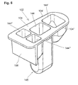
- FIG. 6 Figure 10 shows an alternative embodiment of a system reagent carrier 102 consisting of a plurality of chambers or cuvettes 144, 144 ', 144'',144''.
- a central cuvette 144 is provided which is longer than the further cuvettes 144 ', 144 ", 144''' and which protrudes downward beyond these further cuvettes.
- the central cuvette 144 serves as a measuring cuvette and is intended to be received by a first receiving device 32 of the reaction rotor 12.
- the further cuvettes 144 ', 144 ", 144''' are disposed on two opposite sides of the measuring cuvette 144, the opening of which is adjacent.
- the individual cuvettes 144, 144 ', 144 ", 144''' are interconnected by a frame 104 which simultaneously forms a top surface in which the openings of the cuvettes are formed.
- the frame 104 is substantially trapezoidal in plan view Shape, that is, the two longitudinal sides 104 ', 104 "of the frame 104 at an acute angle to each other. In this way, it is possible to use a plurality of system reagent carriers 102 next to one another in the receiving devices 32 of the reaction rotor 12 in piecemeal fashion.
- the cuvette 144 'located on one side of the measuring cuvette 144 is located radially inside the measuring cuvette 144 with respect to the reaction rotor and arranged on the other side of the measuring cuvette 144 Cuvettes 144 '', 144 '''are located radially outward of the measuring cuvette 144.
- the system reagent carrier 102 On its radially outer side, the system reagent carrier 102 is provided with a substantially vertically extending side panel 106 suitable for mounting the identification code 68 and the manufacturer identification code 70.
- the chambers or cuvettes 144 ', 144 ", 144'” are filled with reagents while the cuvette 144 is empty or may also be filled with a reagent
- the filled system reagent carrier 102 is sealed with a membrane in the manner already described which consists for example of a silicone layer applied to the upper flat surface of the frame 104.
- the measuring cuvette 144 is formed so that it no or only negligibly small measuring resistance counteracts the measuring principle of the detector device 20, so that at least in this area the measuring cuvette 144 is formed a measuring section.
- the invention is not limited to the above embodiments, which are merely for the general explanation of the essence of the invention.
- the inventive device and also accept the described working methods other than the embodiments described above.
- the device may in particular have features that represent a combination of the respective individual features of the claims.
Landscapes
- Chemical & Material Sciences (AREA)
- General Health & Medical Sciences (AREA)
- Immunology (AREA)
- Health & Medical Sciences (AREA)
- Analytical Chemistry (AREA)
- Biochemistry (AREA)
- Physics & Mathematics (AREA)
- General Physics & Mathematics (AREA)
- Life Sciences & Earth Sciences (AREA)
- Pathology (AREA)
- Chemical Kinetics & Catalysis (AREA)
- Automatic Analysis And Handling Materials Therefor (AREA)
- Investigating Or Analysing Biological Materials (AREA)
- General Factory Administration (AREA)
- Editing Of Facsimile Originals (AREA)
Claims (26)
- Système d'analyse, en particulier pour l'analytique médicale pour l'exécution d'analyses cliniques-chimiques et immunologiques, comprenant- un appareil d'analyse (1) et- au moins un support de réactif systémique (2 ; 102),dans lequel l'appareil d'analyse (1) comprend :- au moins un rotor (12) susceptible d'être entraîné en rotation de façon commandée, avec une partie de réception rotative (24) qui est pourvue de premiers dispositifs de réception (32) pour des supports de réactif systémique (2 ; 102) et pour au moins une coupelle de mesure (44 ; 144), de sorte que le rotor (12) forme un rotor de réaction,- un moyen de levage/basculement (18), doté d'un dispositif de pipettage (16), susceptible d'être entraîné de façon commandée et déplaçable le long d'une trajectoire de basculement (36) en direction du rotor (12) et en éloignement de celui-ci,- un moyen détecteur (20),- un moyen de commande (22) pour commander l'entraînement (26) du rotor (12) et l'entraînement (46) du moyen de levage/basculement (18) ainsi que pour la commande du fonctionnement du dispositif de pipettage (16) et du moyen détecteur (20),- dans lequel le moyen détecteur (20) est situé dans la région d'une position angulaire du rotor de réaction telle que l'analyse a lieu dans une coupelle de mesure qui se trouve dans le rotor, et- un dispositif de lecture (64) pour lire un code d'identification (68) lisible à la machine présent sur le support de réactif systémique (2 ; 102) ;- dans lequel le support de réactif systémique (2 ; 102) comprend au moins une coupelle (44', 44" ; 144', 144", 144"') préalablement remplie avec un réactif systémique (45', 45") spécifique au test, préalablement formulé et à effet chimique par voie humide;caractérisé en ce que- il existe une autre partie de réception (14) dans laquelle sont prévus des seconds dispositifs de réception (38) pour des récipients à échantillons (40) à placer sur la trajectoire de basculement (36) du dispositif de pipettage (16), ladite autre partie de réception (14) étant agencée plus haut que la partie de réception rotative (24) ;- l'autre partie de réception (14) est dotée à sa périphérie d'un évidement (42) qui forme pour le dispositif de pipettage (16) un accès vertical vers une coupelle de mesure (44) dans la partie de réception rotative (24) ;- en ce qu'il existe une station de lavage (43) pour le dispositif de pipettage (16);- en ce que le dispositif de lecture (64) est réalisé pour lire et pour évaluer le premier code d'identification (68) lisible à la machine présent sur le support de réactif systémique (2 ; 102), pour des réactifs contenus dans le support de réactif systémique (2 ; 102), et additionnellement un second code d'identification (70) présent sur le support de réactif systémique (2 ; 102) pour l'identification du fabricant du support de réactif systémique (2 ; 102), afin d'identifier le support de réactif systémique (2 ; 102) avec le réactif contenu dans celui-ci, et d'exclure de l'utilisation des supports de réactif systémique inappropriés.
- Système d'analyse selon la revendication 1,
caractérisé en ce que le support de réactif systémique comprend une pluralité de coupelles (44, 44', 44" ; 144, 144', 144", 144"') agencées les unes à côté des autres et reliées les unes aux autres, dans lesquelles au moins une (44', 44" ; 144', 144", 144''') des coupelles (44, 44', 44" ; 144, 144', 144", 144"') est préalablement remplie avec un réactif systémique (45', 45") spécifique au test, formulé préalablement et à effet chimique par voie humide, et d'autres coupelles sont de préférence agencées sur deux côtés opposés d'une coupelle de mesure centrale, lesdits côtés opposés étant de préférence le côté radialement intérieur et le côté radialement extérieur de la coupelle de mesure introduite dans le dispositif de réception, par référence au rayon d'un réacteur de réaction (12). - Système d'analyse selon la revendication 1 ou 2,
caractérisé en ce que le moyen détecteur (20) comprend un détecteur photométrique. - Système d'analyse selon la revendication 1, 2 ou 3,
caractérisé en ce que les seconds dispositifs de réception (38) pour des récipients à échantillons (14) sont formés par des récepteurs stationnaires qui sont agencés sur une trajectoire circulaire (36), laquelle est disposée concentriquement à la trajectoire de basculement du dispositif de levage/basculement (18) qui reçoit le dispositif de pipettage (16). - Système d'analyse selon la revendication 1, 2 ou 3,
caractérisé en ce que les seconds dispositifs de réception (38) pour des récipients à échantillons (40) sont prévus sur un second rotor (86) susceptible d'être entraîné en rotation de façon commandée, lequel est réalisé sous forme d'anneau et agencé concentriquement au rotor de réaction (12) susceptible d'être entraîné en rotation de façon commandée, qui comprend les premiers dispositifs de réception (32) pour des supports de réactif systémique. - Système d'analyse selon l'une des revendications précédentes,
caractérisé en ce que les seconds dispositifs de réception (38) pour des récipients à échantillons (40) et le moyen de commande (22) sont ainsi conçus que des récipients de réactif (41) peuvent être mis en place dans les seconds dispositifs de réception (38). - Système d'analyse selon la revendication 6,
caractérisé en ce qu'il est prévu des récipients de réactif (41) qui sont essentiellement compatibles avec les récipients à échantillons (40), afin de pouvoir être également reçus par les seconds dispositifs de réception (38). - Système d'analyse selon l'une des revendications précédentes,
caractérisé en ce qu'il existe un moyen de lavage (72) pour le nettoyage des coupelles de mesure (44, 44', 44" ; 144). - Système d'analyse selon l'une des revendications précédentes,
caractérisé en ce que l'appareil d'analyse (1) comprend une station de séparation (76) de type "Bound/Free". - Système d'analyse selon la revendication 9,
caractérisé en ce que le moyen détecteur (20) comprend un photomultiplicateur pour des mesures par chimioluminescence. - Système d'analyse selon l'une des revendications précédentes,
caractérisé en ce qu'il est prévu une unité d'évaluation (23) qui évalue les données déterminées par le moyen détecteur (20) en utilisant des données de référence mémorisées dans un moyen formant mémoire (23'). - Système d'analyse selon la revendication 11,
caractérisé en ce qu'il existe un moyen d'affichage (82) pour afficher les résultats fournis par le moyen d'évaluation (23). - Système d'analyse selon la revendication 11 ou 12,
caractérisé en ce qu'il existe un moyen d'impression (84) pour imprimer les résultats fournis par le moyen d'évaluation (23). - Système d'analyse selon l'une des revendications précédentes,
caractérisé en ce que les coupelles (44, 44', 44" ; 144, 144', 144", 144"') sont respectivement fermées avec une membrane (47) susceptible d'être perforée. - Système d'analyse selon l'une des revendications précédentes,
caractérisé en ce que les coupelles (44, 44', 44") d'un support de réactif systémique (2) sont respectivement reliées les unes aux autres via des emplacements de rupture de consigne (45). - Appareil d'analyse, en particulier pour un système d'analyse selon l'une des revendications précédentes, comprenant- au moins un rotor (12) susceptible d'être entraîné en rotation de manière commandée avec une partie de réception rotative (24) qui est doté de premiers dispositifs de réception (32) pour des supports de réactif systémique (2 ; 102) et pour au moins une coupelle de mesure (44 ; 144), de telle façon que le rotor (12) forme un rotor de réaction,- un moyen de levage/basculement (18), doté d'un dispositif de pipettage (16), susceptible d'être entraîné de façon commandée et déplaçable le long d'une trajectoire de basculement (36) en direction du rotor (12) et en éloignement de celui-ci,- un moyen détecteur (20), et- un moyen de commande (22) pour la commande de l'entraînement (26) du rotor (12) et de l'entraînement (46) du moyen de levage/basculement (18) ainsi que pour la commande du fonctionnement du dispositif de pipettage (16) et du moyen détecteur (20),- dans lequel le moyen détecteur (20) est disposé dans la région d'une position angulaire du rotor de réaction telle que l'analyse a lieu dans une coupelle de mesure qui se trouve dans le rotor, et- dans lequel l'appareil d'analyse (1) comprend un dispositif de lecture (64) pour un code d'identification (68) lisible à la machine et présent sur le support de réactif systémique (2 ; 102);caractérisé en ce que- il existe une autre partie de réception (14), dans laquelle sont prévus des seconds dispositifs de réception (38) pour des récipients à échantillons (40) à placer sur la trajectoire de basculement (36) du dispositif de pipettage (16), telle que l'autre partie de réception (14) est agencée plus haut que la partie de réception rotative (24) ;- en ce que l'autre partie de réception (14) est dotée à sa périphérie d'un évidement (42) qui forme pour le dispositif de pipettage (16) un accès vertical vers une coupelle de mesure (44) dans la partie de réception rotative (24) ;- en ce qu'il existe une station de lavage (43) pour le dispositif de pipettage (16) ;- en ce que le dispositif de lecture (64) est réalisé pour lire et pour évaluer le premier code d'identification (68) présent sur le support de réactif systémique (2 ; 102) pour des réactifs contenus dans le support de réactif systémique (2 ; 102) et additionnellement un second code d'identification (70) présent sur le support de réactif systémique (2 ; 102), pour l'identification du fabricant du support de réactif systémique (2 ; 102), afin d'identifier le support de réactif systémique (2 ; 102) avec les réactifs contenus dans celui-ci, et afin d'exclure de l'utilisation des supports de réactif systémique inappropriés.
- Appareil d'analyse selon la revendication 16,
caractérisé en ce que le moyen détecteur (20) comprend un détecteur photométrique. - Appareil d'analyse selon la revendication 16 ou 17,
caractérisé en ce que les seconds dispositifs de réception (38) sont formés par des récepteurs stationnaires qui sont agencés sur une trajectoire circulaire (36), laquelle est disposée concentriquement à la trajectoire de basculement du moyen de levage/basculement (18) qui reçoit le dispositif de pipettage (16). - Appareil d'analyse selon la revendication 16 ou 17,
caractérisé en ce que les seconds dispositifs de réception (38) sont prévus sur un second rotor (86) susceptible d'être entraîné en rotation de façon commandée, qui est réalisé sous forme annulaire et est agencé concentriquement au rotor de réaction (12) susceptible d'être entraîné en rotation de façon commandée, qui comprend les premiers dispositifs de réception (32) pour des supports de réactif systémique. - Appareil d'analyse selon l'une des revendications 16 à 19,
caractérisé en ce que les seconds dispositifs de réception (38) ainsi que le moyen de commande (22) sont réalisés de telle façon que des récipients de réactif (41) peuvent être mis en place dans le second dispositif de réception (38). - Appareil d'analyse selon l'une des revendications 16 à 20,
caractérisé en ce qu'il existe un moyen de lavage (72) pour le nettoyage des coupelles de mesure (44, 44', 44" ; 144). - Appareil d'analyse selon l'une des revendications 16 à 21,
caractérisé en ce que l'appareil d'analyse (1) comprend une station de séparation (76) de type "Bound/Free". - Appareil d'analyse selon la revendication 22,
caractérisé en ce que le moyen détecteur (20) comprend un photomultiplicateur pour une mesure par chimioluminescence. - Appareil d'analyse selon l'une des revendications 16 à 23,
caractérisé en ce qu'il est prévu une unité d'évaluation (23) qui évalue les données déterminées par le moyen détecteur (20) en utilisant des données de référence mémorisées dans un moyen formant mémoire (23'). - Appareil d'analyse selon la revendication 24,
caractérisé en ce qu'il existe un moyen d'affichage (82) pour afficher les résultats fournis par le moyen d'évaluation (23). - Appareil d'analyse selon la revendication 24 ou 25,
caractérisé en ce qu'il existe un moyen d'impression (84) pour imprimer les résultats fournis par le moyen d'évaluation (23).
Priority Applications (1)
| Application Number | Priority Date | Filing Date | Title |
|---|---|---|---|
| EP10010347.2A EP2261675A3 (fr) | 1998-02-20 | 1999-02-19 | Système d'analyse |
Applications Claiming Priority (3)
| Application Number | Priority Date | Filing Date | Title |
|---|---|---|---|
| DE19807177 | 1998-02-20 | ||
| DE19807177A DE19807177A1 (de) | 1998-02-20 | 1998-02-20 | Analysesystem |
| PCT/EP1999/001092 WO1999042841A1 (fr) | 1998-02-20 | 1999-02-19 | Systeme d'analyse |
Related Child Applications (2)
| Application Number | Title | Priority Date | Filing Date |
|---|---|---|---|
| EP10010347.2A Division EP2261675A3 (fr) | 1998-02-20 | 1999-02-19 | Système d'analyse |
| EP10010347.2 Division-Into | 2010-09-23 |
Publications (2)
| Publication Number | Publication Date |
|---|---|
| EP0977996A1 EP0977996A1 (fr) | 2000-02-09 |
| EP0977996B1 true EP0977996B1 (fr) | 2013-05-15 |
Family
ID=7858416
Family Applications (2)
| Application Number | Title | Priority Date | Filing Date |
|---|---|---|---|
| EP99908931.1A Expired - Lifetime EP0977996B1 (fr) | 1998-02-20 | 1999-02-19 | Systeme et appareil d'analyse |
| EP10010347.2A Withdrawn EP2261675A3 (fr) | 1998-02-20 | 1999-02-19 | Système d'analyse |
Family Applications After (1)
| Application Number | Title | Priority Date | Filing Date |
|---|---|---|---|
| EP10010347.2A Withdrawn EP2261675A3 (fr) | 1998-02-20 | 1999-02-19 | Système d'analyse |
Country Status (15)
| Country | Link |
|---|---|
| US (1) | US6375898B1 (fr) |
| EP (2) | EP0977996B1 (fr) |
| JP (1) | JP4081146B2 (fr) |
| KR (2) | KR20010020146A (fr) |
| CN (2) | CN101364276B (fr) |
| AU (1) | AU766654B2 (fr) |
| BR (1) | BR9904832A (fr) |
| CA (1) | CA2287364A1 (fr) |
| DE (2) | DE19807177A1 (fr) |
| HU (1) | HUP0102743A3 (fr) |
| ID (1) | ID23862A (fr) |
| PL (1) | PL336303A1 (fr) |
| TR (1) | TR199902616T1 (fr) |
| TW (2) | TWI234657B (fr) |
| WO (1) | WO1999042841A1 (fr) |
Families Citing this family (62)
| Publication number | Priority date | Publication date | Assignee | Title |
|---|---|---|---|---|
| FR2783321B1 (fr) * | 1998-09-11 | 2000-11-24 | Biotrol Diagnostic | Cuvettes de reaction, ensemble de telles cuvettes, appareil de dosage immunologique et procede mettant en oeuvre de tels ensembles de cuvettes |
| DK1239952T3 (da) * | 1999-12-13 | 2012-01-02 | Illumina Inc | Syntetiseringsindretning til oligonukleotider ved anvendelse af en centrifugalkraft |
| US7390459B2 (en) * | 1999-12-13 | 2008-06-24 | Illumina, Inc. | Oligonucleotide synthesizer |
| DE10006846C2 (de) * | 2000-02-16 | 2002-03-07 | Macherey Nagel Gmbh & Co Hg | Verfahren zur photometrischen CSB-Messung |
| CA2350349A1 (fr) * | 2000-08-30 | 2002-02-28 | Wardlaw Partners Lp | Methode et appareil de controle de la qualite pour les analyses automatisees de matiere biologique |
| US6889468B2 (en) * | 2001-12-28 | 2005-05-10 | 3M Innovative Properties Company | Modular systems and methods for using sample processing devices |
| US7846395B2 (en) * | 2003-07-16 | 2010-12-07 | Ortho-Clinical Diagnostics, Inc. | Container closure and device to install and remove closure |
| US7381370B2 (en) * | 2003-07-18 | 2008-06-03 | Dade Behring Inc. | Automated multi-detector analyzer |
| US8043562B2 (en) * | 2003-12-08 | 2011-10-25 | Ortho-Clinical Diagnostics, Inc. | Analyzer having removable holders or a centrifuge |
| US8211386B2 (en) | 2004-06-08 | 2012-07-03 | Biokit, S.A. | Tapered cuvette and method of collecting magnetic particles |
| US20060159587A1 (en) * | 2005-01-19 | 2006-07-20 | Beckman Coulter, Inc. | Automated clinical analyzer with dual level storage and access |
| US7053373B1 (en) * | 2005-01-19 | 2006-05-30 | Thermo Electron Scientific Instruments Llc | Infrared spectrometer with automated tablet sampling |
| TWI249034B (en) * | 2005-01-21 | 2006-02-11 | Tera Automation Corp Ltd | Storage and injection mechanism of synchronous analysis instrument |
| JP3980031B2 (ja) * | 2005-02-09 | 2007-09-19 | 株式会社日立製作所 | 自動分析装置 |
| USD564667S1 (en) | 2005-07-05 | 2008-03-18 | 3M Innovative Properties Company | Rotatable sample processing disk |
| US7763210B2 (en) * | 2005-07-05 | 2010-07-27 | 3M Innovative Properties Company | Compliant microfluidic sample processing disks |
| US7754474B2 (en) * | 2005-07-05 | 2010-07-13 | 3M Innovative Properties Company | Sample processing device compression systems and methods |
| US7323660B2 (en) * | 2005-07-05 | 2008-01-29 | 3M Innovative Properties Company | Modular sample processing apparatus kits and modules |
| SE529643C3 (sv) * | 2005-07-08 | 2007-11-06 | Hemocue Ab | En kuvett och en metod och ett verktyg för tillverkning därav |
| CN101277758A (zh) * | 2005-09-14 | 2008-10-01 | Illumina公司 | 连续聚合物合成器 |
| US20070098594A1 (en) * | 2005-11-03 | 2007-05-03 | Roche Molecular Systems, Inc. | Analytical multi-spectral optical detection system |
| SE529536C2 (sv) * | 2006-01-25 | 2007-09-04 | Hemocue Ab | Metod för säkerställande av en provbehållares kvalitet |
| JP4525624B2 (ja) * | 2006-03-23 | 2010-08-18 | 日立化成工業株式会社 | 自動分析装置 |
| JP5028186B2 (ja) * | 2007-08-29 | 2012-09-19 | 株式会社日立ハイテクノロジーズ | 自動分析装置 |
| EP2128627B1 (fr) * | 2008-05-30 | 2013-01-09 | F. Hoffmann-La Roche AG | Analyseur pour effectuer une analyse de diagnostic médical |
| JP5534728B2 (ja) | 2009-07-15 | 2014-07-02 | 日東電工株式会社 | 透明フィルムおよびその利用 |
| US8524450B2 (en) * | 2009-10-30 | 2013-09-03 | Illumina, Inc. | Microvessels, microparticles, and methods of manufacturing and using the same |
| USD638550S1 (en) | 2009-11-13 | 2011-05-24 | 3M Innovative Properties Company | Sample processing disk cover |
| USD638951S1 (en) | 2009-11-13 | 2011-05-31 | 3M Innovative Properties Company | Sample processing disk cover |
| USD667561S1 (en) | 2009-11-13 | 2012-09-18 | 3M Innovative Properties Company | Sample processing disk cover |
| US20110117607A1 (en) * | 2009-11-13 | 2011-05-19 | 3M Innovative Properties Company | Annular compression systems and methods for sample processing devices |
| US8834792B2 (en) | 2009-11-13 | 2014-09-16 | 3M Innovative Properties Company | Systems for processing sample processing devices |
| CN202823394U (zh) | 2010-01-19 | 2013-03-27 | 伊鲁米那股份有限公司 | 用于处理化学反应的设备和系统 |
| DE102010008036A1 (de) * | 2010-02-05 | 2011-08-11 | Eppendorf AG, 22339 | Mikrotiterplatte |
| DE102010037009A1 (de) | 2010-08-16 | 2012-02-16 | Drg Instruments Gmbh | Verfahren zur Analyse einer Probe |
| DE102010044283A1 (de) * | 2010-09-03 | 2012-03-08 | M04 Tech Ug (Haftungsbeschränkt) | Vorrichtung und Verfahren zur Analyse biologischer Proben |
| JP2012103097A (ja) * | 2010-11-10 | 2012-05-31 | Tosoh Corp | 試薬キットおよびそれを備えた自動分析装置 |
| CN102043043A (zh) * | 2010-12-10 | 2011-05-04 | 张会生 | 一种多项目生化检验分析集成试剂盒及其方法 |
| BR112013029181B1 (pt) | 2011-05-18 | 2020-11-03 | Focus Diagnostics, Inc. | método e sistema para o processamento de dispositivos de processamento de amostras |
| MX336625B (es) | 2011-05-18 | 2016-01-26 | 3M Innovative Properties Co | Sistemas y metodos para medicion volumetrica en dispositivo de procesamiento de muestra. |
| USD672467S1 (en) | 2011-05-18 | 2012-12-11 | 3M Innovative Properties Company | Rotatable sample processing disk |
| WO2012158988A1 (fr) | 2011-05-18 | 2012-11-22 | 3M Innovative Properties Company | Systèmes et procédés de distribution sur un dispositif de traitement d'échantillons |
| AU2012287300B2 (en) * | 2011-07-22 | 2015-10-01 | Roche Diagnostics Hematology, Inc. | Sample transport systems and methods |
| WO2013060480A2 (fr) * | 2011-10-28 | 2013-05-02 | Torsten Matthias | Dispositif et procédé de contrôle du volume d'un prélèvement |
| USD978375S1 (en) | 2013-03-13 | 2023-02-14 | Abbott Laboratories | Reagent container |
| ES3037815T3 (en) | 2013-03-15 | 2025-10-07 | Abbott Lab | Automated diagnostic analyzers having vertically arranged carousels and related methods |
| JP6165961B2 (ja) | 2013-03-15 | 2017-07-19 | アボット・ラボラトリーズAbbott Laboratories | 前処理カルーセルを有する診断分析装置および関連方法 |
| CN107831324B (zh) | 2013-03-15 | 2021-11-19 | 雅培制药有限公司 | 具有后面可进入轨道系统的自动化诊断分析仪及相关方法 |
| WO2015035324A1 (fr) * | 2013-09-09 | 2015-03-12 | Abbott Laboratories | Systèmes et procédés pour incuber des échantillons |
| CN103558063A (zh) * | 2013-11-21 | 2014-02-05 | 重庆绿色智能技术研究院 | 大气氮素干湿沉降全自动收集装置及样品采集与检测方法 |
| CN103837694B (zh) * | 2014-03-20 | 2015-04-29 | 南通市伊士生物技术有限责任公司 | 全自动两通道定量检测仪 |
| JP5811244B2 (ja) * | 2014-07-18 | 2015-11-11 | 東ソー株式会社 | 試薬キットおよびそれを備えた自動分析装置 |
| CN104181321B (zh) * | 2014-08-20 | 2016-07-20 | 湖南欧杰生物科技发展有限公司 | 多通道自动选择轮流取样分析装置 |
| CN104166006A (zh) * | 2014-08-20 | 2014-11-26 | 长沙新气象自动化技术有限公司 | 一种自动选择轮流分析装置 |
| ES2967313T3 (es) * | 2016-04-21 | 2024-04-29 | Siemens Healthcare Diagnostics Products Gmbh | Procedimiento para la carga optimizada de un dispositivo de recepción con recipientes de líquidos |
| CN106517063A (zh) * | 2017-01-17 | 2017-03-22 | 上海青浦沪西仪器厂 | 一种新型全自动部分收集器 |
| JP6741629B2 (ja) * | 2017-08-10 | 2020-08-19 | 株式会社日立製作所 | 分析装置、分析方法 |
| MX2021012550A (es) * | 2019-04-26 | 2021-11-12 | Hitachi High Tech Corp | Analizador automatico. |
| ES2940487T3 (es) * | 2019-06-06 | 2023-05-08 | Siemens Healthcare Diagnostics Products Gmbh | Dispositivo para el almacenamiento de recipientes para reactivos en varios niveles |
| DE102021126081A1 (de) * | 2021-10-07 | 2023-04-13 | Hach Lange Gmbh | Analysevorbereitungs-Küvettenständereinheit |
| CN116429504B (zh) * | 2023-06-12 | 2023-09-01 | 常州百利锂电智慧工厂有限公司 | 一种全自动取样输送系统 |
| WO2025160618A1 (fr) * | 2024-01-31 | 2025-08-07 | Leica Biosystems Melbourne Pty Ltd | Ensemble pour fluides en vrac refermable |
Citations (3)
| Publication number | Priority date | Publication date | Assignee | Title |
|---|---|---|---|---|
| DE4312093A1 (de) * | 1992-04-13 | 1993-10-14 | Hitachi Ltd | Automatisches Analysensystem |
| US5620898A (en) * | 1993-06-11 | 1997-04-15 | Ortho Diagnostic Systems Inc. | Automated blood analysis system |
| US5698450A (en) * | 1986-10-14 | 1997-12-16 | Ringrose; Anthony | Method for measuring antigens or antibodies in biological fluids |
Family Cites Families (22)
| Publication number | Priority date | Publication date | Assignee | Title |
|---|---|---|---|---|
| US3907505A (en) * | 1973-05-30 | 1975-09-23 | Miles Lab | Selectively detachable apparatus |
| US4046511A (en) * | 1975-06-16 | 1977-09-06 | Union Carbide Corporation | Pipettor apparatus |
| US3994594A (en) * | 1975-08-27 | 1976-11-30 | Technicon Instruments Corporation | Cuvette and method of use |
| CH637766A5 (fr) * | 1977-06-20 | 1983-08-15 | Coulter Electronics | Procede pour controler des reactions chimiques se produisant dans des echantillons de liquides et appareil pour la mise en oeuvre de ce procede. |
| US4265855A (en) * | 1978-11-03 | 1981-05-05 | Electro-Nucleonics, Inc. | System for performing immunochemical and other analyses involving phase separation |
| FI64468C (fi) * | 1982-05-26 | 1983-11-10 | Orion Yhtymae Oy | Analysator |
| DE3405292A1 (de) * | 1984-02-15 | 1985-09-05 | Eppendorf Gerätebau Netheler + Hinz GmbH, 2000 Hamburg | Verfahren zum durchfuehren von probenanalysen sowie rack zur durchfuehrung des verfahrens |
| ATE60446T1 (de) * | 1985-07-15 | 1991-02-15 | Abbott Lab | Reagenzien-behaeltersystem fuer ein klinisches analysegeraet. |
| US4678752A (en) * | 1985-11-18 | 1987-07-07 | Becton, Dickinson And Company | Automatic random access analyzer |
| JP2510152B2 (ja) * | 1985-11-19 | 1996-06-26 | オリンパス光学工業株式会社 | 自動分析装置 |
| US5304786A (en) * | 1990-01-05 | 1994-04-19 | Symbol Technologies, Inc. | High density two-dimensional bar code symbol |
| JP2731229B2 (ja) * | 1989-04-25 | 1998-03-25 | オリンパス光学工業株式会社 | 自動分析装置 |
| JP2881826B2 (ja) * | 1989-07-24 | 1999-04-12 | 東ソー株式会社 | 自動分析装置 |
| GB9020352D0 (en) * | 1990-09-18 | 1990-10-31 | Anagen Ltd | Assay or reaction apparatus |
| TW199858B (fr) * | 1990-03-30 | 1993-02-11 | Fujirebio Kk | |
| ATE134042T1 (de) * | 1991-07-18 | 1996-02-15 | Behring Diagnostics Inc | Vorrichtung fuer den transport von probentraegern in einem automatischen analysegeraet |
| DE4128698A1 (de) * | 1991-08-29 | 1993-03-04 | Boehringer Mannheim Gmbh | Analysesystem |
| EP0746769B1 (fr) * | 1992-03-27 | 2006-09-06 | Abbott Laboratories | Methode d'analyse automatise, a acces continu et aleatoire |
| US5540890A (en) * | 1992-03-27 | 1996-07-30 | Abbott Laboratories | Capped-closure for a container |
| US5270210A (en) * | 1992-07-16 | 1993-12-14 | Schiapparelli Biosystems, Inc. | Capacitive sensing system and wash/alignment station for a chemical analyzer |
| JP3229915B2 (ja) * | 1995-01-19 | 2001-11-19 | 日本電子株式会社 | 生化学自動分析装置 |
| JPH09196925A (ja) * | 1996-01-19 | 1997-07-31 | Hitachi Ltd | 自動分析装置 |
-
1998
- 1998-02-19 ID IDW991195A patent/ID23862A/id unknown
- 1998-02-20 DE DE19807177A patent/DE19807177A1/de not_active Ceased
-
1999
- 1999-02-19 BR BR9904832-9A patent/BR9904832A/pt not_active IP Right Cessation
- 1999-02-19 US US09/403,298 patent/US6375898B1/en not_active Expired - Lifetime
- 1999-02-19 TR TR1999/02616T patent/TR199902616T1/xx unknown
- 1999-02-19 EP EP99908931.1A patent/EP0977996B1/fr not_active Expired - Lifetime
- 1999-02-19 CA CA002287364A patent/CA2287364A1/fr not_active Abandoned
- 1999-02-19 DE DE59912351T patent/DE59912351D1/de not_active Expired - Lifetime
- 1999-02-19 AU AU28351/99A patent/AU766654B2/en not_active Ceased
- 1999-02-19 WO PCT/EP1999/001092 patent/WO1999042841A1/fr not_active Ceased
- 1999-02-19 KR KR1019997009702A patent/KR20010020146A/ko not_active Ceased
- 1999-02-19 KR KR1019997009701A patent/KR20010020145A/ko not_active Ceased
- 1999-02-19 HU HU0102743A patent/HUP0102743A3/hu unknown
- 1999-02-19 PL PL99336303A patent/PL336303A1/xx unknown
- 1999-02-19 JP JP54213299A patent/JP4081146B2/ja not_active Expired - Fee Related
- 1999-02-19 CN CN2008101333444A patent/CN101364276B/zh not_active Expired - Lifetime
- 1999-02-19 CN CN99800595A patent/CN1124489C/zh not_active Expired - Lifetime
- 1999-02-19 EP EP10010347.2A patent/EP2261675A3/fr not_active Withdrawn
- 1999-08-05 TW TW088113506A patent/TWI234657B/zh not_active IP Right Cessation
- 1999-08-05 TW TW088113504A patent/TW521206B/zh not_active IP Right Cessation
Patent Citations (3)
| Publication number | Priority date | Publication date | Assignee | Title |
|---|---|---|---|---|
| US5698450A (en) * | 1986-10-14 | 1997-12-16 | Ringrose; Anthony | Method for measuring antigens or antibodies in biological fluids |
| DE4312093A1 (de) * | 1992-04-13 | 1993-10-14 | Hitachi Ltd | Automatisches Analysensystem |
| US5620898A (en) * | 1993-06-11 | 1997-04-15 | Ortho Diagnostic Systems Inc. | Automated blood analysis system |
Also Published As
| Publication number | Publication date |
|---|---|
| EP2261675A2 (fr) | 2010-12-15 |
| CN1124489C (zh) | 2003-10-15 |
| JP4081146B2 (ja) | 2008-04-23 |
| CN101364276B (zh) | 2013-02-06 |
| AU2835199A (en) | 1999-09-06 |
| HUP0102743A2 (hu) | 2001-11-28 |
| PL336303A1 (en) | 2000-06-19 |
| AU766654B2 (en) | 2003-10-23 |
| TR199902616T1 (xx) | 2000-05-22 |
| CA2287364A1 (fr) | 1999-08-26 |
| TWI234657B (en) | 2005-06-21 |
| WO1999042841A1 (fr) | 1999-08-26 |
| DE59912351D1 (de) | 2005-09-08 |
| KR20010020146A (ko) | 2001-03-15 |
| DE19807177A1 (de) | 1999-09-16 |
| US6375898B1 (en) | 2002-04-23 |
| KR20010020145A (ko) | 2001-03-15 |
| CN1266489A (zh) | 2000-09-13 |
| EP2261675A3 (fr) | 2014-04-16 |
| BR9904832A (pt) | 2000-05-23 |
| CN101364276A (zh) | 2009-02-11 |
| JP2002503346A (ja) | 2002-01-29 |
| ID23862A (id) | 2000-05-25 |
| TW521206B (en) | 2003-02-21 |
| HUP0102743A3 (en) | 2002-02-28 |
| EP0977996A1 (fr) | 2000-02-09 |
Similar Documents
| Publication | Publication Date | Title |
|---|---|---|
| EP2261675A2 (fr) | Système d'analyse | |
| DE69429889T2 (de) | Automatische Blutanalysesystem | |
| DE69834983T2 (de) | Automatisches Blutanalysesystem | |
| DE60218787T2 (de) | Klinische Analysevorrichtung mit keine Waschvorgänge erfordernder Reagenzabgabevorrichtung | |
| DE60220937T2 (de) | Artikelausgabevorrichtung und -verfahren | |
| AT502693B1 (de) | Mischbehälter für eine photometrische messeinrichtung, sowie photometrisches messverfahren für eine probenflüssigkeit | |
| DE602004012187T2 (de) | Automatischer Analysator | |
| DE69220714T2 (de) | Automatischer Analysenapparat, geeignet zum Lesen von Behälterdaten, und Verfahren zur Handhabung von darin verwendeten Reagenzien | |
| DE69429840T2 (de) | Transportsystem für ein Analysengerät für Flüssigkeiten | |
| DE69214013T2 (de) | Reagenzienpackung für Immunoassays | |
| DE60207499T2 (de) | Übertrageeinheit sowie diese beinhaltende automatische Analysevorrichtung | |
| DE3883079T2 (de) | Probenkreis für klinisches Analysatorennetz. | |
| DE10013242B4 (de) | Chemisches Analysegerät | |
| DE3014250A1 (de) | Automatisches analysiergeraet fuer fluessigproben | |
| DE60224757T2 (de) | Zusatz-Zuführsystem für Proben in einem klinischen Analysegerät | |
| DE3014201A1 (de) | Automatisches analysiergeraet fuer fluessigproben | |
| DE19701505A1 (de) | Vorrichtung zum Analysieren einer Vielzahl von Analysesubstanzen | |
| DE4326342A1 (de) | Verfahren zur Analyse von Probenflüssigkeiten | |
| EP3216517B1 (fr) | Procede de melange d'un liquide dans un appareil d'analyse automatique | |
| EP2502082B1 (fr) | Système d'analyse et procédé d'analyse | |
| DE69515565T2 (de) | Analysevorrichtung | |
| DE4231172A1 (de) | Automatisches analysegeraet fuer klinische untersuchungen | |
| EP2482980B1 (fr) | Système d'analyse de liquides | |
| EP3418749B1 (fr) | Surveillance optique de processus de mélange | |
| DE29809188U1 (de) | Analysesystem |
Legal Events
| Date | Code | Title | Description |
|---|---|---|---|
| PUAI | Public reference made under article 153(3) epc to a published international application that has entered the european phase |
Free format text: ORIGINAL CODE: 0009012 |
|
| 17P | Request for examination filed |
Effective date: 19991105 |
|
| AK | Designated contracting states |
Kind code of ref document: A1 Designated state(s): AT CH DE ES FR GB IT LI NL |
|
| RAP1 | Party data changed (applicant data changed or rights of an application transferred) |
Owner name: START DIAGNOSTICS GMBH |
|
| RAP1 | Party data changed (applicant data changed or rights of an application transferred) |
Owner name: START DIAGNOSTICS AG |
|
| RAP1 | Party data changed (applicant data changed or rights of an application transferred) |
Owner name: KABUSHIKI KAISHA HITACHI SEISAKUSHO(HITACHI, LTD.) |
|
| 17Q | First examination report despatched |
Effective date: 20050131 |
|
| REG | Reference to a national code |
Ref country code: HK Ref legal event code: WD Ref document number: 1025632 Country of ref document: HK |
|
| GRAC | Information related to communication of intention to grant a patent modified |
Free format text: ORIGINAL CODE: EPIDOSCIGR1 |
|
| GRAP | Despatch of communication of intention to grant a patent |
Free format text: ORIGINAL CODE: EPIDOSNIGR1 |
|
| GRAS | Grant fee paid |
Free format text: ORIGINAL CODE: EPIDOSNIGR3 |
|
| GRAA | (expected) grant |
Free format text: ORIGINAL CODE: 0009210 |
|
| RAP1 | Party data changed (applicant data changed or rights of an application transferred) |
Owner name: HITACHI CHEMICAL COMPANY, LTD. |
|
| AK | Designated contracting states |
Kind code of ref document: B1 Designated state(s): AT CH DE ES FR GB IT LI NL |
|
| REG | Reference to a national code |
Ref country code: GB Ref legal event code: FG4D Free format text: NOT ENGLISH Ref country code: CH Ref legal event code: EP |
|
| REG | Reference to a national code |
Ref country code: AT Ref legal event code: REF Ref document number: 612409 Country of ref document: AT Kind code of ref document: T Effective date: 20130615 |
|
| REG | Reference to a national code |
Ref country code: DE Ref legal event code: R096 Ref document number: 59915378 Country of ref document: DE Effective date: 20130704 |
|
| REG | Reference to a national code |
Ref country code: CH Ref legal event code: NV Representative=s name: R. A. EGLI AND CO. PATENTANWAELTE, CH |
|
| REG | Reference to a national code |
Ref country code: NL Ref legal event code: VDEP Effective date: 20130515 |
|
| PG25 | Lapsed in a contracting state [announced via postgrant information from national office to epo] |
Ref country code: ES Free format text: LAPSE BECAUSE OF FAILURE TO SUBMIT A TRANSLATION OF THE DESCRIPTION OR TO PAY THE FEE WITHIN THE PRESCRIBED TIME-LIMIT Effective date: 20130826 |
|
| PG25 | Lapsed in a contracting state [announced via postgrant information from national office to epo] |
Ref country code: NL Free format text: LAPSE BECAUSE OF FAILURE TO SUBMIT A TRANSLATION OF THE DESCRIPTION OR TO PAY THE FEE WITHIN THE PRESCRIBED TIME-LIMIT Effective date: 20130515 |
|
| PLBE | No opposition filed within time limit |
Free format text: ORIGINAL CODE: 0009261 |
|
| STAA | Information on the status of an ep patent application or granted ep patent |
Free format text: STATUS: NO OPPOSITION FILED WITHIN TIME LIMIT |
|
| 26N | No opposition filed |
Effective date: 20140218 |
|
| REG | Reference to a national code |
Ref country code: DE Ref legal event code: R097 Ref document number: 59915378 Country of ref document: DE Effective date: 20140218 |
|
| REG | Reference to a national code |
Ref country code: FR Ref legal event code: PLFP Year of fee payment: 17 |
|
| REG | Reference to a national code |
Ref country code: FR Ref legal event code: PLFP Year of fee payment: 18 |
|
| REG | Reference to a national code |
Ref country code: FR Ref legal event code: PLFP Year of fee payment: 19 |
|
| REG | Reference to a national code |
Ref country code: FR Ref legal event code: PLFP Year of fee payment: 20 |
|
| PGFP | Annual fee paid to national office [announced via postgrant information from national office to epo] |
Ref country code: CH Payment date: 20180216 Year of fee payment: 20 Ref country code: GB Payment date: 20180216 Year of fee payment: 20 Ref country code: DE Payment date: 20180219 Year of fee payment: 20 |
|
| PGFP | Annual fee paid to national office [announced via postgrant information from national office to epo] |
Ref country code: IT Payment date: 20180227 Year of fee payment: 20 Ref country code: AT Payment date: 20180219 Year of fee payment: 20 Ref country code: FR Payment date: 20180222 Year of fee payment: 20 |
|
| REG | Reference to a national code |
Ref country code: DE Ref legal event code: R071 Ref document number: 59915378 Country of ref document: DE |
|
| REG | Reference to a national code |
Ref country code: CH Ref legal event code: PL |
|
| REG | Reference to a national code |
Ref country code: GB Ref legal event code: PE20 Expiry date: 20190218 |
|
| REG | Reference to a national code |
Ref country code: AT Ref legal event code: MK07 Ref document number: 612409 Country of ref document: AT Kind code of ref document: T Effective date: 20190219 |
|
| PG25 | Lapsed in a contracting state [announced via postgrant information from national office to epo] |
Ref country code: GB Free format text: LAPSE BECAUSE OF EXPIRATION OF PROTECTION Effective date: 20190218 |