EP0978577A1 - Procédé et dispositif d'usinage électrochimique de pièces - Google Patents
Procédé et dispositif d'usinage électrochimique de pièces Download PDFInfo
- Publication number
- EP0978577A1 EP0978577A1 EP98114849A EP98114849A EP0978577A1 EP 0978577 A1 EP0978577 A1 EP 0978577A1 EP 98114849 A EP98114849 A EP 98114849A EP 98114849 A EP98114849 A EP 98114849A EP 0978577 A1 EP0978577 A1 EP 0978577A1
- Authority
- EP
- European Patent Office
- Prior art keywords
- workpiece
- electrolyte
- tool
- working gap
- gap
- Prior art date
- Legal status (The legal status is an assumption and is not a legal conclusion. Google has not performed a legal analysis and makes no representation as to the accuracy of the status listed.)
- Granted
Links
- 238000000034 method Methods 0.000 title claims abstract description 11
- 238000003754 machining Methods 0.000 title claims description 5
- 239000003792 electrolyte Substances 0.000 claims abstract description 42
- 238000005498 polishing Methods 0.000 claims abstract description 16
- 230000004888 barrier function Effects 0.000 claims abstract description 8
- 239000002184 metal Substances 0.000 claims abstract description 7
- 239000012530 fluid Substances 0.000 claims description 27
- 239000007788 liquid Substances 0.000 claims description 8
- 238000002845 discoloration Methods 0.000 description 7
- 239000000565 sealant Substances 0.000 description 6
- 230000000694 effects Effects 0.000 description 3
- 238000007517 polishing process Methods 0.000 description 3
- 230000007423 decrease Effects 0.000 description 2
- 238000005530 etching Methods 0.000 description 2
- 230000035515 penetration Effects 0.000 description 2
- 238000009736 wetting Methods 0.000 description 2
- 230000015572 biosynthetic process Effects 0.000 description 1
- 230000006835 compression Effects 0.000 description 1
- 238000007906 compression Methods 0.000 description 1
- 238000011161 development Methods 0.000 description 1
- 230000018109 developmental process Effects 0.000 description 1
- 239000007789 gas Substances 0.000 description 1
- XLYOFNOQVPJJNP-UHFFFAOYSA-M hydroxide Chemical compound [OH-] XLYOFNOQVPJJNP-UHFFFAOYSA-M 0.000 description 1
- 239000012535 impurity Substances 0.000 description 1
- 239000011261 inert gas Substances 0.000 description 1
- 239000000463 material Substances 0.000 description 1
- 230000002093 peripheral effect Effects 0.000 description 1
Images

Classifications
-
- B—PERFORMING OPERATIONS; TRANSPORTING
- B23—MACHINE TOOLS; METAL-WORKING NOT OTHERWISE PROVIDED FOR
- B23H—WORKING OF METAL BY THE ACTION OF A HIGH CONCENTRATION OF ELECTRIC CURRENT ON A WORKPIECE USING AN ELECTRODE WHICH TAKES THE PLACE OF A TOOL; SUCH WORKING COMBINED WITH OTHER FORMS OF WORKING OF METAL
- B23H3/00—Electrochemical machining, i.e. removing metal by passing current between an electrode and a workpiece in the presence of an electrolyte
-
- B—PERFORMING OPERATIONS; TRANSPORTING
- B23—MACHINE TOOLS; METAL-WORKING NOT OTHERWISE PROVIDED FOR
- B23H—WORKING OF METAL BY THE ACTION OF A HIGH CONCENTRATION OF ELECTRIC CURRENT ON A WORKPIECE USING AN ELECTRODE WHICH TAKES THE PLACE OF A TOOL; SUCH WORKING COMBINED WITH OTHER FORMS OF WORKING OF METAL
- B23H3/00—Electrochemical machining, i.e. removing metal by passing current between an electrode and a workpiece in the presence of an electrolyte
- B23H3/10—Supply or regeneration of working media
-
- C—CHEMISTRY; METALLURGY
- C25—ELECTROLYTIC OR ELECTROPHORETIC PROCESSES; APPARATUS THEREFOR
- C25F—PROCESSES FOR THE ELECTROLYTIC REMOVAL OF MATERIALS FROM OBJECTS; APPARATUS THEREFOR
- C25F7/00—Constructional parts, or assemblies thereof, of cells for electrolytic removal of material from objects; Servicing or operating
-
- H—ELECTRICITY
- H05—ELECTRIC TECHNIQUES NOT OTHERWISE PROVIDED FOR
- H05K—PRINTED CIRCUITS; CASINGS OR CONSTRUCTIONAL DETAILS OF ELECTRIC APPARATUS; MANUFACTURE OF ASSEMBLAGES OF ELECTRICAL COMPONENTS
- H05K3/00—Apparatus or processes for manufacturing printed circuits
- H05K3/02—Apparatus or processes for manufacturing printed circuits in which the conductive material is applied to the surface of the insulating support and is thereafter removed from such areas of the surface which are not intended for current conducting or shielding
- H05K3/06—Apparatus or processes for manufacturing printed circuits in which the conductive material is applied to the surface of the insulating support and is thereafter removed from such areas of the surface which are not intended for current conducting or shielding the conductive material being removed chemically or electrolytically, e.g. by photo-etch process
- H05K3/07—Apparatus or processes for manufacturing printed circuits in which the conductive material is applied to the surface of the insulating support and is thereafter removed from such areas of the surface which are not intended for current conducting or shielding the conductive material being removed chemically or electrolytically, e.g. by photo-etch process being removed electrolytically
Definitions
- the invention relates to a method for electrochemical machining, in particular Polishing a workpiece having a metal surface, in which the workpiece forms an anode and a tool comprises the cathode, the workpiece relative to the Tool moves continuously and between tool and workpiece Electrolyte current is carried, which hits the workpiece in a first area and on at least a second area is led away from the workpiece via the tool, being in the areas of the workpiece surface wetted by the electrolyte current the electrochemical processing takes place.
- the cathode is formed on both sides to form a Flow chamber surrounded by a wall of the tool.
- the electrolyte flows on one side of the cathode in the working gap and leaves this on the other Side of the cathode. Wear the running gaps on both sides of the working gap no sealants, so there is no local limitation of the processing zone is available.
- a device is known from EP 0 520 324 A1, which, although not for electrochemical processing but is used for etching printed circuit boards. With this one the etching liquid in a delimited chamber, approximately in the middle of the circuit board brought and sucked off on both sides of it.
- the running columns are Sealant assigned in the form of brushes or rollers.
- the surface of the workpiece is removed, and impurities pressed into the surface are also removed. Hydroxide deposits during the polishing process can cause discoloration depending on the current density. This discoloration is caused by lower current densities below approx. 0.5 A / mm 2 (depending on the material composition) and low electrolyte flow rates.
- the current density is highest where the cathode faces the anodic workpiece and depends on the distance. The polishing effect is greatest at these points. As the distance from the cathode increases, the current density decreases exponentially and the polishing effect significantly. Discoloration occurs, which gradually disappears as the distance from the cathode increases or the current density decreases.
- the object of the invention is to provide a method and an apparatus which continuous machining of the surface of a workpiece with any geometry enable and at the same time the formation of discoloration on the Workpiece surface is largely prevented.
- this object is achieved by that in one of the areas by means of a foreign fluid, a barrier to the electrolyte flow is built up, which has a defined tear-off edge of the electrolyte flow on the surface of the workpiece.
- a vacuum can of course also be used be provided, which then with the corresponding pressure of the electrolyte flow corresponds.
- the invention further relates to a device for electrochemical processing, in particular polishing a workpiece having a metal surface, the one Anode forms with a tool having a cathode, with between Workpiece and tool a working gap is formed and the tool one in Has working gap opening supply line and a discharge line for electrolyte liquid and wherein a wall is provided adjacent to the cathode which is in contact with the Workpiece forms a running gap that adjoins the working gap.
- This device is characterized in that in the running gap of the wall Channel opens, which is connected to a supply of an external fluid, the pressure is adjustable with regard to the pressure of the electrolyte flow in the working gap.
- Developments of the invention consist in that on the working gap facing away from the barrel gap connects a closed chamber that over at least the largest part of the processing width or the processing scope of the Workpiece extends, and that the chamber contains the foreign fluid.
- Execution forms a bottom wall of the chamber with the workpiece Barrel gap extension, the sealant at the end facing away from the working gap compared to the workpiece.
- These sealants can, as such known to consist of brush strips or rotatable rollers. This will Leakage losses of the external fluid are kept low. It goes without saying that the Pressostatic supply of foreign fluid is kept at a constant value.
- a gaseous medium such as air or an inert gas, is preferably used as the foreign fluid used, although in special cases it can be advantageous instead of Gases to use a liquid, especially viscous medium, which either does not connect to the electrolyte liquid or easily separates from it leaves.
- Metal surface has a central cathode 14, one with the negative pole DC voltage source is connected.
- the positive pole is connected to the workpiece 10.
- a feed line 16 for Electrolyte fluid In the interior of the cylindrical cathode 14 there is a feed line 16 for Electrolyte fluid.
- a feed line 16 for Electrolyte fluid are located on both sides at a distance from the cathode 14 Walls 18 made of plastic, for example. Between cathode 14 and wall 18 derivatives 20 are formed for the electrolyte.
- the tool 12 with cathode 14 and walls 18 can be circular cylindrical, but also be formed with a rectangular cross-section so that its longitudinal extent runs perpendicular to the paper plane.
- the workpiece 10 moves in the direction of arrow 22 from left to right.
- the cathode 14 is at a certain distance from the workpiece 10. Because of this distance a working gap 24 is formed. In operation, the electrolyte flows through the under pressure Lead 16 in the working gap 24 and fills this and leaves the working gap through the leads 20.
- the walls 18 of the tool 12 protrude beyond Cathode 14 slightly in the direction of the workpiece 10, although this is not mandatory is. In any case, there is a running gap between each wall 18 and the workpiece 10 26 is formed, which represents a leak for the electrolyte current, which during polishing to the undesirable discoloration of the surface of the workpiece 10 would lead to is to avoid.
- a circular-cylindrical tool 12 it extends around the circular-cylindrical one Wall 18 around a chamber 28 extends in a cuboid workpiece 10 the chamber 28 with its longitudinal direction perpendicular to the plane of the drawing and sits on the with respect to the direction of movement of the workpiece 10 front wall 18. Die rear wall 18 does not require such a chamber 28 if the running gap there can be adequately sealed in other ways.
- a chamber 28 is provided on the outside of each of the two walls 18.
- a fluid under pressure that is supplied via a supply line 30 is added. By means of a pressure sensor and a valve, not shown, a maintain preselected pressure of fluid 32 in chamber 28.
- Chamber 28 has a in the bottom wall 34 over the entire length of the chamber 28th extending channel 36, which opens into the running gap 26. Between the bottom wall 34, the chamber 28 and the workpiece 10, a gap extension 38 is formed, the is closed on the outside by a sealant 40 in the form of a brush strip.
- the electrolyte flow in the working gap 24 is below a certain level Overpressure, for example of 0.5 bar.
- the pressure of the fluid is now in the chamber 28 32 is set to a value which, as a first approximation, corresponds to the pressure in the working gap 24 corresponds, but depending on the shape of the tool 12 also slightly larger or smaller can be.
- the pressure of the fluid 32 is in the chamber 28 set slightly below 0.5 bar, which leads to the electrolyte being slightly in enters the running gap 26, resulting in a slight compression of the fluid, this however forms a barrier 42 against further penetration of the electrolyte.
- a defined one is formed Tear-off edge, so that the polishing process - based on a stationary workpiece 10 - this edge ends. When the workpiece is moved, this tear-off edge moves against the Direction of movement on the workpiece surface to the rear.
- the fluid would slightly enter the working gap 24 and through the lead 20 is drawn off with the electrolyte.
- a gaseous fluid 32 would form 24 bubbles in the electrolyte at the entry into the working gap escape through the derivative 20.
- the barrier 42 would also be built are so that the tear-off edge is only slightly opposite Movement direction of the workpiece 10 shifts.
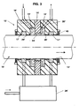
- the tool 12 ' is used for electrochemical polishing circular cylindrical Workpieces 10 '.
- the tool 12 ' has a circular cylindrical passage 13', the Diameter is slightly larger than the outer diameter of the workpiece 10 '.
- a ring cathode 14' which with the Workpiece 10 'forms a working gap 24'.
- Both sides of the cathode 14 ' are in the Tool 12 'annular grooves 15', in one of which a feed line 16 'and in the other one Lead 20 'open.
- each annular groove 15 'facing away from the working gap 24' is located in an axial distance in each case a further annular groove 17 ', which by means of holes on the Chamber 28 'are connected, which contains the supply of fluid.
- a further annular groove 17 ' which by means of holes on the Chamber 28 'are connected, which contains the supply of fluid.
Landscapes
- Engineering & Computer Science (AREA)
- Chemical & Material Sciences (AREA)
- Chemical Kinetics & Catalysis (AREA)
- Electrochemistry (AREA)
- Mechanical Engineering (AREA)
- Manufacturing & Machinery (AREA)
- Microelectronics & Electronic Packaging (AREA)
- Materials Engineering (AREA)
- Metallurgy (AREA)
- Organic Chemistry (AREA)
- Electrical Discharge Machining, Electrochemical Machining, And Combined Machining (AREA)
Priority Applications (3)
| Application Number | Priority Date | Filing Date | Title |
|---|---|---|---|
| DE59810471T DE59810471D1 (de) | 1998-08-07 | 1998-08-07 | Verfahren und Vorrichtung zum elektrochemischen Bearbeiten von Werkstücken |
| EP98114849A EP0978577B1 (fr) | 1998-08-07 | 1998-08-07 | Procédé et dispositif d'usinage électrochimique de pièces |
| US09/166,006 US6099715A (en) | 1998-08-07 | 1998-10-05 | Method for electrochemical treatment, especially for polishing |
Applications Claiming Priority (1)
| Application Number | Priority Date | Filing Date | Title |
|---|---|---|---|
| EP98114849A EP0978577B1 (fr) | 1998-08-07 | 1998-08-07 | Procédé et dispositif d'usinage électrochimique de pièces |
Publications (2)
| Publication Number | Publication Date |
|---|---|
| EP0978577A1 true EP0978577A1 (fr) | 2000-02-09 |
| EP0978577B1 EP0978577B1 (fr) | 2003-12-17 |
Family
ID=8232418
Family Applications (1)
| Application Number | Title | Priority Date | Filing Date |
|---|---|---|---|
| EP98114849A Expired - Lifetime EP0978577B1 (fr) | 1998-08-07 | 1998-08-07 | Procédé et dispositif d'usinage électrochimique de pièces |
Country Status (3)
| Country | Link |
|---|---|
| US (1) | US6099715A (fr) |
| EP (1) | EP0978577B1 (fr) |
| DE (1) | DE59810471D1 (fr) |
Cited By (3)
| Publication number | Priority date | Publication date | Assignee | Title |
|---|---|---|---|---|
| DE10028675A1 (de) * | 1999-11-25 | 2001-05-31 | Frembgen Fritz Herbert | Verfahren zur Bearbeitung von Werkstücken |
| US7803258B2 (en) | 1999-11-04 | 2010-09-28 | Edk Research Ag | Machine for localized cleaning with an electrolytic cell, for pickling and/or polishing metal surfaces |
| DE102023101632A1 (de) * | 2023-01-24 | 2024-07-25 | Zf Active Safety Gmbh | Fluidseparation für ein Eloxal-Verfahren |
Families Citing this family (4)
| Publication number | Priority date | Publication date | Assignee | Title |
|---|---|---|---|---|
| US7192260B2 (en) * | 2003-10-09 | 2007-03-20 | Lehr Precision, Inc. | Progressive cavity pump/motor stator, and apparatus and method to manufacture same by electrochemical machining |
| KR100587657B1 (ko) * | 2003-12-31 | 2006-06-08 | 동부일렉트로닉스 주식회사 | 이씨피공정에서의 터미날 효과 최소화 방법 |
| US9976227B2 (en) | 2014-05-15 | 2018-05-22 | Baker Hughes, A Ge Company, Llc | Electrochemical machining method for rotors or stators for moineau pumps |
| DE102018203988B4 (de) * | 2018-03-15 | 2024-03-21 | Airbus Defence and Space GmbH | Werkzeugkopf zur lokalen nasschemischen Oberflächenbehandlung und Vorrichtung zur lokalen nasschemischen Behandlung, insbesondere Anodisierung |
Citations (4)
| Publication number | Priority date | Publication date | Assignee | Title |
|---|---|---|---|---|
| DE1931174A1 (de) * | 1969-06-19 | 1971-01-07 | Siemens Ag | Einrichtung zum elektrolytischen Polieren von Kernbrennstabhuellrohren |
| GB1465431A (en) * | 1976-01-09 | 1977-02-23 | Electricity Council | Electrolytic treatment of elongate articles such as bars tubes or strips |
| GB2203756A (en) * | 1987-04-14 | 1988-10-26 | Atomic Energy Authority Uk | Electrolytic treatment device |
| WO1993014249A1 (fr) * | 1992-01-10 | 1993-07-22 | Ian Leonard | Procedes et appareils d'usinage electrochimique |
Family Cites Families (7)
| Publication number | Priority date | Publication date | Assignee | Title |
|---|---|---|---|---|
| US3293163A (en) * | 1964-04-10 | 1966-12-20 | Easco Products Inc | Method of maintaining spacing in electric-discharge and electro-chemical machining |
| US3616343A (en) * | 1964-08-08 | 1971-10-26 | Inoue K | Electrochemical machining method |
| US4222834A (en) * | 1979-06-06 | 1980-09-16 | Western Electric Company, Inc. | Selectively treating an article |
| US4486279A (en) * | 1983-05-12 | 1984-12-04 | Westinghouse Electric Corp. | Apparatus and method for making a laminated core |
| DE4121032A1 (de) * | 1991-06-26 | 1993-01-07 | Schmid Gmbh & Co Geb | Vorrichtung zum behandeln von plattenfoermigen gegenstaenden, insbesondere leiterplatten |
| US5378331A (en) * | 1993-05-04 | 1995-01-03 | Kemp Development Corporation | Apparatus and method for electropolishing metal workpieces |
| FR2714080B1 (fr) * | 1993-12-16 | 1996-03-01 | Dalic | Dispositif pour le traitement électrochimique, notamment localisé, d'un substrat conducteur. |
-
1998
- 1998-08-07 DE DE59810471T patent/DE59810471D1/de not_active Expired - Fee Related
- 1998-08-07 EP EP98114849A patent/EP0978577B1/fr not_active Expired - Lifetime
- 1998-10-05 US US09/166,006 patent/US6099715A/en not_active Expired - Fee Related
Patent Citations (4)
| Publication number | Priority date | Publication date | Assignee | Title |
|---|---|---|---|---|
| DE1931174A1 (de) * | 1969-06-19 | 1971-01-07 | Siemens Ag | Einrichtung zum elektrolytischen Polieren von Kernbrennstabhuellrohren |
| GB1465431A (en) * | 1976-01-09 | 1977-02-23 | Electricity Council | Electrolytic treatment of elongate articles such as bars tubes or strips |
| GB2203756A (en) * | 1987-04-14 | 1988-10-26 | Atomic Energy Authority Uk | Electrolytic treatment device |
| WO1993014249A1 (fr) * | 1992-01-10 | 1993-07-22 | Ian Leonard | Procedes et appareils d'usinage electrochimique |
Cited By (3)
| Publication number | Priority date | Publication date | Assignee | Title |
|---|---|---|---|---|
| US7803258B2 (en) | 1999-11-04 | 2010-09-28 | Edk Research Ag | Machine for localized cleaning with an electrolytic cell, for pickling and/or polishing metal surfaces |
| DE10028675A1 (de) * | 1999-11-25 | 2001-05-31 | Frembgen Fritz Herbert | Verfahren zur Bearbeitung von Werkstücken |
| DE102023101632A1 (de) * | 2023-01-24 | 2024-07-25 | Zf Active Safety Gmbh | Fluidseparation für ein Eloxal-Verfahren |
Also Published As
| Publication number | Publication date |
|---|---|
| EP0978577B1 (fr) | 2003-12-17 |
| US6099715A (en) | 2000-08-08 |
| DE59810471D1 (de) | 2004-01-29 |
Similar Documents
| Publication | Publication Date | Title |
|---|---|---|
| DE3001726C2 (de) | Vorrichtung zum Behandeln einer Leiterplatte | |
| DE3643036A1 (de) | Halterung fuer elektroden in der analytischen chemie | |
| EP0026401A1 (fr) | Dispositif pour exercer une pression sur la surface de pièces à travailler en mouvement | |
| DE112019003791T5 (de) | Fluiddruckgetriebene drucknietvorrichtung | |
| DE4402596C2 (de) | Elektrolytisches Verfahren in horizontalen Durchlaufanlagen und Vorrichtung zur Durchführung desselben | |
| DE4019662C2 (de) | Maschine zum funkenerosiven Schneiden mit einem die Rückwand des Arbeitsflüssigkeits-Behälters durchquerenden Führungsarm | |
| DE68905314T2 (de) | Saugnapf zur elektrolytischen behandlung einer oberflaeche. | |
| DE3738251A1 (de) | Drahtschneidende elektrische entladungsbearbeitungsvorrichtung | |
| EP0978577B1 (fr) | Procédé et dispositif d'usinage électrochimique de pièces | |
| DE3223623A1 (de) | Zufuehreinrichtung fuer die bearbeitungsfluessigkeit bei elektroerosionsmaschinen mit beweglicher drahtelektrode | |
| DE1552122B1 (de) | Verfahren und vorrichtung zum abtrennen von werkstueck abschnitten durch eine druckfluessigkeit | |
| EP0026396A1 (fr) | Dispositif pour exercer une pression sur la surface de pièces à travailler en mouvement | |
| DE2811427C2 (de) | Elektronenstrahlschweißmaschine | |
| EP1182359B1 (fr) | Actionneur linéaire sans tige et son carter | |
| DE10085445B4 (de) | Drahterodierbearbeitungseinrichtung | |
| DE3241780C2 (de) | Verfahren zum funkenerosiven Senkerodieren | |
| EP0045956A2 (fr) | Dispositif de poinçonnage | |
| DE10222874B4 (de) | Füllanlage zum luftblasenfreien Füllen von in Leiterplatten eingebrachten Löchern mit einem Füllmaterial | |
| DE102022204734A1 (de) | Hydraulischer Schalter und Bohrhammer | |
| DE19728893A1 (de) | Vakuumdichtung für eine Schlittenführung einer mechanischen Presse | |
| DE3340980A1 (de) | Verfahren und vorrichtung zur elektroentladungsbearbeitung mit rueckstandsbeseitigung | |
| CH669349A5 (fr) | ||
| DE102020214344A1 (de) | Werkzeugkathode sowie Verfahren zum Herstellen einer Werkzeugkathode zum elektrochemischen Bearbeiten | |
| DE3230735C2 (de) | Verfahren zur Massenfertigung von Kanülen, Kanüle, Vorrichtung zur Durchführung des Verfahrens und Anwendungen | |
| DE2121110C3 (de) | Vorrichtung zum elektrochemischen Entgraten |
Legal Events
| Date | Code | Title | Description |
|---|---|---|---|
| PUAI | Public reference made under article 153(3) epc to a published international application that has entered the european phase |
Free format text: ORIGINAL CODE: 0009012 |
|
| AK | Designated contracting states |
Kind code of ref document: A1 Designated state(s): DE ES FR GB IT |
|
| AX | Request for extension of the european patent |
Free format text: AL;LT;LV;MK;RO;SI |
|
| 17P | Request for examination filed |
Effective date: 20000712 |
|
| AKX | Designation fees paid |
Free format text: DE ES FR GB IT |
|
| 17Q | First examination report despatched |
Effective date: 20030211 |
|
| GRAH | Despatch of communication of intention to grant a patent |
Free format text: ORIGINAL CODE: EPIDOS IGRA |
|
| GRAS | Grant fee paid |
Free format text: ORIGINAL CODE: EPIDOSNIGR3 |
|
| GRAA | (expected) grant |
Free format text: ORIGINAL CODE: 0009210 |
|
| AK | Designated contracting states |
Kind code of ref document: B1 Designated state(s): DE ES FR GB IT |
|
| PG25 | Lapsed in a contracting state [announced via postgrant information from national office to epo] |
Ref country code: IT Free format text: LAPSE BECAUSE OF FAILURE TO SUBMIT A TRANSLATION OF THE DESCRIPTION OR TO PAY THE FEE WITHIN THE PRE;WARNING: LAPSES OF ITALIAN PATENTS WITH EFFECTIVE DATE BEFORE 2007 MAY HAVE OCCURRED AT ANY TIME BEFORE 2007. THE CORRECT EFFECTIVE DATE MAY BE DIFFERENT FROM THE ONE RECORDED.SCRIBED TIME-LIMIT Effective date: 20031217 Ref country code: GB Free format text: LAPSE BECAUSE OF FAILURE TO SUBMIT A TRANSLATION OF THE DESCRIPTION OR TO PAY THE FEE WITHIN THE PRESCRIBED TIME-LIMIT Effective date: 20031217 Ref country code: ES Free format text: LAPSE BECAUSE OF FAILURE TO SUBMIT A TRANSLATION OF THE DESCRIPTION OR TO PAY THE FEE WITHIN THE PRESCRIBED TIME-LIMIT Effective date: 20031217 |
|
| REG | Reference to a national code |
Ref country code: GB Ref legal event code: FG4D Free format text: NOT ENGLISH |
|
| REF | Corresponds to: |
Ref document number: 59810471 Country of ref document: DE Date of ref document: 20040129 Kind code of ref document: P |
|
| GBV | Gb: ep patent (uk) treated as always having been void in accordance with gb section 77(7)/1977 [no translation filed] |
Effective date: 20031217 |
|
| ET | Fr: translation filed | ||
| PLBE | No opposition filed within time limit |
Free format text: ORIGINAL CODE: 0009261 |
|
| STAA | Information on the status of an ep patent application or granted ep patent |
Free format text: STATUS: NO OPPOSITION FILED WITHIN TIME LIMIT |
|
| 26N | No opposition filed |
Effective date: 20040920 |
|
| PGFP | Annual fee paid to national office [announced via postgrant information from national office to epo] |
Ref country code: FR Payment date: 20080818 Year of fee payment: 11 |
|
| PGFP | Annual fee paid to national office [announced via postgrant information from national office to epo] |
Ref country code: DE Payment date: 20081014 Year of fee payment: 11 |
|
| REG | Reference to a national code |
Ref country code: FR Ref legal event code: ST Effective date: 20100430 |
|
| PG25 | Lapsed in a contracting state [announced via postgrant information from national office to epo] |
Ref country code: FR Free format text: LAPSE BECAUSE OF NON-PAYMENT OF DUE FEES Effective date: 20090831 Ref country code: DE Free format text: LAPSE BECAUSE OF NON-PAYMENT OF DUE FEES Effective date: 20100302 |