EP0978661A2 - Accouplement par friction - Google Patents
Accouplement par friction Download PDFInfo
- Publication number
- EP0978661A2 EP0978661A2 EP99113614A EP99113614A EP0978661A2 EP 0978661 A2 EP0978661 A2 EP 0978661A2 EP 99113614 A EP99113614 A EP 99113614A EP 99113614 A EP99113614 A EP 99113614A EP 0978661 A2 EP0978661 A2 EP 0978661A2
- Authority
- EP
- European Patent Office
- Prior art keywords
- force
- parts
- positive
- connection
- locking element
- Prior art date
- Legal status (The legal status is an assumption and is not a legal conclusion. Google has not performed a legal analysis and makes no representation as to the accuracy of the status listed.)
- Ceased
Links
- 239000011324 bead Substances 0.000 claims description 8
- 239000000463 material Substances 0.000 claims description 5
- 238000007493 shaping process Methods 0.000 claims 1
- 239000011343 solid material Substances 0.000 claims 1
- 238000010276 construction Methods 0.000 description 2
- 238000004519 manufacturing process Methods 0.000 description 2
- 229910000831 Steel Inorganic materials 0.000 description 1
- 238000006073 displacement reaction Methods 0.000 description 1
- 238000000034 method Methods 0.000 description 1
- 239000010959 steel Substances 0.000 description 1
Images
Classifications
-
- F—MECHANICAL ENGINEERING; LIGHTING; HEATING; WEAPONS; BLASTING
- F16—ENGINEERING ELEMENTS AND UNITS; GENERAL MEASURES FOR PRODUCING AND MAINTAINING EFFECTIVE FUNCTIONING OF MACHINES OR INSTALLATIONS; THERMAL INSULATION IN GENERAL
- F16B—DEVICES FOR FASTENING OR SECURING CONSTRUCTIONAL ELEMENTS OR MACHINE PARTS TOGETHER, e.g. NAILS, BOLTS, CIRCLIPS, CLAMPS, CLIPS OR WEDGES; JOINTS OR JOINTING
- F16B5/00—Joining sheets or plates, e.g. panels, to one another or to strips or bars parallel to them
- F16B5/07—Joining sheets or plates, e.g. panels, to one another or to strips or bars parallel to them by means of multiple interengaging protrusions on the surfaces, e.g. hooks, coils
Definitions
- the invention relates to a frictional connection, in particular for joining two elongated components according to the Oberbgeriff of claim 1, preferably for the Automotive engineering.
- connection points such as sills, fenders or door panels, that need to be connected to other vehicle components.
- the frictional connection according to the invention for two parts to be connected with each other mutually facing connection surfaces and with at least one between them pressable force-locking element with part-side pressure surfaces is that the Force-locking element several pressure elements formed one behind the other at a distance has forming wedge-shaped flanks with which it counteracts with them Projections is pressed, either on at least one of the parts to be connected or formed on a second force-locking element pushed between the parts are.
- two components with elongated straight can Connecting surfaces, for example a sill or a fender and a side panel a motor vehicle.
- the frictional connection element can be in operative connection with a clamping screw causes the feed and the frictional element with its wedge-shaped flanks against pulls the protrusions of one part and thereby the one for a stable connection required contact pressure and thus generates the adhesion.
- a clamping screw causes the feed and the frictional element with its wedge-shaped flanks against pulls the protrusions of one part and thereby the one for a stable connection required contact pressure and thus generates the adhesion.
- a permanent Non-positive connection it is necessary that the non-positive element in its joining or The non-positive position is fixed.
- the active connection with a clamping screw it can be in its feed direction Front or face a flange or a differently designed bearing for the Have clamping screw, the second abutment on the other part or on has another component.
- the force-locking element can be designed in the form of a band, the flanks in the Band material can be molded. With this embodiment, one is by its Design limited elastic force-locking element given by that too Manufacturing tolerance deviations can be recorded and it is ensured that each flank contributes to the adhesion.
- Another embodiment is molded from plastic.
- the flanks are on molded wedges.
- Here are a minimum elasticity to compensate for Manufacturing tolerance deviations due to the material and the required stability for Generation of the contact pressure given by the wedges molded from full material.
- Protrusions formed projections can, if necessary, by beads by wedge-shaped beads, or in the simple case by point-like elevations be educated.
- the non-positive connection is established in that the two non-positive elements with corresponding flanks and projections brought between the parts and be shifted relative to each other.
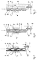
- 1 is a frictional connection according to the invention with two components 1 and 2 shown, which are arranged at a distance from each other and by indicated abutment W supported or, as shown in Fig. 5, by their design at a maximum distance are locked to each other.
- a band-shaped force-locking element 3 made of steel with wedge-shaped flanks 4 and a second force-locking element 5 with wedge-shaped projections 6 made of plastic pushed.
- the force-locking element 3 has a flange-like bend 7 for one Clamping screw 8, which has a fixed abutment 9.
- the force-locking element 5 is on Component 2 locked by a shoulder 10.
- the force-locking element 3 is in the direction of the arrow moved down.
- the flanks 4 come into engagement with the projections 6, and it creates a force component P across the gap, which is used for the frictional connection between the the abutment W supports parts 1 and 2 and the force-locking elements 3 and 5, through which the parts 1 and 2 are non-positively connected.
- Fig. 2 shows the same arrangement in principle, but with a second force-locking element 11, in which the projections are formed by beads 12, which with the flanks 4 of the Force-locking element 3 correspond.
- FIG. 3 shows a frictional connection according to the invention, in which a component 13 is provided with projections formed by beads 14, which with the flanks 4 of the Force-locking element 3 correspond.
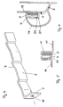
- Fig. 4 shows a frictional engagement element 3 according to the invention in a perspective view.
- a bore 15 is arranged for a clamping screw 8.
- FIG. 5 and 6 arrangements are shown in which two parts 16 and 17 or 18 and 19th are arranged hooked together and thereby have a mutual abutment W.
- the Part 16 in FIG. 5 has point-like projections 20.
- a force-locking element 3 is between the two parts 16 and 17 arranged and leads to a displacement through which Flanks 4 engage with the projections 20 and exert pressure on them, to a frictional connection between parts 16 and 17 and the Force locking element 3.
- FIG. 6 shows the connection of a sill 18 to a side part 19.
- the as Open profile trained sill 18 is with a profile edge with the side part 19th welded (S) and non-positively connected to the other profile edge.
- the frictional connection arrangement corresponds in principle to that shown in FIG. 5, but is to enable an interlocking of the two parts 18 and 19 on an angle profile 21 the side part 19 welded and provided with beads 22. If the Force-locking element 3, the flanged edge of the sill 18 is non-positively with the Force-locking element 3 and the side part 19 connected.
Landscapes
- Engineering & Computer Science (AREA)
- General Engineering & Computer Science (AREA)
- Mechanical Engineering (AREA)
- Clamps And Clips (AREA)
- Mutual Connection Of Rods And Tubes (AREA)
- Connection Of Plates (AREA)
Applications Claiming Priority (2)
| Application Number | Priority Date | Filing Date | Title |
|---|---|---|---|
| DE1998135560 DE19835560A1 (de) | 1998-08-06 | 1998-08-06 | Kraftschluß-Verbindung |
| DE19835560 | 1998-08-06 |
Publications (2)
| Publication Number | Publication Date |
|---|---|
| EP0978661A2 true EP0978661A2 (fr) | 2000-02-09 |
| EP0978661A3 EP0978661A3 (fr) | 2001-04-04 |
Family
ID=7876669
Family Applications (1)
| Application Number | Title | Priority Date | Filing Date |
|---|---|---|---|
| EP99113614A Ceased EP0978661A3 (fr) | 1998-08-06 | 1999-07-12 | Accouplement par friction |
Country Status (2)
| Country | Link |
|---|---|
| EP (1) | EP0978661A3 (fr) |
| DE (1) | DE19835560A1 (fr) |
Cited By (2)
| Publication number | Priority date | Publication date | Assignee | Title |
|---|---|---|---|---|
| WO2000055510A1 (fr) * | 1999-03-17 | 2000-09-21 | Siemens Sgp Verkehrstechnik Gmbh | Support reglable en hauteur situe entre deux plaques paralleles |
| EP3026350A1 (fr) * | 2014-11-26 | 2016-06-01 | Miele & Cie. KG | Composant |
Families Citing this family (1)
| Publication number | Priority date | Publication date | Assignee | Title |
|---|---|---|---|---|
| US8091745B2 (en) | 2004-06-25 | 2012-01-10 | Impress Group B.V. | Disposable tap for a pressurized liquid container |
Family Cites Families (10)
| Publication number | Priority date | Publication date | Assignee | Title |
|---|---|---|---|---|
| GB711324A (en) * | 1952-04-03 | 1954-06-30 | Erwin Backhaus Junior | Improvements in elastic mountings for bolts or shafts |
| DE1845226U (de) * | 1961-08-03 | 1962-01-18 | Bbc Brown Boveri & Cie | Befestigungsvorrichtung. |
| DE1873892U (de) * | 1962-12-22 | 1963-06-12 | Raymond Druckknopf Und Metallw | Zweiteilige befestigungsvorrichtung fuer fensterschachtabdeckungen an fahrzeugen. |
| US3312500A (en) * | 1965-08-02 | 1967-04-04 | Gen Motors Corp | Molding |
| DE8634436U1 (de) * | 1986-12-23 | 1987-02-12 | Vestatec Schwien & Körning GmbH & Co KG, 4620 Castrop-Rauxel | Befestigungsvorrichtung |
| US5242200A (en) * | 1989-09-12 | 1993-09-07 | Artur Kamm | Arrangement of molded parts such as bumpers or their trim in automotive vehicles |
| DE4011237C1 (fr) * | 1990-04-06 | 1991-06-20 | Dr.Ing.H.C. F. Porsche Ag, 7000 Stuttgart, De | |
| FR2683872B1 (fr) * | 1991-11-14 | 1994-02-25 | Sulzer Cie Construction Meca | Dispositif elementaire et systeme global pour le positionnement d'un corps, tel que pompe, par rapport a un autre corps. |
| DE4208308C2 (de) * | 1992-03-16 | 1995-04-20 | Akzo Nobel Faser Ag | Gehäuse zum ballistischen Schutz von Personen und/oder Objekten |
| DE4301975C1 (de) * | 1993-01-26 | 1993-10-07 | Daimler Benz Ag | Blechmutter zur Befestigung eines Losteils an einem Tragteil |
-
1998
- 1998-08-06 DE DE1998135560 patent/DE19835560A1/de not_active Withdrawn
-
1999
- 1999-07-12 EP EP99113614A patent/EP0978661A3/fr not_active Ceased
Cited By (2)
| Publication number | Priority date | Publication date | Assignee | Title |
|---|---|---|---|---|
| WO2000055510A1 (fr) * | 1999-03-17 | 2000-09-21 | Siemens Sgp Verkehrstechnik Gmbh | Support reglable en hauteur situe entre deux plaques paralleles |
| EP3026350A1 (fr) * | 2014-11-26 | 2016-06-01 | Miele & Cie. KG | Composant |
Also Published As
| Publication number | Publication date |
|---|---|
| EP0978661A3 (fr) | 2001-04-04 |
| DE19835560A1 (de) | 2000-02-10 |
Similar Documents
| Publication | Publication Date | Title |
|---|---|---|
| EP0268815B1 (fr) | Dispositif de fixation d'une fenêtre dans la baie de carrosserie d'un véhicule automobile | |
| DE60026487T2 (de) | Einsteckmutter | |
| DE2402952A1 (de) | Verfahren zum verbinden der kanten von platten, beispielsweise metallplatten | |
| DE602005002868T2 (de) | Kraftfahrzeugrahmenanordnung | |
| DE29520573U1 (de) | Zier- oder Stoßleiste für Fahrzeuge | |
| DE4023393A1 (de) | Verbindung und verfahren zur einzelseitenverschweissung und selbstbefestigung geschlossener stahlquerschnitte | |
| EP1516990A1 (fr) | Organe composite, notamment pour une vitre coulissante de véhicule | |
| DE10122637B4 (de) | Dichtungsanordnung für eine Kraftfahrzeugtüre und/oder ein Kraftfahrzeugfenster | |
| EP0441287B1 (fr) | Lame métallique d'insertion pour bandes d'enjolivement et d'étanchéité | |
| DE102009010296A1 (de) | Verbindungsanordnung eines Anbauteils an einem Karosseriebauteil | |
| EP0978661A2 (fr) | Accouplement par friction | |
| DE102013014207A1 (de) | Kraftfahrzeugkarosserie und Montageverfahren dafür | |
| DE102024136366A1 (de) | Airbaghalter mit montageverhinderung und -überprüfung | |
| DE3606812A1 (de) | Verkleidung fuer einen einstiegsschweller eines kraftfahrzeugs | |
| DE102018201493B4 (de) | Verkleidungsteil für ein Kraftfahrzeug und Verwendung | |
| DE102020117183A1 (de) | Bauteilverbund | |
| EP2105065A1 (fr) | Corps de meuble | |
| EP1587195A2 (fr) | Système de canalisation pour câble | |
| DE29902938U1 (de) | Mittels einem Zwischenstück verbundene Zierleisten eines Kraftfahrzeuges | |
| DE102006021457B4 (de) | Metallverstärkter Kunststoffträger für ein Fahrzeug | |
| EP0148484A1 (fr) | Joint de brides | |
| DE2810630A1 (de) | Herstellungsverfahren eines verbundprofils und verbundprofil | |
| DE102004050540A1 (de) | Befestigungsmittel zur Montage eines Verkleidungsteils | |
| EP0610691A1 (fr) | Fenêtre ouvrante de carrosserie pour véhicules à moteur | |
| DE19611687A1 (de) | Adapterprofil zur Verbindung von Rahmenprofilen |
Legal Events
| Date | Code | Title | Description |
|---|---|---|---|
| PUAI | Public reference made under article 153(3) epc to a published international application that has entered the european phase |
Free format text: ORIGINAL CODE: 0009012 |
|
| AK | Designated contracting states |
Kind code of ref document: A2 Designated state(s): AT BE CH CY DE DK ES FI FR GB GR IE IT LI LU MC NL PT SE |
|
| AX | Request for extension of the european patent |
Free format text: AL;LT;LV;MK;RO;SI |
|
| PUAL | Search report despatched |
Free format text: ORIGINAL CODE: 0009013 |
|
| AK | Designated contracting states |
Kind code of ref document: A3 Designated state(s): AT BE CH CY DE DK ES FI FR GB GR IE IT LI LU MC NL PT SE |
|
| AX | Request for extension of the european patent |
Free format text: AL;LT;LV;MK;RO;SI |
|
| 17P | Request for examination filed |
Effective date: 20011004 |
|
| AKX | Designation fees paid |
Free format text: AT BE CH CY DE DK ES FI FR GB GR IE IT LI LU MC NL PT SE |
|
| STAA | Information on the status of an ep patent application or granted ep patent |
Free format text: STATUS: THE APPLICATION HAS BEEN REFUSED |
|
| 18R | Application refused |
Effective date: 20060225 |