EP0978714A2 - Cellule de charge - Google Patents
Cellule de charge Download PDFInfo
- Publication number
- EP0978714A2 EP0978714A2 EP99306057A EP99306057A EP0978714A2 EP 0978714 A2 EP0978714 A2 EP 0978714A2 EP 99306057 A EP99306057 A EP 99306057A EP 99306057 A EP99306057 A EP 99306057A EP 0978714 A2 EP0978714 A2 EP 0978714A2
- Authority
- EP
- European Patent Office
- Prior art keywords
- force sensing
- component
- load cell
- forces applied
- forces
- Prior art date
- Legal status (The legal status is an assumption and is not a legal conclusion. Google has not performed a legal analysis and makes no representation as to the accuracy of the status listed.)
- Withdrawn
Links
- 238000000034 method Methods 0.000 claims description 11
- 230000035945 sensitivity Effects 0.000 claims description 8
- 239000000463 material Substances 0.000 description 9
- 230000001939 inductive effect Effects 0.000 description 2
- 238000005259 measurement Methods 0.000 description 2
- 239000004065 semiconductor Substances 0.000 description 2
- 239000010935 stainless steel Substances 0.000 description 2
- 229910001220 stainless steel Inorganic materials 0.000 description 2
- 229910000851 Alloy steel Inorganic materials 0.000 description 1
- 229910000639 Spring steel Inorganic materials 0.000 description 1
- 230000002411 adverse Effects 0.000 description 1
- 229910052782 aluminium Inorganic materials 0.000 description 1
- XAGFODPZIPBFFR-UHFFFAOYSA-N aluminium Chemical compound [Al] XAGFODPZIPBFFR-UHFFFAOYSA-N 0.000 description 1
- 239000010426 asphalt Substances 0.000 description 1
- 230000000712 assembly Effects 0.000 description 1
- 238000000429 assembly Methods 0.000 description 1
- DMFGNRRURHSENX-UHFFFAOYSA-N beryllium copper Chemical compound [Be].[Cu] DMFGNRRURHSENX-UHFFFAOYSA-N 0.000 description 1
- 239000003518 caustics Substances 0.000 description 1
- 239000012141 concentrate Substances 0.000 description 1
- 231100001010 corrosive Toxicity 0.000 description 1
- 238000006073 displacement reaction Methods 0.000 description 1
- 239000011888 foil Substances 0.000 description 1
- 238000009434 installation Methods 0.000 description 1
- 238000004519 manufacturing process Methods 0.000 description 1
- 229910052751 metal Inorganic materials 0.000 description 1
- 239000002184 metal Substances 0.000 description 1
- 230000003287 optical effect Effects 0.000 description 1
- 239000000123 paper Substances 0.000 description 1
- 239000002985 plastic film Substances 0.000 description 1
- 229920006255 plastic film Polymers 0.000 description 1
- 239000011435 rock Substances 0.000 description 1
- 238000007789 sealing Methods 0.000 description 1
- 239000004753 textile Substances 0.000 description 1
Images





Classifications
-
- G—PHYSICS
- G01—MEASURING; TESTING
- G01L—MEASURING FORCE, STRESS, TORQUE, WORK, MECHANICAL POWER, MECHANICAL EFFICIENCY, OR FLUID PRESSURE
- G01L1/00—Measuring force or stress, in general
- G01L1/20—Measuring force or stress, in general by measuring variations in ohmic resistance of solid materials or of electrically-conductive fluids; by making use of electrokinetic cells, i.e. liquid-containing cells wherein an electrical potential is produced or varied upon the application of stress
- G01L1/22—Measuring force or stress, in general by measuring variations in ohmic resistance of solid materials or of electrically-conductive fluids; by making use of electrokinetic cells, i.e. liquid-containing cells wherein an electrical potential is produced or varied upon the application of stress using resistance strain gauges
- G01L1/2206—Special supports with preselected places to mount the resistance strain gauges; Mounting of supports
- G01L1/2243—Special supports with preselected places to mount the resistance strain gauges; Mounting of supports the supports being parallelogram-shaped
-
- G—PHYSICS
- G01—MEASURING; TESTING
- G01L—MEASURING FORCE, STRESS, TORQUE, WORK, MECHANICAL POWER, MECHANICAL EFFICIENCY, OR FLUID PRESSURE
- G01L5/00—Apparatus for, or methods of, measuring force, work, mechanical power, or torque, specially adapted for specific purposes
- G01L5/16—Apparatus for, or methods of, measuring force, work, mechanical power, or torque, specially adapted for specific purposes for measuring several components of force
- G01L5/161—Apparatus for, or methods of, measuring force, work, mechanical power, or torque, specially adapted for specific purposes for measuring several components of force using variations in ohmic resistance
- G01L5/162—Apparatus for, or methods of, measuring force, work, mechanical power, or torque, specially adapted for specific purposes for measuring several components of force using variations in ohmic resistance of piezoresistors
-
- G—PHYSICS
- G01—MEASURING; TESTING
- G01L—MEASURING FORCE, STRESS, TORQUE, WORK, MECHANICAL POWER, MECHANICAL EFFICIENCY, OR FLUID PRESSURE
- G01L5/00—Apparatus for, or methods of, measuring force, work, mechanical power, or torque, specially adapted for specific purposes
- G01L5/16—Apparatus for, or methods of, measuring force, work, mechanical power, or torque, specially adapted for specific purposes for measuring several components of force
- G01L5/161—Apparatus for, or methods of, measuring force, work, mechanical power, or torque, specially adapted for specific purposes for measuring several components of force using variations in ohmic resistance
- G01L5/1627—Apparatus for, or methods of, measuring force, work, mechanical power, or torque, specially adapted for specific purposes for measuring several components of force using variations in ohmic resistance of strain gauges
Definitions
- This invention relates to load cells, and more particularly to load cells having force sensing elements for measuring the applied forces.
- One application of a load cell is to measure and monitor the strain forces (such as tension forces) on materials processed in the form of continuous webs or strands.
- Materials processed as webs include paper, plastic film, and metal foil; strands processed in this manner include wire, rope, and filaments.
- Measuring and controlling tension on the web or strand is an important factor in process quality, efficiency, and safety. For example, maintaining consistent tension promotes a more uniform web or strand product and avoids breakage and uneven stress in the product.
- a typical load cell includes one or more force sensing elements, such as strain gages, which are configured as an electrical bridge circuit.
- the member deforms under the forces applied by the load (e.g., a roller of the aforementioned web or strand processing machine), thereby inducing changes in the resistance of one or more arms in the bridge and unbalancing the bridge.
- Electronic circuitry measures the extent of the imbalance, and determines therefrom the degree of deformation of the member. From this information, and from the load cell's materials and design, the amount of strain induced in the member -- and hence the forces being applied by the load -- is determined.
- This invention features a load cell that is capable of independently measuring differently directed components of forces applied by a load, and a method of measuring the force components with the load cell.
- the load cell is highly versatile can be used to measure loading forces applied in virtually any direction.
- the invention eliminates the need for load cells that are constructed differently to sense forces applied, e.g., in the vertical and horizontal directions.
- the load cell is highly (but by no means exclusively) suited for use in web or strand processing machinery.
- the load cell comprising a member for receiving forces applied by the load, and a plurality of force sensing elements supported by the member and arranged with respect to each other to independently sense differently directed components of the forces.
- Preferred embodiments may include one or more of the following features.
- the force sensing elements are arranged to have substantially equal sensitivity to the differently directed components.
- the force sensing elements respectively sense orthogonally directed components of the forces.
- a first one of the force sensing elements is arranged to sense a component of the forces directed transversely to a plane of the member, and a second one of the force sensing elements is arranged to sense a component of the forces directed in the plane.
- the elements are supported by a portion of the member oriented in a first direction, and the second force sensing element is arranged to sense a component of the forces directed in the plane transversely (e.g., orthogonally) to the first direction.
- the force sensing elements are arranged in pairs, with a first force sensing element of each pair being arranged to sense a component of the forces applied in a first direction, and a second force sensing element of each pair being arranged to sense a component of the forces applied in a second, different direction.
- the force sensing elements are arranged so that the first force sensing element of each pair senses a component of the forces applied transversely -- and preferably orthogonally -- to a plane of the member, and the second element of each pair senses a component of the forces applied in the plane of the member.
- Circuitry connected to the first force sensing element of each pair produces a first signal that indicates a magnitude of the component of the forces applied in the first direction.
- a second signal indicating a magnitude of the component of the forces applied in the second direction is produced by circuitry connected to the second element of each pair.
- circuitry In response to the first and second signals, circuitry produces an output signal that indicates a magnitude and direction of the forces applied by the load.
- the circuitry may also determine a force moment applied by the load.
- the force sensing elements are preferably strain gages.
- the load cell comprises a member disposed in a horizontal plane for receiving forces applied by a load, and a plurality of force sensing elements supported by the member, a first one of the force sensing elements being arranged to sense a component of the forces applied in a vertical direction relative to the plane, and a second one of the force sensing elements being arranged to sense a component of the forces applied in a horizontal direction relative to the plane.
- Preferred embodiments may include one or more of the following features.
- the plurality of elements includes a third force sensing element arranged to sense the component of the forces applied in the vertical direction, and a fourth force sensing element arranged to sense the component of the forces in the horizontal direction.
- Circuitry connected to the first element and the third element produces a first signal that indicates a magnitude of the component of the forces applied in the vertical direction
- circuitry connected to the second element and the fourth element produces a second signal that indicates a magnitude of the component of the forces applied in the horizontal direction.
- An output signal indicating a magnitude and direction of the forces applied by the load is produced by circuitry responsive to the first and second signals.
- the member comprises a plurality of sections disposed in the horizontal plane for receiving the applied forces and an arm that interconnects the sections.
- the arm is oriented transversely to the component of the forces applied in the horizontal direction and supports the first and second force sensing elements (e.g., strain gages).
- the member also includes a second arm interconnecting the sections.
- the second arm is oriented transversely to the component of the forces applied in the horizontal direction and supports the third and fourth force sensing elements (e.g., strain gages).
- the arms are disposed at opposite end regions of the sections.
- the arms are parallel to each other, and the sections and the arms comprise a unitary body.
- the load cell has a low profile and thus is particularly well-suited to installation under a so-called "pillow block” which supports bearings at the ends of rollers in web (or strand) processing machinery.
- the low profile allows the load cell to be retrofitted beneath the pillow blocks of existing roller assemblies without drastically altering the locations (e.g., the heights) of the rollers.
- Fig. 1 shows a portion of a web processing machine in which a load cell is used to measure forces applied by the web of material.
- Fig. 2 illustrates the magnitude and direction of forces applied by the web.
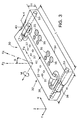
- Fig. 3 shows a load cell that includes force sensing elements arranged with respect to each other to respectively sense differently directed components of the applied forces.
- Fig. 3A is an exploded, end view of the load cell, which illustrates the connection between the load cell and upper and lower adapter plates.
- Fig. 4 is a cross-sectional view of an arm of the load cell taken along lines 4-4 of Fig. 3.
- Fig. 5 schematically shows electrical connections between a plurality of force sensing elements of the load cell, and between the elements and external circuitry.
- Fig. 6 is useful in understanding the operation of the load cell to determine tension forces in the web.
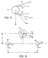
- Figs. 7 and 8 illustrate the use of the load cell to determine a force moment applied by the load.
- a web 10 of material is transported between spools of web processing machinery by rollers 12, only one of which is shown (the remainder of the machine is not shown).
- Roller 12 is rotated by a shaft 14 in either direction 16 to transport web 10.
- Each end of shaft 14 is supported by a bearing 18 nested within a so-called “pillow block” 20.
- the forces applied by web 10, illustrated as vector F R directed at angle ⁇ with respect to the vertical (z) axis, are measured by load cell 30, which is positioned between an upper bearing plate 22 and a lower bearing plate 24 beneath pillow block 20.
- load cell 30 comprises a planar, rectangular member 32 which receives the forces applied by web 10 (i.e., the load) and supports a plurality of force sensing elements (in this embodiment, strain gages) arranged to sense differently directed components of the forces.
- the force sensing elements sense the components of force F R applied along the z-axis (F z ) and along the x-axis (F x ) (the coordinate system of load cell 30 is shown to the left of the load cell in Fig. 3).
- Circuitry shown in Fig. 5 and discussed below responds to electrical signals produced by the force sensing elements in response to force components F z and F x to determine the magnitude and direction ( ⁇ ) of the overall force F R applied by web 10 and/or the tension in the web.
- Load cell member 32 includes a pair of elongated sections 34, 36 that extend along the x-axis and lie in the x-y plane.
- the opposite end regions of sections 34, 36 are interconnected by tubular arms 38, 40 which extend in parallel along the y-axis, orthogonally to sections 34, 36. Between their end regions, sections 34, 36 are spaced from each other by a slot 42.
- Sections 34, 36 and arms 38, 40 are cast or machined from a single, unitary body of stainless steel to eliminate undesirable stresses that might otherwise arise from misalignments and tolerance build-up.
- Load cell 30 is positioned beneath pillow block 20 so that roller shaft 14 (which extends along the y-axis) is positioned mid-way between arms 38, 40.
- member 32 is sandwiched between upper and lower bearing plates 22, 24 and spaced therefrom by sixteen washers 33 (eight washers for each section 34, 36).
- Section 34 is connected to lower bearing plate 24 by bolts 39.
- the heads of bolts 39 pass though holes in upper bearing plate 22 and are received in counterbored holes 35 in section 34.
- the threaded shafts of bolts 39 pass through washers 33 and are received by threaded holes in lower bearing plate 24.
- section 36 is connected to upper bearing plate 22 by bolts 39.
- the threaded shafts of bolts 39 are received by threaded holes in upper bearing plate 22 via washers 33.
- the heads of bolts 39 pass through holes in lower bearing plate 24 and are received in counterbored holes 37 on the underside of section 36 through holes 37.
- Washers 33 concentrate the loading forces applied via adapter plates 22, 24 and ensure that each adapter plate 22, 24 contacts only one of the sections (i.e., that adapter plate 22 contacts only section 36, and not section 34, and that adapter plate 24 contacts only section 34 and not section 36). This arrangement (along with the presence of slot 42 between sections 34, 36) ensures that the loading forces applied to sections 34, 36 induce shear forces in arms 38, 40.
- Member 32 has a low profile, e.g., with a height dimension H of approximately 1 1/4 inches. Thus, even taking into account the thickness of washers 33 (e.g., 1/8 inch), the total space between adapter plates 22, 24 needed to accommodate load cell 30 is only about 1 1/2 inches.
- the length L and width W dimensions of member 32 are selected (e.g., 12-14 inches and 6 inches, respectively) to approximate the footprint of a standard-sized pillow block. As a result, member 32 can easily be retrofit beneath pillow block 20 without significantly altering the location (e.g., the height) of roller 12 (Fig. 1).
- a passage 50 extends axially through each arm 38, 40 so that each arm is tubular.
- Each passage 50 is circular in cross-section and is centered about y-axis to define an annular interior surface 52 which is subjected to strain in response to the forces F R applied by the load.
- each arm 38, 40 i.e., equidistantly between sections 34, 36
- a pair of strain gages 60, 70 are attached to surface 52 and positioned so that their direction of maximum sensitivity is aligned with the z-axis and the x-axis, respectively. That is, strain gages 60, 70 independently sense the strain induced in surface 52 by components F z and F x , respectively, of force F R .
- arms 38, 40 support two pairs of strain gages, with one strain gage 60 of each pair being arranged to sense a force component directed along the z-axis, and the other strain gage 70 in each pair being arranged to independently sense a force component directed along the x-axis.
- the tubular nature of arms 38, 40 facilitates sealing passages 50 (the seals are not shown) to protect strain gages 60, 70 from adverse ambient conditions (e.g., moisture and corrosives).
- each strain gage 60 includes four strain sensitive resistors 62, 64, 66, 68 arranged in a bridge. Resistors 62, 64 are attached to an upper region of surface 52 and symmetrically arranged about the z-axis. Resistors 66, 68 are attached to a lower region of surface 52, directly opposite to resistors 62, 64, and are also symmetrically positioned about the z-axis.
- Each strain gage 70 includes four strain sensitive resistors 72, 74, 76, 78 arranged in a bridge. Resistors 72, 74 are attached to a left side region (as shown in Fig. 4) of surface 52 and are symmetrically arranged about the x-axis.
- Resistors 76, 78 are attached to a right side region of surface 52, directly opposite to resistors 72, 74, and are also symmetrically positioned about the x-axis.
- the circular shape of surface 52 and the symmetrical positioning of the strain sensitive resistors enables strain gages 60, 70 to have substantially equal sensitivity to respective force components F z and F x .
- Strain gages 60 are electrically connected together as shown in Fig. 5 to receive a reference input voltage V i and generate an output voltage V o .
- strain gages 70 are electrically connected together as shown in Fig. 5 to receive a reference input voltage V i and generate an output voltage V o .
- Output voltages V o of strain gages 60, 70 respectively represent the strain induced in surfaces 52 of arms 38, 40 in by force components F z and F x .
- the processing of output voltages V o is described in more detail below, but briefly, output voltages V o are processed by circuits 80, 82 external to member 32 to produce signals 82, 86 that respectively represent force component F z and force component F x .
- Signals 82, 86 are applied to external circuitry 88, which responds by producing an output signal 90 representative of the magnitude and the direction (angle ⁇ ) of force F R .
- the connections between strain gages 60, 70 and the external circuits are provided by cables (such as cable 98, Fig. 3A) connected to fittings at one end of each passage 50.
- strain gages 60, 70 are equally sensitive to force components F z and F x , respectively. Accordingly, the output voltages produced by strain gages 60, 70 accurately represent the strain induced in surfaces 52 in response to these force components.
- the average of the sensed strain is a measure of the sum of S 1 and S 2 , divided by the number of sensors (in this case, two).
- Circuits 80, 84 apply equation (2) to the respective output voltages V o of strain gages 60, 70 to determine F z and F x in a known manner.
- Force components F z and F x are related to overall force F R and angle ⁇ as follows:
- F x F R (cos ⁇ )
- F z F R (sin ⁇ )
- circuitry 88 determines the magnitude of force F R as:
- F R ⁇ (F x 2 + F z 2 )
- force F R represents the total forces applied to load cell 30 by web 10, including the weight (W) of web 10, roller 12, and pillow block 20 and the tension (F 1 ) in web 10.
- tension forces F 1 can be derived from F R , it often desirable determine the web tension forces directly from components F z and F x . This determination is straightforward, and can be made by circuitry 88 using either signal 82 (F z ) or signal 86 (F x ) :
- F z W + F 1 (sin ⁇ ) - F 1 (sin ⁇ )
- strain gages 60, 70 and circuitry 80, 84, 88 may also be connected to enable the circuitry to determine force moment M about the y-axis of roller 12.
- Fig. 8 illustrates the relationship between force components F z and F x , the spacing L between arms 38, 40, and the height H of roller 12 with respect to the plane of the load cell.
- Force component F x is the sum of the individual X-axis force components (F x1 and F x2 ) measured by strain gages 70
- force component F z is the sum the individual Z-axis force components (F z1 and F z2 ) measured by strain gages 60.
- Fig. 7 shows the appropriate connections between the outputs of strain gages 60, 70 and circuits 80, 84 which enable the measurement of individual vertical force components F z1 and F z2 to be made. (The reference voltages applied to the strain gages are not illustrated.) If desired, the outputs of strain gages 70 can be individually connected to circuit 84, rather than ganged together as shown in Fig. 7.
- circuitry 80, 84, 88 may calculate the torque on roller 12 by determining the difference between the vertical force component F z1 measured by strain gage 60 in arm 38 and vertical force component F z2 strain gage 60 in arm 40.
- load cell 30 is highly versatile and can be used at locations throughout the processing machinery. For example, identical load cells 30 can be used to measure web tension at several rollers 12 in the machinery, regardless of the orientations and angles of the rollers. That is, load cell 30 is equally suited for use in situations in which either F z or F x is zero. Although one set of strain gages 60, 70 would be inoperative, the output signal derived from the other strain gages can be used to determine forces such as web tension. Thus, there is no need to use separate horizontally sensitive and vertically sensitive load cells in such situation, or to orient the strain gages in a load cell so that their direction of maximum sensitivity is aligned with the direction of the applied force.
- strain gages such as semiconductor strain gages
- force sensing elements such as capacitive, inductive, and optical force sensing elements
- Load cell 30 can be used in other applications, such as with other types of continuously processed materials (such as strands) and other kinds of processing machinery. Examples include manufacturing machinery for textiles, asphalt roof shingles, wall board, sheet rock, and conveyor belts.
- load cell member 30 Materials other than stainless steel may be used for load cell member 30.
- member 30 can be made from spring steel, alloy steel, beryllium copper, aluminum, or other suitable materials which provide an acceptable relationship between applied force and displacement.
- Sections 34, 36 and arms 38, 40 may be assembled from individual components, rather than formed as a unitary body. Only a single arm 38, 40 and a single set of strain gages 60, 70 may be used, if desired.
- Load cell 30 need not be centered under the pillow block, with the load positioned equidistantly between arms 38, 40. Indeed, because the outputs of the strain gages of the two arms are averaged as described above, load cell 30 is insensitive to such variations in load position.
Landscapes
- Physics & Mathematics (AREA)
- General Physics & Mathematics (AREA)
- Force Measurement Appropriate To Specific Purposes (AREA)
- Measurement Of Force In General (AREA)
Applications Claiming Priority (2)
| Application Number | Priority Date | Filing Date | Title |
|---|---|---|---|
| US130157 | 1998-08-06 | ||
| US09/130,157 US6422096B1 (en) | 1998-08-06 | 1998-08-06 | Load cell |
Publications (2)
| Publication Number | Publication Date |
|---|---|
| EP0978714A2 true EP0978714A2 (fr) | 2000-02-09 |
| EP0978714A3 EP0978714A3 (fr) | 2000-06-21 |
Family
ID=22443331
Family Applications (1)
| Application Number | Title | Priority Date | Filing Date |
|---|---|---|---|
| EP99306057A Withdrawn EP0978714A3 (fr) | 1998-08-06 | 1999-07-30 | Cellule de charge |
Country Status (2)
| Country | Link |
|---|---|
| US (1) | US6422096B1 (fr) |
| EP (1) | EP0978714A3 (fr) |
Cited By (3)
| Publication number | Priority date | Publication date | Assignee | Title |
|---|---|---|---|---|
| DE102010002742A1 (de) | 2010-03-11 | 2011-09-15 | Voith Patent Gmbh | Bahnzugmesseinrichtung |
| CN106404262A (zh) * | 2016-11-18 | 2017-02-15 | 桂林电子科技大学 | 一种可测受力角度的动辊张力传感器及测量方法 |
| WO2019020307A1 (fr) * | 2017-07-24 | 2019-01-31 | Festool Gmbh | Outil électrique et procédé |
Families Citing this family (15)
| Publication number | Priority date | Publication date | Assignee | Title |
|---|---|---|---|---|
| US6711960B2 (en) * | 2001-05-31 | 2004-03-30 | Teac Corporation | Compact load cell with arm tension absorption means and arm reinforcement means |
| JP4907050B2 (ja) * | 2003-03-31 | 2012-03-28 | 株式会社ワコー | 力検出装置 |
| JP4387691B2 (ja) | 2003-04-28 | 2009-12-16 | 株式会社ワコー | 力検出装置 |
| US7202425B2 (en) * | 2005-04-13 | 2007-04-10 | The Montalvo Corporation | Under-pillow-block load cell |
| DE102006053949A1 (de) * | 2006-11-15 | 2008-05-21 | Siemens Ag | DMS-Faser-Gurt |
| ES2773065T3 (es) * | 2010-10-15 | 2020-07-09 | Yamato Scale Co Ltd | Célula de carga con protección contra sobrecargas |
| US9250146B2 (en) * | 2013-02-12 | 2016-02-02 | Western New England University | Multidimensional strain gage |
| US11054325B2 (en) * | 2013-10-05 | 2021-07-06 | Bertec Limited | Force measurement system |
| US11262258B2 (en) | 2013-10-05 | 2022-03-01 | Bertec Limited | Force measurement system |
| US11604106B2 (en) | 2013-10-05 | 2023-03-14 | Bertec Limited | Force measurement assembly |
| JP6600756B2 (ja) * | 2015-11-30 | 2019-10-30 | リンク エンジニアリング カンパニー | 高荷重高分解能計装スピンドル又はロードセル |
| US10724911B1 (en) * | 2017-06-16 | 2020-07-28 | Conveyor Dynamics, Inc. | Belt tension measuring device |
| US11850078B1 (en) | 2020-01-04 | 2023-12-26 | Bertec Corporation | Force measurement system |
| US12158382B1 (en) | 2020-01-04 | 2024-12-03 | Bertec Corporation | Force measurement system |
| US20220002107A1 (en) * | 2020-07-01 | 2022-01-06 | CSG Holding, Inc. | Webtension transducer load cell with integrated data interface |
Citations (4)
| Publication number | Priority date | Publication date | Assignee | Title |
|---|---|---|---|---|
| US3602866A (en) | 1968-12-18 | 1971-08-31 | Erwin J Saxl | Force transducer |
| US4454769A (en) | 1981-02-26 | 1984-06-19 | Vibro-Meter Sa | Radial force measuring cell |
| US4483203A (en) | 1983-06-02 | 1984-11-20 | Amp Incorporated | Multi-axis force transducer |
| JPH0419529B2 (fr) | 1981-04-09 | 1992-03-30 | Olympus Optical Co |
Family Cites Families (34)
| Publication number | Priority date | Publication date | Assignee | Title |
|---|---|---|---|---|
| DE273549C (fr) | ||||
| US3422671A (en) | 1966-05-04 | 1969-01-21 | Revere Corp America | Load cell |
| US3771359A (en) | 1972-05-17 | 1973-11-13 | Gse Inc | Load cell |
| SE401560B (sv) | 1976-08-16 | 1978-05-16 | Asea Ab | Forfarande for minimering av meftel vid bandspenningsmetning |
| US4182168A (en) | 1978-08-31 | 1980-01-08 | Comptrol, Inc. | Thrust-torque transducer |
| US4326424A (en) | 1979-03-30 | 1982-04-27 | Cleveland Machine Controls, Inc. | Web tension transducer arrangement |
| SE420130B (sv) | 1980-01-24 | 1981-09-14 | Asea Ab | Optiskt metdon for metning av kraft eller tryck |
| US4467661A (en) | 1981-10-02 | 1984-08-28 | Maatschappij Van Berkel's Patent N.V. | Load cell with overload protection system |
| SE438733B (sv) | 1982-03-05 | 1985-04-29 | Bofors Ab | Lastcell av skjuvkrafttyp |
| SE430541B (sv) | 1982-03-24 | 1983-11-21 | Asea Ab | Temperaturkompenserad magnetoelastisk kraftmetare |
| US4487079A (en) | 1983-02-22 | 1984-12-11 | Comptrol, Incorporated | Dual range force transducer |
| SE455885B (sv) | 1986-12-15 | 1988-08-15 | Asea Ab | Magnetoelastisk kraftgivare |
| SE455886B (sv) | 1986-12-15 | 1988-08-15 | Asea Ab | Magnetoelastisk kraftgivare |
| SE457116B (sv) | 1987-04-30 | 1988-11-28 | Asea Ab | Magnetoelastisk kraftgivare |
| SE468144B (sv) | 1987-08-24 | 1992-11-09 | Asea Ab | En kaenslighetsdriftkompenserad magnetoelastisk kraftgivare |
| US4854179A (en) | 1987-10-02 | 1989-08-08 | Blh Electronics, Inc. | Coaxial load cell |
| US4899599A (en) | 1987-12-07 | 1990-02-13 | Magnetic Power Systems, Inc. | Strain force sensor means |
| DE3822486A1 (de) | 1988-07-02 | 1990-01-04 | Koenig & Bauer Ag | Einrichtung zum messen der bahnspannung einer warenbahn |
| JP2699096B2 (ja) | 1988-12-19 | 1998-01-19 | 株式会社ブリヂストン | 測定装置 |
| US4982185A (en) | 1989-05-17 | 1991-01-01 | Blh Electronics, Inc. | System for synchronous measurement in a digital computer network |
| US5005429A (en) | 1989-09-21 | 1991-04-09 | Blh Electronics, Inc. | Weigh module |
| SE465185B (sv) | 1989-12-21 | 1991-08-05 | Asea Brown Boveri | Foerfarande jaemte anordning foer detektering av och skydd mot inverkan av stoerande statiska och kvasistatiska magnetfaelt paa maetning med kraft- och vridmomentgivare |
| US5007295A (en) | 1990-01-03 | 1991-04-16 | Asea Brown Boveri Ab | Magnetoelastic force transducer |
| US5045827A (en) | 1990-03-28 | 1991-09-03 | Blh Electronics, Inc. | Low-force transducer |
| JPH0419592A (ja) | 1990-05-14 | 1992-01-23 | Seikosha Co Ltd | 走行計測装置 |
| US5128676A (en) | 1990-06-05 | 1992-07-07 | Blh Electronics, Inc. | Variable conversion rate analog-to-digital converter |
| US5159841A (en) | 1990-11-01 | 1992-11-03 | The Montalvo Corporation | Web tension sensor |
| US5257550A (en) | 1990-11-01 | 1993-11-02 | The Montalvo Corporation | Web tension sensor |
| US5186061A (en) | 1991-01-23 | 1993-02-16 | The Montalvo Corporation | Transducer beam and beam assembly |
| US5315882A (en) * | 1992-03-23 | 1994-05-31 | Mts Systems Corporation | Six axis load cell |
| SE470196B (sv) | 1992-05-05 | 1993-11-29 | Asea Brown Boveri | Tredimensionell magnetoelastisk kraftgivare |
| US5419210A (en) | 1993-03-09 | 1995-05-30 | Blh Electronics, Inc. | High capacity weigh module |
| US5837946A (en) * | 1995-06-16 | 1998-11-17 | Weigh-Tronix, Inc. | Force sensitive scale and dual load sensor cell for use therewith |
| US5648617A (en) * | 1995-08-25 | 1997-07-15 | Applied Robotics, Inc. | Single axis robot force sensor assembly |
-
1998
- 1998-08-06 US US09/130,157 patent/US6422096B1/en not_active Expired - Fee Related
-
1999
- 1999-07-30 EP EP99306057A patent/EP0978714A3/fr not_active Withdrawn
Patent Citations (4)
| Publication number | Priority date | Publication date | Assignee | Title |
|---|---|---|---|---|
| US3602866A (en) | 1968-12-18 | 1971-08-31 | Erwin J Saxl | Force transducer |
| US4454769A (en) | 1981-02-26 | 1984-06-19 | Vibro-Meter Sa | Radial force measuring cell |
| JPH0419529B2 (fr) | 1981-04-09 | 1992-03-30 | Olympus Optical Co | |
| US4483203A (en) | 1983-06-02 | 1984-11-20 | Amp Incorporated | Multi-axis force transducer |
Cited By (9)
| Publication number | Priority date | Publication date | Assignee | Title |
|---|---|---|---|---|
| DE102010002742A1 (de) | 2010-03-11 | 2011-09-15 | Voith Patent Gmbh | Bahnzugmesseinrichtung |
| WO2011110416A2 (fr) | 2010-03-11 | 2011-09-15 | Voith Patent Gmbh | Dispositif de mesure de la tension d'une bande |
| WO2011110416A3 (fr) * | 2010-03-11 | 2012-03-08 | Voith Patent Gmbh | Dispositif de mesure de la tension d'une bande |
| CN106404262A (zh) * | 2016-11-18 | 2017-02-15 | 桂林电子科技大学 | 一种可测受力角度的动辊张力传感器及测量方法 |
| WO2019020307A1 (fr) * | 2017-07-24 | 2019-01-31 | Festool Gmbh | Outil électrique et procédé |
| CN110944799A (zh) * | 2017-07-24 | 2020-03-31 | 费斯托工具有限责任公司 | 电动工具和方法 |
| US20210154819A1 (en) * | 2017-07-24 | 2021-05-27 | Festool Gmbh | Power tool and method |
| CN110944799B (zh) * | 2017-07-24 | 2021-11-26 | 费斯托工具有限责任公司 | 电动工具和方法 |
| US11697200B2 (en) * | 2017-07-24 | 2023-07-11 | Festool Gmbh | Power tool and method |
Also Published As
| Publication number | Publication date |
|---|---|
| EP0978714A3 (fr) | 2000-06-21 |
| US6422096B1 (en) | 2002-07-23 |
Similar Documents
| Publication | Publication Date | Title |
|---|---|---|
| US6422096B1 (en) | Load cell | |
| US4454770A (en) | Torque-insensitive load cell | |
| US9605993B2 (en) | Load cell with a means to compensate for errors due to misalignment | |
| EP0101425B1 (fr) | Cellule de charge sensible au cisaillement | |
| US5777240A (en) | Load cell and load cell beam assembly | |
| US5925832A (en) | Torsional sensing load cell | |
| EP2597441A2 (fr) | Cellule de charge et leurs applications | |
| KR20180138150A (ko) | 엘리베이터 카 하중의 표시를 제공하는 엘리베이터 종단 조립체 | |
| US5076376A (en) | Strain gauge weighing device | |
| GB1562620A (en) | Force sensing mechanism for use in material handling apparatus | |
| CN102596785A (zh) | 用于测试张力元件绳索的多个张力元件中的拉伸应力的方法和装置 | |
| US4655305A (en) | Strain gage type platform sensor | |
| EP0805961B1 (fr) | Technique et appareil de mesure des forces sur deux axes et application a la mesure de la force de traction et d'un angle de deflexion variable dans un motif continu | |
| EP0253644B1 (fr) | Senseur de détermination de la solidité de matériaux en forme de bande | |
| US5228527A (en) | Force measurement assembly | |
| US20030131672A1 (en) | Load cell | |
| US4597460A (en) | Multiple load cell weighing structure | |
| WO1997004289A1 (fr) | Dispositif de mesure de contraintes et controle des charges de conteneurs de vehicules | |
| US4757867A (en) | Single load cell weighing systems | |
| US4580645A (en) | Constant moment weigh scale with misalignment compensator | |
| RU2145700C1 (ru) | Грузоприемное устройство весов | |
| EP3990874A1 (fr) | Ensemble cellule de charge planaire | |
| WO1993022632A1 (fr) | Dispositifs de mesure de charge | |
| CN110431389A (zh) | 输送和计量装置的校准 | |
| AU658778B2 (en) | Sole plate for bearing load measurement |
Legal Events
| Date | Code | Title | Description |
|---|---|---|---|
| PUAI | Public reference made under article 153(3) epc to a published international application that has entered the european phase |
Free format text: ORIGINAL CODE: 0009012 |
|
| AK | Designated contracting states |
Kind code of ref document: A2 Designated state(s): DE FR GB SE |
|
| AX | Request for extension of the european patent |
Free format text: AL;LT;LV;MK;RO;SI |
|
| PUAL | Search report despatched |
Free format text: ORIGINAL CODE: 0009013 |
|
| AK | Designated contracting states |
Kind code of ref document: A3 Designated state(s): AT BE CH CY DE DK ES FI FR GB GR IE IT LI LU MC NL PT SE |
|
| AX | Request for extension of the european patent |
Free format text: AL;LT;LV;MK;RO;SI |
|
| RIC1 | Information provided on ipc code assigned before grant |
Free format text: 7G 01L 5/16 A, 7G 01L 5/10 B, 7G 01L 1/22 B, 7G 01L 5/00 B |
|
| 17P | Request for examination filed |
Effective date: 20001221 |
|
| AKX | Designation fees paid |
Free format text: DE FR GB SE |
|
| 17Q | First examination report despatched |
Effective date: 20010731 |
|
| 17Q | First examination report despatched |
Effective date: 20010731 |
|
| STAA | Information on the status of an ep patent application or granted ep patent |
Free format text: STATUS: THE APPLICATION IS DEEMED TO BE WITHDRAWN |
|
| 18D | Application deemed to be withdrawn |
Effective date: 20150203 |