EP0979184B1 - Volet de deploiement de coussin gonflable de securite integre au siege - Google Patents
Volet de deploiement de coussin gonflable de securite integre au siege Download PDFInfo
- Publication number
- EP0979184B1 EP0979184B1 EP98920906A EP98920906A EP0979184B1 EP 0979184 B1 EP0979184 B1 EP 0979184B1 EP 98920906 A EP98920906 A EP 98920906A EP 98920906 A EP98920906 A EP 98920906A EP 0979184 B1 EP0979184 B1 EP 0979184B1
- Authority
- EP
- European Patent Office
- Prior art keywords
- air bag
- seat
- rim
- deployment
- door
- Prior art date
- Legal status (The legal status is an assumption and is not a legal conclusion. Google has not performed a legal analysis and makes no representation as to the accuracy of the status listed.)
- Expired - Lifetime
Links
- 239000000463 material Substances 0.000 claims description 75
- 238000009958 sewing Methods 0.000 claims description 7
- 238000004026 adhesive bonding Methods 0.000 claims description 5
- 238000000034 method Methods 0.000 claims description 5
- 239000002184 metal Substances 0.000 description 5
- 238000004873 anchoring Methods 0.000 description 2
- 238000010276 construction Methods 0.000 description 2
- 239000006260 foam Substances 0.000 description 2
- 239000004033 plastic Substances 0.000 description 2
- 239000003292 glue Substances 0.000 description 1
- 238000012986 modification Methods 0.000 description 1
- 230000004048 modification Effects 0.000 description 1
- 239000002991 molded plastic Substances 0.000 description 1
- 230000002093 peripheral effect Effects 0.000 description 1
- 230000001681 protective effect Effects 0.000 description 1
- 230000003014 reinforcing effect Effects 0.000 description 1
Images


Classifications
-
- B—PERFORMING OPERATIONS; TRANSPORTING
- B60—VEHICLES IN GENERAL
- B60R—VEHICLES, VEHICLE FITTINGS, OR VEHICLE PARTS, NOT OTHERWISE PROVIDED FOR
- B60R21/00—Arrangements or fittings on vehicles for protecting or preventing injuries to occupants or pedestrians in case of accidents or other traffic risks
- B60R21/02—Occupant safety arrangements or fittings, e.g. crash pads
- B60R21/16—Inflatable occupant restraints or confinements designed to inflate upon impact or impending impact, e.g. air bags
- B60R21/20—Arrangements for storing inflatable members in their non-use or deflated condition; Arrangement or mounting of air bag modules or components
- B60R21/207—Arrangements for storing inflatable members in their non-use or deflated condition; Arrangement or mounting of air bag modules or components in vehicle seats
-
- B—PERFORMING OPERATIONS; TRANSPORTING
- B60—VEHICLES IN GENERAL
- B60R—VEHICLES, VEHICLE FITTINGS, OR VEHICLE PARTS, NOT OTHERWISE PROVIDED FOR
- B60R21/00—Arrangements or fittings on vehicles for protecting or preventing injuries to occupants or pedestrians in case of accidents or other traffic risks
- B60R2021/0002—Type of accident
- B60R2021/0006—Lateral collision
-
- B—PERFORMING OPERATIONS; TRANSPORTING
- B60—VEHICLES IN GENERAL
- B60R—VEHICLES, VEHICLE FITTINGS, OR VEHICLE PARTS, NOT OTHERWISE PROVIDED FOR
- B60R21/00—Arrangements or fittings on vehicles for protecting or preventing injuries to occupants or pedestrians in case of accidents or other traffic risks
- B60R21/02—Occupant safety arrangements or fittings, e.g. crash pads
- B60R21/16—Inflatable occupant restraints or confinements designed to inflate upon impact or impending impact, e.g. air bags
- B60R21/20—Arrangements for storing inflatable members in their non-use or deflated condition; Arrangement or mounting of air bag modules or components
- B60R21/215—Arrangements for storing inflatable members in their non-use or deflated condition; Arrangement or mounting of air bag modules or components characterised by the covers for the inflatable member
- B60R21/2165—Arrangements for storing inflatable members in their non-use or deflated condition; Arrangement or mounting of air bag modules or components characterised by the covers for the inflatable member characterised by a tear line for defining a deployment opening
Definitions
- the present invention relates generally to air bag systems and more specifically to a seat-integrated air bag deployment door configured to be attached to the seat material for side impact occupant protection systems.
- WO 97/04994 discloses a side air bag deployment assembly embedded in a seat side portion wherein deployment of the air bag is achieved by rip-opening a rim, i.e. a sutured portion defining a passage through the seat skin material, by virtue of the expansion pressure of the same air bag.
- An internal belt-like body is provided for concentrating the expansion pressure of the air bag on the rim.
- an air bag module capable of deploying an air bag through an air bag deployment door is positioned within the seat back.
- Conventional air bag deployment doors consist of a frame affixed to the seat back which defines the perimeter of the deployment opening.
- a soft cover or a rigid door is affixed to the frame and used to close and seal the deployment opening.
- the frame is generally comprised of sheet metal or molded plastic to stiffen and stabilize the seat material in the regions extending around the perimeter of the deployment opening.
- the frame is stabilized by anchoring flanges or tabs connecting the frame to a rigid housing within the seat back. This type of construction presents difficulties in aligning the seat material around the frame, since the seat material often pleats, folds or puckers along the seat material-frame boundary.
- the use of a metal frame and a rigid housing for anchoring the frame places metal components within the seat back which may cause seat discomfort to the occupant. Also, the metal frame is not attached to the seat material and may shift. As a result, it is difficult to know the exact location through which the inflating air bag will deploy through the seat seam.
- a further object of the invention is to provide a side impact air bag deployment door which is attached to the seat material and is capable of allowing the air bag to quickly and effectively deploy through a consistent route of deployment.
- the invention includes a soft, flexible seat-integrated air bag deployment door or cover having a rim and crown construction.
- the deployment door is preferably sewn or glued to the seat material about an opening in the material.
- the door localizes the energy of an inflating air bag to a tear region or seam of the soft door or cover.
- the tear region tears during deployment of the air bag, thereby permitting the air bag to deploy therethrough.
- the seat-integrated air bag deployment door is compatible with seat design and does not require any metal components to cause discomfort to the occupant.
- the seat material extends across the cover and the cover is used to rip open the seat material permitting the air bag to expand therethrough.
- the present invention also includes a method of attaching the seat-integrated air bag deployment door to the seat material of a vehicle seat.
- This method comprises the steps of positioning the deployment door on the seat material substantially over a cutout portion in the vehicle seat material or at a location in the seat material which will be torn open by the door; positioning the seat material around a rim wall portion of the deployment door, such that the seat material lies beneath a front planar surface of the rim (or in the case of the alternate embodiment over the rim and the rest of the cover); and sewing or gluing the front planar surface to the seat material.
- the present invention is applicable to various air bag modules constructed to deploy an air bag into the passenger compartment during a side impact collision, such as the "Side Impact Soft Pack Air Bag Module" which is described and illustrated by U.S. Patent No. 5,547,214 issued to Zimmerman, II et al., the contents of which are incorporated herein by reference.
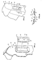
- FIGURE 1 shows a preferred embodiment of the seat-integrated air bag deployment door (or cover) generally indicated by numeral 10 and spaced apart from a seat back covering material 18.
- the door 10 is preferably made from a soft, pliable plastic (such as TPO and TPE) capable of withstanding high temperatures.
- the covering material 18 is inside-out.
- the material 18 includes a cutout portion or opening 16 in a side portion 15 thereof that will be installed facing a side of the vehicle with edges 17 of the material folded back to reinforce the opening 16.
- the location of the opening 16 in the side 15 of the material is chosen such that when the material is installed upon the seat back, the opening (and the attached door) are positioned above a deployment channel in the seat (see FIGURE 5A).
- the seat-integrated air bag deployment door 10 of the present invention is formed, molded or extruded, preferably of a plastic material, having a rectangular, peripheral collar or rim 22 with an outer boundary 24 measuring approximately 200 mm (8 inches) in length and 125 mm (5 inches) in width. The width of the rim is approximately 25 mm (1 inch).
- the door 22 further includes integrally formed tapered walls 30, which extend from an inner boundary or edge 26 of the rim, and terminate at a crown 32.
- the walls 30 have a depth of about 3 mm (0.125 inch).
- a front face 28 (shown more clearly in FIGURE 4A) of the door 10 is identified as 28.
- the edge 26 and walls 30 define the perimeter of a deployment channel 34 through which the air bag will expand.
- the walls 30 and top or crown 32 of the door 10 are inserted into the opening 16 with the front face 28 of the rim 22 placed against the seat covering material surrounding the opening 16.
- the rim 22 is thereafter secured to the material 18.
- the material 18, is folded back (at 17) upon itself to provide at least a double material layer 36 of material about the opening 16.
- FIGUREs 2 and 3 illustrate two preferred methods for permanently attaching the deployment door 10 to the double layer 36 of seat material 18.
- the rim 22 of the deployment door 10 is attached to the seat material 18 by sewing. Stitches 38 fasten the rim 22 of the deployment door 10 directly to the seat material 18.
- the rim 22 is attached to the seat material 18 by gluing. Glue 40 is applied directly to the seat material 18 (or to the rim of the cover) and the deployment door 10 is affixed thereto.
- the covering material of FIGURES 2 and 3 is shown inside-out. The covering material is turned right-side-out (see FIGURE 4) and fitted about a seat back generally shown as 12 of an automotive seat 14.
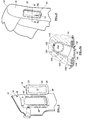
- FIGURE 4A is a partial cross-sectional view illustrating the deployment door 10 attached to the seat material 18 by sewing and FIGURE 5 shows the deployment door 10 attached to the seat material 18 by gluing.
- FIGURE 5A shows the location of an air bag module 100 (which is equally applicable to FIGURE 4A) including an air bag 102 and inflator 104 positioned within the pocket 106 formed in the seat foam 108 of the seat back 12. The inflator 104 is connected to a seat frame 110 at the desired location.
- the covering material 18 is installed upon the foam 108, the deployment door 10 is positioned at the opening 114 (deployment opening) of a channel 109.
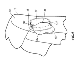
- the deployment door 10 includes a tear region 45 that includes an upper 120, lower 122 and forward edge 124 of the walls or crown of the door.
- the method of attaching the flexible soft cover 42 to the deployment door 10 entails sewing the various panels of seat covering material together to from a covering for a seat back, locating an opening in a side panel 15 of the assembled covering material such that the opening will be aligned to a deployment channel formed in the seat after the covering material is positioned upon the seat back, reinforcing the edges of the covering material about the opening 16 and attaching the door 10 to the covering material and locating the tear regions of the door 10 over the deployment channel opening 114.
- This configuration enables the energy created by the inflating air bag 44 to cause only the left side of the flexible soft cover 10 to tear open.
- the right edge of the top 32 does not include a tear region and acts as a hinge about which the torn open portions of the door 10 may rotate.
- the air bag 102 deploys only form the left side of the flexible soft cover 42.
- FIGUREs 7-8 An alternative embodiment of the invention is shown in FIGUREs 7-8.
- a tear seam 48 (dotted line) primarily extends through the center of the flexible soft door 10.
- the tear region or tear seam 48 is formed in an H pattern defining two door panels 50 in the door 10.
- the air bag 44 inflates it creates energy which forces the tear seam 48 to tear and separate the two door panels 50.
- this alternate embodiment with the two door panels could be used in the embodiment of the earlier figures.
- the seat material 18 overlays and conceals the flexible soft cover or door 10 from view, as illustrated in FIGURE 7A. Therefore, during deployment of the air bag 102, the seat material 18 overlaying the flexible soft cover 10 must be torn away by the torn edges of each of the panels 50 proximate the tear seam 48.
- FIGURE 8 shows the door 10 of FIGURE 7 after the air bag has been inflated and the seat material 18 has been ripped open allowing the air bag to expand therethrough.
Landscapes
- Engineering & Computer Science (AREA)
- Mechanical Engineering (AREA)
- Air Bags (AREA)
Claims (13)
- Assemblage de déploiement d'un coussin d'air pour un siège de véhicule (14), comprenant:un couvercle (10) comportant un rebord (22) définissant un passage central, et un sommet (32) remontant au-dessus du rebord (22), le rebord (22) étant fixé directement et uniquement à une partie du matériau de recouvrement du siège (18) du siège du véhicule (14), et lors de l'assemblage du matériau sur un siège du véhicule, le rebord et le sommet sont superposés à un canal de déploiement (34, 109) du siège (14), à travers lequel un coussin d'air (102) est déployé, caractérisé en ce que le couvercle (10) comporte une région affaiblie définissant une couture à déchirure (45) qui est déchirée au cours du déploiement dudit coussin d'air, permettant la dilatation correspondante du coussin d'air.
- Assemblage de déploiement d'un coussin d'air selon la revendication 1, dans lequel le matériau de recouvrement englobe une ouverture (16), le rebord du couvercle de déploiement (10) étant en général fixé sur le matériau près des bords de l'ouverture (16).
- Assemblage de déploiement d'un coussin d'air selon la revendication 1, dans lequel le matériau de recouvrement du siège est superposé au rebord et au sommet dudit couvercle (10).
- Assemblage de déploiement d'un coussin d'air selon l'une quelconque des revendications 1 à 3, dans lequel ledit rebord (22) englobe une partie de paroi à extension (30) positionnée dans l'ouverture dans le matériau.
- Assemblage de déploiement d'un coussin d'air selon l'une quelconque des revendications 1 à 4, dans lequel ledit rebord (22) est fixé sur le matériau du siège (18) par couture.
- Assemblage de déploiement d'un coussin d'air selon l'une quelconque des revendications 1 à 4, dans lequel ledit rebord (22) est fixé sur le matériau du siège (18) par collage.
- Assemblage de déploiement d'un coussin d'air selon l'une quelconque des revendications précédentes, dans lequel le sommet (32) est relié à la partie de paroi (30) débordant hors du matériau de recouvrement.
- Assemblage de déploiement d'un coussin d'air selon la revendication 7, dans lequel ledit couvercle (10) est composé d'un matériau élastomère ou flexible.
- Assemblage de déploiement d'un coussin d'air selon la revendication 1, dans lequel ladite au moins une région à déchirure divise ledit couvercle (10) dans au moins deux sections (50) au cours du déploiement du coussin d'air (102), les bords déchirés des deux sections déchirées étant superposés au matériau de recouvrement.
- Assemblage de déploiement d'un coussin d'air selon la revendication 1, comportant un rebord (22) et une limite externe ainsi qu'une limite interne, ladite limite interne (26) définissant le périmètre d'une ouverture de déploiement, le rebord (22) étant destiné à être fixé sur un matériau de recouvrement du siège, de sorte que lors de l'ajustement du matériau de recouvrement sur un siège du véhicule, le rebord est aligné avec une partie entaillée ou un canal de déploiement (114) du siège du véhicule (14).
- Assemblage de déploiement d'un coussin d'air selon l'une quelconque des revendications précédentes, dans lequel ladite région à déchirure est déchirée le long d'un trajet prédéterminé s'étendant pratiquement le long d'une partie centrale de la partie supérieure du couvercle (10).
- Assemblage de déploiement d'un coussin d'air selon l'une quelconque des revendications précédentes, dans lequel le matériau du siège (18) est superposé au couvercle (10) et cache celui-ci.
- Procédé de fixation d'un couvercle de déploiement d'un coussin d'air (10) selon la revendication 1, comportant une partie de paroi (30) et un sommet (32), s'étendant à partir d'une surface plane (28) d'un rebord (22) et définissant le périmètre d'une région à déploiement pour un coussin d'air, comprenant les étapes ci-dessous:positionnement du couvercle de déploiement (10) sur le matériau de recouvrement du siège (18), de sorte que la région de déploiement est pratiquement alignée avec un canal de déploiement du siège du véhicule (14);agencement du matériau de recouvrement du siège (18) autour du rebord, de sorte que le matériau de recouvrement du siège (18) se situe au-dessous de la surface plane (28); etfixation, par couture ou collage, de la surface avant plane (28) sur le matériau du siège (18).
Applications Claiming Priority (3)
| Application Number | Priority Date | Filing Date | Title |
|---|---|---|---|
| US847269 | 1997-05-01 | ||
| US08/847,269 US5882033A (en) | 1997-05-01 | 1997-05-01 | Seat-integrated air bag deployment door |
| PCT/US1998/008635 WO1998049032A1 (fr) | 1997-05-01 | 1998-04-29 | Volet de deploiement de coussin gonflable de securite integre au siege |
Publications (3)
| Publication Number | Publication Date |
|---|---|
| EP0979184A1 EP0979184A1 (fr) | 2000-02-16 |
| EP0979184A4 EP0979184A4 (fr) | 2004-11-17 |
| EP0979184B1 true EP0979184B1 (fr) | 2006-05-31 |
Family
ID=25300224
Family Applications (1)
| Application Number | Title | Priority Date | Filing Date |
|---|---|---|---|
| EP98920906A Expired - Lifetime EP0979184B1 (fr) | 1997-05-01 | 1998-04-29 | Volet de deploiement de coussin gonflable de securite integre au siege |
Country Status (4)
| Country | Link |
|---|---|
| US (1) | US5882033A (fr) |
| EP (1) | EP0979184B1 (fr) |
| DE (1) | DE69834722T2 (fr) |
| WO (1) | WO1998049032A1 (fr) |
Families Citing this family (13)
| Publication number | Priority date | Publication date | Assignee | Title |
|---|---|---|---|---|
| US6007091A (en) * | 1997-11-20 | 1999-12-28 | Lear Corporation | Safety cushion assembly, specifically in a seating element for an automotive vehicle |
| US6089595A (en) * | 1997-12-09 | 2000-07-18 | Autoliv Asp, Inc. | Side impact airbag module |
| DE19910082C1 (de) * | 1999-03-08 | 2000-04-13 | Daimler Chrysler Ag | Stütze für einen Fahrzeugsitz |
| DE10321459A1 (de) * | 2003-05-13 | 2004-12-02 | Trw Occupant Restraint Systems Gmbh & Co. Kg | Sitzintegriertes Fahrzeuginsassen-Rückhaltesystem |
| DE10340508A1 (de) * | 2003-09-03 | 2005-03-31 | Bayerische Motoren Werke Ag | Fahrzeugsitz |
| DE102004020913B3 (de) * | 2004-04-28 | 2005-09-22 | Johnson Controls Gmbh | Fahrzeugsitz mit Abdeckblende |
| DE102004040236B4 (de) * | 2004-08-13 | 2017-11-16 | TAKATA Aktiengesellschaft | Seitenairbageinrichtung |
| JP2007185981A (ja) * | 2006-01-11 | 2007-07-26 | Takata Corp | 座席シート |
| US8171868B2 (en) * | 2009-04-02 | 2012-05-08 | GM Global Technology Operations LLC | Sewing method for seat cover |
| WO2010150449A1 (fr) * | 2009-06-24 | 2010-12-29 | 本田技研工業株式会社 | Siège de véhicule |
| DE102010063426A1 (de) * | 2010-12-17 | 2012-06-21 | Johnson Controls Gmbh | Fahrzeugsitz und Verfahren zur Herstellung eines Fahrzeugsitzes |
| US8567816B1 (en) * | 2012-12-19 | 2013-10-29 | Faurecia Interior Systems, Inc. | Airbag tear seam shapes |
| FR3061099B1 (fr) * | 2016-12-22 | 2019-05-31 | Renault S.A.S | Assemblage renforce d'une structure d'habillage a une ouverture realisee dans une paroi de garniture d'un vehicule. |
Family Cites Families (6)
| Publication number | Priority date | Publication date | Assignee | Title |
|---|---|---|---|---|
| US5451075A (en) * | 1994-06-29 | 1995-09-19 | Davidson Textron Inc. | Closure for an air bag assembly |
| DE69627684T2 (de) * | 1995-08-02 | 2004-04-08 | Toyoda Gosei Co., Ltd. | Seitenairbagvorrichtung |
| US5667242A (en) * | 1995-10-17 | 1997-09-16 | Trw Vehicle Safety Systems Inc. | Frame member for a seat mounted vehicle safety apparatus |
| DE19600278C1 (de) * | 1996-01-05 | 1997-01-09 | Daimler Benz Ag | Kraftfahrzeugsitz mit einer Airbagschutzeinrichtung |
| US5676394A (en) * | 1996-09-03 | 1997-10-14 | Morton International, Inc. | Seat trim deployment cover for side airbag module |
| DE29620382U1 (de) * | 1996-11-23 | 1997-01-16 | Kiddy GmbH Autokindersitze, 07356 Thimmendorf | Schonbezug für einen ein- oder mehrteiligen Kraftfahrzeugsitz |
-
1997
- 1997-05-01 US US08/847,269 patent/US5882033A/en not_active Expired - Fee Related
-
1998
- 1998-04-29 EP EP98920906A patent/EP0979184B1/fr not_active Expired - Lifetime
- 1998-04-29 WO PCT/US1998/008635 patent/WO1998049032A1/fr not_active Ceased
- 1998-04-29 DE DE69834722T patent/DE69834722T2/de not_active Expired - Fee Related
Also Published As
| Publication number | Publication date |
|---|---|
| US5882033A (en) | 1999-03-16 |
| DE69834722T2 (de) | 2007-05-16 |
| DE69834722D1 (de) | 2006-07-06 |
| EP0979184A4 (fr) | 2004-11-17 |
| EP0979184A1 (fr) | 2000-02-16 |
| WO1998049032A1 (fr) | 1998-11-05 |
Similar Documents
| Publication | Publication Date | Title |
|---|---|---|
| US9120411B2 (en) | Automotive seat foam pad assembly | |
| US7281735B2 (en) | Seat-integrated vehicle occupant restraint system and vehicle seat | |
| US5749597A (en) | Integral cover-deployment chute for side airbag module | |
| US7134686B2 (en) | Vehicle seat assembly | |
| US7290791B2 (en) | Vehicle seat assembly with air bag guide retainer | |
| US7322597B2 (en) | Vehicle seat assembly with separable air bag guide retainers | |
| US7540529B2 (en) | Vehicle seat assembly | |
| US4360223A (en) | Low mount, easily assembled, air bag passive restraint module | |
| US7597347B2 (en) | Airbag and airbag device | |
| US6257616B1 (en) | Headliner assembly | |
| US5447326A (en) | Vehicle door with pre-deployed air bag | |
| US7029027B2 (en) | Controlled tether arrangement for an airbag | |
| US5431435A (en) | Door panel air bag cover | |
| US6050636A (en) | Vehicle seat provided with a lateral airbag | |
| US20040007857A1 (en) | Inflatable airbag deployment guide | |
| US5882033A (en) | Seat-integrated air bag deployment door | |
| US20030047919A1 (en) | Cushion for protection of a vehicle occupant's head | |
| EP0761507A1 (fr) | Module de sac gonflable et volant de direction | |
| US5890734A (en) | Integral cover-deployment chute for side airbag module | |
| US7213837B2 (en) | Airbag module | |
| JPH0769149A (ja) | 助手席エアバッグ装置 | |
| KR20000048597A (ko) | 은폐식 에어백 커버의 전방 취약부 구조 | |
| EP0710591B1 (fr) | Porte sans jointure pour module de coussin d'air | |
| JP2003529492A (ja) | エアバッグシステムおよびそれを製作する方法 | |
| US5340149A (en) | Door assembly with integral tether |
Legal Events
| Date | Code | Title | Description |
|---|---|---|---|
| PUAI | Public reference made under article 153(3) epc to a published international application that has entered the european phase |
Free format text: ORIGINAL CODE: 0009012 |
|
| 17P | Request for examination filed |
Effective date: 19991027 |
|
| AK | Designated contracting states |
Kind code of ref document: A1 Designated state(s): DE ES FR GB IT |
|
| RAP1 | Party data changed (applicant data changed or rights of an application transferred) |
Owner name: BREED AUTOMOTIVE TECHNOLOGY, INC. |
|
| A4 | Supplementary search report drawn up and despatched |
Effective date: 20041004 |
|
| 17Q | First examination report despatched |
Effective date: 20050304 |
|
| GRAP | Despatch of communication of intention to grant a patent |
Free format text: ORIGINAL CODE: EPIDOSNIGR1 |
|
| GRAS | Grant fee paid |
Free format text: ORIGINAL CODE: EPIDOSNIGR3 |
|
| RAP1 | Party data changed (applicant data changed or rights of an application transferred) |
Owner name: KEY SAFETY SYSTEMS, INC. |
|
| GRAA | (expected) grant |
Free format text: ORIGINAL CODE: 0009210 |
|
| AK | Designated contracting states |
Kind code of ref document: B1 Designated state(s): DE ES FR GB IT |
|
| PG25 | Lapsed in a contracting state [announced via postgrant information from national office to epo] |
Ref country code: IT Free format text: LAPSE BECAUSE OF FAILURE TO SUBMIT A TRANSLATION OF THE DESCRIPTION OR TO PAY THE FEE WITHIN THE PRESCRIBED TIME-LIMIT;WARNING: LAPSES OF ITALIAN PATENTS WITH EFFECTIVE DATE BEFORE 2007 MAY HAVE OCCURRED AT ANY TIME BEFORE 2007. THE CORRECT EFFECTIVE DATE MAY BE DIFFERENT FROM THE ONE RECORDED. Effective date: 20060531 |
|
| REG | Reference to a national code |
Ref country code: GB Ref legal event code: FG4D |
|
| REF | Corresponds to: |
Ref document number: 69834722 Country of ref document: DE Date of ref document: 20060706 Kind code of ref document: P |
|
| PG25 | Lapsed in a contracting state [announced via postgrant information from national office to epo] |
Ref country code: ES Free format text: LAPSE BECAUSE OF FAILURE TO SUBMIT A TRANSLATION OF THE DESCRIPTION OR TO PAY THE FEE WITHIN THE PRESCRIBED TIME-LIMIT Effective date: 20060911 |
|
| ET | Fr: translation filed | ||
| PGFP | Annual fee paid to national office [announced via postgrant information from national office to epo] |
Ref country code: GB Payment date: 20070313 Year of fee payment: 10 |
|
| PLBE | No opposition filed within time limit |
Free format text: ORIGINAL CODE: 0009261 |
|
| STAA | Information on the status of an ep patent application or granted ep patent |
Free format text: STATUS: NO OPPOSITION FILED WITHIN TIME LIMIT |
|
| PGFP | Annual fee paid to national office [announced via postgrant information from national office to epo] |
Ref country code: DE Payment date: 20070430 Year of fee payment: 10 |
|
| 26N | No opposition filed |
Effective date: 20070301 |
|
| PGFP | Annual fee paid to national office [announced via postgrant information from national office to epo] |
Ref country code: IT Payment date: 20070616 Year of fee payment: 10 |
|
| PGFP | Annual fee paid to national office [announced via postgrant information from national office to epo] |
Ref country code: FR Payment date: 20070404 Year of fee payment: 10 |
|
| GBPC | Gb: european patent ceased through non-payment of renewal fee |
Effective date: 20080429 |
|
| PG25 | Lapsed in a contracting state [announced via postgrant information from national office to epo] |
Ref country code: DE Free format text: LAPSE BECAUSE OF NON-PAYMENT OF DUE FEES Effective date: 20081101 |
|
| REG | Reference to a national code |
Ref country code: FR Ref legal event code: ST Effective date: 20081231 |
|
| PG25 | Lapsed in a contracting state [announced via postgrant information from national office to epo] |
Ref country code: FR Free format text: LAPSE BECAUSE OF NON-PAYMENT OF DUE FEES Effective date: 20080430 |
|
| PG25 | Lapsed in a contracting state [announced via postgrant information from national office to epo] |
Ref country code: GB Free format text: LAPSE BECAUSE OF NON-PAYMENT OF DUE FEES Effective date: 20080429 |
|
| PG25 | Lapsed in a contracting state [announced via postgrant information from national office to epo] |
Ref country code: IT Free format text: LAPSE BECAUSE OF NON-PAYMENT OF DUE FEES Effective date: 20080429 |