EP0979765A2 - Procédé pour la transmission de la valeur de comptage d'un point de comptage à un dispositif central d'évaluation - Google Patents
Procédé pour la transmission de la valeur de comptage d'un point de comptage à un dispositif central d'évaluation Download PDFInfo
- Publication number
- EP0979765A2 EP0979765A2 EP99440222A EP99440222A EP0979765A2 EP 0979765 A2 EP0979765 A2 EP 0979765A2 EP 99440222 A EP99440222 A EP 99440222A EP 99440222 A EP99440222 A EP 99440222A EP 0979765 A2 EP0979765 A2 EP 0979765A2
- Authority
- EP
- European Patent Office
- Prior art keywords
- evaluation device
- central evaluation
- point
- communication network
- metering
- Prior art date
- Legal status (The legal status is an assumption and is not a legal conclusion. Google has not performed a legal analysis and makes no representation as to the accuracy of the status listed.)
- Granted
Links
Images
Classifications
-
- B—PERFORMING OPERATIONS; TRANSPORTING
- B61—RAILWAYS
- B61L—GUIDING RAILWAY TRAFFIC; ENSURING THE SAFETY OF RAILWAY TRAFFIC
- B61L1/00—Devices along the route controlled by interaction with the vehicle or train
- B61L1/16—Devices for counting axles; Devices for counting vehicles
- B61L1/168—Specific transmission details
-
- B—PERFORMING OPERATIONS; TRANSPORTING
- B61—RAILWAYS
- B61L—GUIDING RAILWAY TRAFFIC; ENSURING THE SAFETY OF RAILWAY TRAFFIC
- B61L1/00—Devices along the route controlled by interaction with the vehicle or train
- B61L1/16—Devices for counting axles; Devices for counting vehicles
- B61L1/161—Devices for counting axles; Devices for counting vehicles characterised by the counting methods
-
- B—PERFORMING OPERATIONS; TRANSPORTING
- B61—RAILWAYS
- B61L—GUIDING RAILWAY TRAFFIC; ENSURING THE SAFETY OF RAILWAY TRAFFIC
- B61L27/00—Central railway traffic control systems; Trackside control; Communication systems specially adapted therefor
- B61L27/20—Trackside control of safe travel of vehicle or train, e.g. braking curve calculation
-
- B—PERFORMING OPERATIONS; TRANSPORTING
- B61—RAILWAYS
- B61L—GUIDING RAILWAY TRAFFIC; ENSURING THE SAFETY OF RAILWAY TRAFFIC
- B61L2205/00—Communication or navigation systems for railway traffic
- B61L2205/02—Global system for mobile communication - railways [GSM-R]
Definitions
- the invention relates to a method for transmitting one from a metering point determined meter reading to a central evaluation device, the free or busy messages generated for a route section.
- the invention further relates to a Procedure for free notification of a route section and an electronic connection box for a point of delivery.
- Axle counters are used in rail traffic in particular in connection with track vacancy detection systems.
- Modern axle counters such as B. from an article by G. Poppe with the title field of application of the new microcomputer metering point Zp30C, ETR, 41 (1992), H. 7-8, pages 519 - 522, are known, consist of several metering points arranged along the route and a central evaluation device usually housed in a signal box.
- Each metering point comprises two rail contacts and a control circuit, which is referred to as an electronic junction box (EAK).
- EAK electronic junction box
- the metering points transmit their meter readings to the central evaluation device upon request.
- the evaluation device compares the incoming meter readings with one another, corrects them if necessary, and generates free or busy messages.
- the metering points do not transmit meter readings to the evaluation device, but rather in real time the output signals generated by the rail contact (possibly amplified). Only the central evaluation device generates counting pulses and counter readings from it.
- a railroad safety system is also known in which decentralized safety devices, to which one or more track elements are connected, communicate with locomotives in an event-oriented manner via public mobile radio networks.
- This known system is particularly suitable for regional trains and enables operation in which the locomotives request status reports by radio even with decentralized route protection devices (switches, track vacancy detection devices, etc.) affected by the intended journey.
- the status reports received in the locomotive are compared with reference data stored there. The driver is only shown a driver's license if there is a match.
- Central line security devices (signal boxes) are not required in this known system.
- the object of the invention is to provide a method for the transmission of a point of delivery to determine determined meter reading to a central evaluation device.
- the method should be particularly suitable for low-traffic secondary routes and neither high costs for the railway operator in terms of acquisition while still in operation cause.
- the meter reading is transmitted to the central evaluation device via a communication network which is switched is based.
- This communication network can be, for example public landline or a mobile network. Which network in individual cases to be preferred will depend on local conditions. Exists in the in the immediate vicinity of the point of delivery a connection to a public Landline, so it will. U. mainly for reasons of reliability and cost be the cheapest to connect the point of delivery to this landline. Often, however the metering points are far from public landlines. In these cases communication over a public cellular network may be preferable. Conceivable is also, communication lines of the track operator laid along the rail routes - often implemented as glass fibers - for this communication.
- the central one Evaluation device for example, in a signal box or in an operations control center located, relates the counter readings to one another and generates them Free or busy messages. If necessary, takes place in the central evaluation device an error correction also takes place. The free and busy messages generated are then displayed or processed in an interlocking logic. Since communication with the central evaluation device via radio or existing communication networks takes place, there is no effort for that Laying and maintenance of dedicated lines to be set up for this purpose. This is one of the main advantages of the solution according to the invention.
- Messages from the central evaluation device to the point of delivery are also sent transmitted via the communication network based on switching.
- everyone Metering point which should be addressable, has an address, which is basically is nothing more than a normal phone number. Security requirements can be matched by suitable coding of the data to be transmitted.
- the inventive method Procedure u. U. not as high train density as possible with the known communication via permanently available dedicated lines. Therefore, this method is particularly suitable for use on vehicles with less traffic Branch lines on. Since the profitability of such routes largely depends on the investments and operating expenses required for railway signaling depends, the invention can contribute to many previously unprofitable routes can be operated again profitably.
- the communication to the central evaluation device done via mobile radio it can be particularly useful for remote metering points be a local power supply, such as a battery or solar panel. Then neither communication nor power supply cables are required to be relocated.
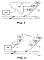
- the central evaluation device AWE communicates with metering points ZP1 ... ZP3, whereby communication connections are only established if necessary.
- this communication link includes transmission paths a public telephone network PSTN.
- the metering points and the central Evaluation device AWE are here with conventional telephone connections equipped that allow a connection to be established if required.
- the operator of the railways can of course also use a telephone network non-public or a telephone or data network maintained by himself use. In general, any communication network comes into question here, which one guarantees a need-based connection establishment based on mediation. In this way, the cabling effort compared to solutions is fixed switched point-to-point connections significantly reduced.
- the communication connection is between the metering points ZP1 ... ZP3 and the central evaluation device AR a radio connection. It is essential here that there is no communication own, constantly available radio channel is reserved, but that, as in the above shown wired case, a channel is assigned only when needed. In An area with a large number of field elements can thus have one or a few Channels all communications are handled because of the existing Bandwidth scarcity brings significant cost advantages. Especially in Areas of low traffic routes are those due to the establishment of a connection or the channel assignment due to time delays acceptable.
- the radio connection is preferably a mobile radio connection.
- the electronic connection boxes of metering points ZP1 ... ZP3 are in this Case integrated mobile devices that dial into a public mobile network allow.
- the data arrive at a base station via the radio interface BTS and from there to a mobile switching center MSC, which sends the data to a line Network PSTN relayed.
- the central evaluation device AWE is directly connected to the PSTN network.
- the communication link in this case includes both transmission paths of a wired and also of a radio-based communication network.
- By including one (Mobile) radio connection is - apart from the connection of the electronic junction boxes with the rail contacts - no wiring required.
- a metering point only then in the Communication network dials in if after the last registered axis pass a specified period of time has passed. This means a departure from the process, as it is hard-wired from known, with a central evaluation device Meter points knows. Meter readings are transmitted there on request through the evaluation device. In contrast, in the method according to the invention communication takes place only after the end of a train journey. So that will achieves that the central evaluation device on the one hand immediately on every traffic event informs, but only a communication link for the period of time that is absolutely necessary for the transmission of the counting result is.
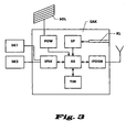
- Fig. 3 shows an embodiment of an electronic connection box EAK according to the invention in a schematic representation.
- the electronic junction box EAK is connected to rail contacts SK1 and SK2 via an interface IFSK.
- the signals picked up by the receiver coils of the rail contacts are fed to an evaluation circuit AS via this interface IFSK.
- the evaluation circuit AS has the task of driving the two rail contacts SK1 and SK2, generating counting pulses from the signals supplied via the rail contact interface IFSK and determining a counter reading therefrom.
- G. Hoffmann and H. Uebel with the title "New metering points (Zp 30) for axle counters", Signal + Draht 77 (1985) 4, pages 72-77.
- a second interface IFGSM provides the connection to the communication network
- the communication network is a public mobile radio network according to the GSM standard.
- the interface is therefore known as such GSM transceiver part executed.
- the communication network is a landline, for example, the IFGSM interface can be a simple X.25 interface, as is often the case in public data networks for packet-switched data communication used.
- the evaluation circuit AS is connected to a timer circuit TIM.
- This Timer circuit TIM is designed so that when one of the evaluation circuit is received AS supplied counting pulse a timer is started. The timer runs as long until the next count pulse is received and the timer is reset. Exceeds the timer has a predetermined value, e.g. B. 15 seconds, it is assumed that the end of the rail vehicle or the train set the rail contacts happened. The timer then issues a send command to cause that the determined meter reading is transmitted to the central evaluation device becomes.
- the time period after its elapse a send command is issued, not fixed once, but instead from the timer circuit after evaluating the chronological sequence of the previously received Count pulses set.
- the reasoning behind it is that it depends on the speed of the passing rail vehicle depends on when you fail to arrive of counting pulses with a very high probability can assume that no axes pass the rail contacts. For example, at the counting impulses for a fast moving train association at short intervals on each other. The timer circuit evaluates these time intervals and, for example, provides determined that the longest occurring interval does not exceed 1 second. From this size, the time period is then calculated, after which a Send command is issued. For example, the calculation can be done in a simple Multiplication by a fixed value, such as 5, exist. This means five seconds the send command is issued after the last registered axis pass becomes. With a slow train, on the other hand, with a train between two axles can pass several seconds, the calculated value will be correspondingly higher lie.
- the electronic junction box EAK relates to an advantageous embodiment the electrical energy required from a local power supply.
- this is designed as a rechargeable battery ACCU.
- a solar panel SOL is provided for loading the rechargeable battery.
- the electronic junction box EAK has a memory SP with input means KL. Your own address and address are stored in this memory can be stored in the central evaluation device.
- the addresses can be, for example are normal phone numbers.
- the input means KL can be used as Wire jumpers or, as indicated in Fig. 3, be designed as a card reader. With A card reader can be particularly easily integrated into the electronic Junction box EAK addresses entered. Such card readers are preferred also available in the central evaluation facilities to find the addresses of the to enter metering points arranged along the rail route. On the cards codes can also be stored, with the aid of which the data transmission can also be carried out can be backed up to any existing data backup measures.
- the central evaluation device in addition in regular time intervals establishes a connection to the metering points and meter readings queries. If the metering points are equipped with means for carrying out self-tests , they are preferably used as part of the regular meter reading queries initiated and their result transmitted to the evaluation device. In this way, defects in metering points can be made within the required disclosure period identify.
Landscapes
- Engineering & Computer Science (AREA)
- Mechanical Engineering (AREA)
- Automation & Control Theory (AREA)
- Mobile Radio Communication Systems (AREA)
- Train Traffic Observation, Control, And Security (AREA)
- Arrangements For Transmission Of Measured Signals (AREA)
Applications Claiming Priority (2)
| Application Number | Priority Date | Filing Date | Title |
|---|---|---|---|
| DE19836421 | 1998-08-12 | ||
| DE19836421A DE19836421A1 (de) | 1998-08-12 | 1998-08-12 | Verfahren zur Übermittlung eines von einem Zählpunkt ermittelten Zählerstands an eine zentrale Auswerteeinrichtung |
Publications (3)
| Publication Number | Publication Date |
|---|---|
| EP0979765A2 true EP0979765A2 (fr) | 2000-02-16 |
| EP0979765A3 EP0979765A3 (fr) | 2002-05-15 |
| EP0979765B1 EP0979765B1 (fr) | 2005-04-27 |
Family
ID=7877227
Family Applications (1)
| Application Number | Title | Priority Date | Filing Date |
|---|---|---|---|
| EP99440222A Expired - Lifetime EP0979765B1 (fr) | 1998-08-12 | 1999-08-12 | Procédé pour la transmission de la valeur de comptage d'un point de comptage à un dispositif central d'évaluation |
Country Status (4)
| Country | Link |
|---|---|
| EP (1) | EP0979765B1 (fr) |
| AT (1) | ATE294090T1 (fr) |
| DE (2) | DE19836421A1 (fr) |
| ES (1) | ES2238819T3 (fr) |
Cited By (3)
| Publication number | Priority date | Publication date | Assignee | Title |
|---|---|---|---|---|
| WO2010006926A1 (fr) * | 2008-07-15 | 2010-01-21 | Siemens Aktiengesellschaft | Procédé et dispositif pour faire fonctionner un équipement de sécurité ferroviaire |
| EP2218624A3 (fr) * | 2009-02-13 | 2011-03-09 | Siemens Aktiengesellschaft | Capteur de roue, installation de voie ferrée dotée d'au moins un capteur de roue ainsi que procédé de fonctionnement d'une installation de voie ferrée |
| EP2674345A3 (fr) * | 2012-06-11 | 2015-07-29 | Dirk Munder | Dispositif de détection d'états sur des tronçons de voie ferrée |
Families Citing this family (3)
| Publication number | Priority date | Publication date | Assignee | Title |
|---|---|---|---|---|
| DE102007038819B4 (de) * | 2007-08-16 | 2015-01-22 | Deutsches Zentrum für Luft- und Raumfahrt e.V. | Vorrichtung zur fahrzeugseitigen Gleisfrei- und/oder Gleisbesetztmeldung |
| ES2319062B1 (es) * | 2007-09-19 | 2010-02-03 | Lineas Y Cables, S.A. | Pedal ferroviario. |
| CN111376947A (zh) * | 2020-04-01 | 2020-07-07 | 北京永列科技有限公司 | 一种计轴系统及其无线通信方法 |
Family Cites Families (8)
| Publication number | Priority date | Publication date | Assignee | Title |
|---|---|---|---|---|
| DE2054748C3 (de) * | 1970-11-06 | 1979-05-10 | Standard Elektrik Lorenz Ag, 7000 Stuttgart | Einrichtung zum Auswerten von fahrtrichtungsabhängigen Achszählimpulsen in Eisenbahnsicherungsanlagen |
| DE3223327A1 (de) * | 1982-06-19 | 1983-12-22 | Licentia Patent-Verwaltungs-Gmbh, 6000 Frankfurt | Sichere gleisfreimeldeeinrichtung |
| DE3431171C2 (de) * | 1984-08-24 | 1986-11-27 | Standard Elektrik Lorenz Ag, 7000 Stuttgart | Gleisfreimeldeeinrichtung mit Achszählung |
| DE3445115A1 (de) * | 1984-12-11 | 1986-06-12 | Verkehrsbetriebe Peine-Salzgitter Gmbh, 3320 Salzgitter | Anordnung zur vereinfachung und verbesserung der zugfahrtsicherung |
| DE4223596A1 (de) * | 1992-07-17 | 1992-12-03 | Rutenbeck Wilhelm Gmbh & Co | Schaltungsanordnung zur telefonischen fernabfrage und fernsteuerung von schaltzustaenden und schaltfunktionen von elektrischen funktionsteilen |
| DE19504493A1 (de) * | 1995-02-12 | 1996-08-14 | Atw Umweltanalytik Gmbh | Verfahren und Vorrichtung zum drahtlosen Meßdatenaustausch |
| DE19523726A1 (de) * | 1995-06-23 | 1997-01-02 | Siemens Ag | Verfahren zur streckenseitigen Zugschlußerkennung im Eisenbahnwesen |
| DE19733765A1 (de) * | 1997-08-05 | 1999-02-11 | Alsthom Cge Alcatel | Verfahren zur Kommunikation zwischen einem im Bereich einer Schienenstrecke angeordneten Feldelement und einer zentralen Überwachungseinheit sowie Kommunikationssystem und Sendeempfangseinheit hierfür |
-
1998
- 1998-08-12 DE DE19836421A patent/DE19836421A1/de not_active Withdrawn
-
1999
- 1999-08-12 ES ES99440222T patent/ES2238819T3/es not_active Expired - Lifetime
- 1999-08-12 EP EP99440222A patent/EP0979765B1/fr not_active Expired - Lifetime
- 1999-08-12 AT AT99440222T patent/ATE294090T1/de not_active IP Right Cessation
- 1999-08-12 DE DE59911968T patent/DE59911968D1/de not_active Expired - Lifetime
Cited By (4)
| Publication number | Priority date | Publication date | Assignee | Title |
|---|---|---|---|---|
| WO2010006926A1 (fr) * | 2008-07-15 | 2010-01-21 | Siemens Aktiengesellschaft | Procédé et dispositif pour faire fonctionner un équipement de sécurité ferroviaire |
| US8540192B2 (en) | 2008-07-15 | 2013-09-24 | Siemens Aktiengesellschaft | Method and apparatus for operation of railroad protection installation |
| EP2218624A3 (fr) * | 2009-02-13 | 2011-03-09 | Siemens Aktiengesellschaft | Capteur de roue, installation de voie ferrée dotée d'au moins un capteur de roue ainsi que procédé de fonctionnement d'une installation de voie ferrée |
| EP2674345A3 (fr) * | 2012-06-11 | 2015-07-29 | Dirk Munder | Dispositif de détection d'états sur des tronçons de voie ferrée |
Also Published As
| Publication number | Publication date |
|---|---|
| EP0979765B1 (fr) | 2005-04-27 |
| DE59911968D1 (de) | 2005-06-02 |
| EP0979765A3 (fr) | 2002-05-15 |
| ES2238819T3 (es) | 2005-09-01 |
| DE19836421A1 (de) | 2000-02-17 |
| ATE294090T1 (de) | 2005-05-15 |
Similar Documents
| Publication | Publication Date | Title |
|---|---|---|
| EP0923061B1 (fr) | Procédé et dispositif pour l'affichage automatique du temps probable restant avant l'arrivée du véhicule suivant aux arrêts d'un transport publique | |
| DE19509696C2 (de) | Verfahren zur gegenseitigen Kontaktaufnahme zwischen Zügen und Einrichtung zur Durchführung des Verfahrens | |
| DE102008045050A1 (de) | Verfahren und Vorrichtung zur Zugbeeinflussung | |
| EP2307256A1 (fr) | Procédé et dispositif pour faire fonctionner un équipement de sécurité ferroviaire | |
| DE910551C (de) | Elektrisches Zugmeldesystem | |
| EP0979765B1 (fr) | Procédé pour la transmission de la valeur de comptage d'un point de comptage à un dispositif central d'évaluation | |
| EP2178733B1 (fr) | Procédé pour parvenir à intégrer sans grande complexité des composants de champ indépendants du trafic ferroviaire dans un système de commande | |
| WO2002002385A1 (fr) | Systeme d'extraction, de transmission et de sortie de donnees concernant la circulation | |
| EP1118185B1 (fr) | Systeme de communication pour radiocommande de voie | |
| DE19733765A1 (de) | Verfahren zur Kommunikation zwischen einem im Bereich einer Schienenstrecke angeordneten Feldelement und einer zentralen Überwachungseinheit sowie Kommunikationssystem und Sendeempfangseinheit hierfür | |
| EP0735381B1 (fr) | Méthode et système de communication pour transmission des données entre deux stations | |
| DE1588669A1 (de) | Schaltungsanordnung zur selektiven Eingabe von Steuerbefehlen in eine Vielzahl von Befehlsempfaengern | |
| DE4005354A1 (de) | Verfahren und einrichtung zur warnung von personen im gleisbereich ueber einen hochfrequenten nachrichtenkanal | |
| DE3445115A1 (de) | Anordnung zur vereinfachung und verbesserung der zugfahrtsicherung | |
| DE19957258A1 (de) | Verfahren zur Gleisfreimeldung mittels Achszählung | |
| WO2017045863A1 (fr) | Dispositif de communication et procédé d'échange automatisé d'informations dans une installation technique ferroviaire | |
| EP1396413B1 (fr) | Procédé pour commande auxiliaire d'éléments de voie | |
| WO1994020349A1 (fr) | Procede permettant de faire fonctionner une installation servant a compter les essieux et dispositif de mise en oeuvre dudit procede | |
| DE2247275C2 (de) | Anordnung bei eisenbahnanlagen mit linienfoermiger informationsuebertragung zwischen zug und strecke | |
| DE1455382C3 (de) | Schaltungsanordnung zum automatischen überwachen des Verkehrs von Unterpflaster- und Straßenbahnen | |
| EP1026062B1 (fr) | Procédé d'évaluation de signaux de contact des rails | |
| EP4696584A1 (fr) | Procédé de transmission et de vérification de données de direction de train | |
| EP1222100B1 (fr) | Procede et dispositif de securisation d'une section de voie a double sens de circulation | |
| DE1254174B (de) | Einrichtung in einem Fahrzeuggeraet fuer Anlagen zur linienfoermigen Zugbeeinflussung | |
| DE1449079C (de) | Einrichtung zur zentralen Standort überwachung der Fahrzeuge eines Verkehrs netzes, z B eines stadtischen Omnibus netzes |
Legal Events
| Date | Code | Title | Description |
|---|---|---|---|
| PUAI | Public reference made under article 153(3) epc to a published international application that has entered the european phase |
Free format text: ORIGINAL CODE: 0009012 |
|
| AK | Designated contracting states |
Kind code of ref document: A2 Designated state(s): AT BE CH CY DE DK ES FI FR GB GR IE IT LI LU MC NL PT SE |
|
| AX | Request for extension of the european patent |
Free format text: AL;LT;LV;MK;RO;SI |
|
| PUAL | Search report despatched |
Free format text: ORIGINAL CODE: 0009013 |
|
| AK | Designated contracting states |
Kind code of ref document: A3 Designated state(s): AT BE CH CY DE DK ES FI FR GB GR IE IT LI LU MC NL PT SE |
|
| AX | Request for extension of the european patent |
Free format text: AL;LT;LV;MK;RO;SI |
|
| RIC1 | Information provided on ipc code assigned before grant |
Free format text: 7B 61L 27/04 A, 7B 61L 1/16 B, 7B 61L 3/12 B |
|
| 17P | Request for examination filed |
Effective date: 20020409 |
|
| AKX | Designation fees paid |
Designated state(s): AT BE CH CY DE DK ES FI FR GB GR IE IT LI LU MC NL PT SE |
|
| GRAP | Despatch of communication of intention to grant a patent |
Free format text: ORIGINAL CODE: EPIDOSNIGR1 |
|
| GRAS | Grant fee paid |
Free format text: ORIGINAL CODE: EPIDOSNIGR3 |
|
| GRAA | (expected) grant |
Free format text: ORIGINAL CODE: 0009210 |
|
| AK | Designated contracting states |
Kind code of ref document: B1 Designated state(s): AT BE CH CY DE DK ES FI FR GB GR IE IT LI LU MC NL PT SE |
|
| PG25 | Lapsed in a contracting state [announced via postgrant information from national office to epo] |
Ref country code: NL Free format text: LAPSE BECAUSE OF FAILURE TO SUBMIT A TRANSLATION OF THE DESCRIPTION OR TO PAY THE FEE WITHIN THE PRESCRIBED TIME-LIMIT Effective date: 20050427 Ref country code: IE Free format text: LAPSE BECAUSE OF FAILURE TO SUBMIT A TRANSLATION OF THE DESCRIPTION OR TO PAY THE FEE WITHIN THE PRESCRIBED TIME-LIMIT Effective date: 20050427 Ref country code: FI Free format text: LAPSE BECAUSE OF FAILURE TO SUBMIT A TRANSLATION OF THE DESCRIPTION OR TO PAY THE FEE WITHIN THE PRESCRIBED TIME-LIMIT Effective date: 20050427 |
|
| REG | Reference to a national code |
Ref country code: GB Ref legal event code: FG4D Free format text: NOT ENGLISH |
|
| REG | Reference to a national code |
Ref country code: CH Ref legal event code: EP |
|
| REG | Reference to a national code |
Ref country code: IE Ref legal event code: FG4D Free format text: LANGUAGE OF EP DOCUMENT: GERMAN |
|
| GBT | Gb: translation of ep patent filed (gb section 77(6)(a)/1977) |
Effective date: 20050504 |
|
| REF | Corresponds to: |
Ref document number: 59911968 Country of ref document: DE Date of ref document: 20050602 Kind code of ref document: P |
|
| PG25 | Lapsed in a contracting state [announced via postgrant information from national office to epo] |
Ref country code: SE Free format text: LAPSE BECAUSE OF FAILURE TO SUBMIT A TRANSLATION OF THE DESCRIPTION OR TO PAY THE FEE WITHIN THE PRESCRIBED TIME-LIMIT Effective date: 20050727 Ref country code: GR Free format text: LAPSE BECAUSE OF FAILURE TO SUBMIT A TRANSLATION OF THE DESCRIPTION OR TO PAY THE FEE WITHIN THE PRESCRIBED TIME-LIMIT Effective date: 20050727 Ref country code: DK Free format text: LAPSE BECAUSE OF FAILURE TO SUBMIT A TRANSLATION OF THE DESCRIPTION OR TO PAY THE FEE WITHIN THE PRESCRIBED TIME-LIMIT Effective date: 20050727 |
|
| PG25 | Lapsed in a contracting state [announced via postgrant information from national office to epo] |
Ref country code: LU Free format text: LAPSE BECAUSE OF NON-PAYMENT OF DUE FEES Effective date: 20050812 Ref country code: CY Free format text: LAPSE BECAUSE OF FAILURE TO SUBMIT A TRANSLATION OF THE DESCRIPTION OR TO PAY THE FEE WITHIN THE PRESCRIBED TIME-LIMIT Effective date: 20050812 Ref country code: AT Free format text: LAPSE BECAUSE OF NON-PAYMENT OF DUE FEES Effective date: 20050812 |
|
| PG25 | Lapsed in a contracting state [announced via postgrant information from national office to epo] |
Ref country code: MC Free format text: LAPSE BECAUSE OF NON-PAYMENT OF DUE FEES Effective date: 20050831 Ref country code: LI Free format text: LAPSE BECAUSE OF NON-PAYMENT OF DUE FEES Effective date: 20050831 Ref country code: CH Free format text: LAPSE BECAUSE OF NON-PAYMENT OF DUE FEES Effective date: 20050831 Ref country code: BE Free format text: LAPSE BECAUSE OF NON-PAYMENT OF DUE FEES Effective date: 20050831 |
|
| REG | Reference to a national code |
Ref country code: ES Ref legal event code: FG2A Ref document number: 2238819 Country of ref document: ES Kind code of ref document: T3 |
|
| PG25 | Lapsed in a contracting state [announced via postgrant information from national office to epo] |
Ref country code: PT Free format text: LAPSE BECAUSE OF FAILURE TO SUBMIT A TRANSLATION OF THE DESCRIPTION OR TO PAY THE FEE WITHIN THE PRESCRIBED TIME-LIMIT Effective date: 20051010 |
|
| NLV1 | Nl: lapsed or annulled due to failure to fulfill the requirements of art. 29p and 29m of the patents act | ||
| REG | Reference to a national code |
Ref country code: IE Ref legal event code: FD4D |
|
| ET | Fr: translation filed | ||
| PLBE | No opposition filed within time limit |
Free format text: ORIGINAL CODE: 0009261 |
|
| STAA | Information on the status of an ep patent application or granted ep patent |
Free format text: STATUS: NO OPPOSITION FILED WITHIN TIME LIMIT |
|
| REG | Reference to a national code |
Ref country code: CH Ref legal event code: PL |
|
| 26N | No opposition filed |
Effective date: 20060130 |
|
| BERE | Be: lapsed |
Owner name: ALCATEL Effective date: 20050831 |
|
| REG | Reference to a national code |
Ref country code: FR Ref legal event code: PLFP Year of fee payment: 18 |
|
| REG | Reference to a national code |
Ref country code: FR Ref legal event code: PLFP Year of fee payment: 19 |
|
| REG | Reference to a national code |
Ref country code: FR Ref legal event code: PLFP Year of fee payment: 20 |
|
| PGFP | Annual fee paid to national office [announced via postgrant information from national office to epo] |
Ref country code: DE Payment date: 20180821 Year of fee payment: 20 Ref country code: IT Payment date: 20180821 Year of fee payment: 20 Ref country code: FR Payment date: 20180828 Year of fee payment: 20 Ref country code: ES Payment date: 20180903 Year of fee payment: 20 |
|
| PGFP | Annual fee paid to national office [announced via postgrant information from national office to epo] |
Ref country code: GB Payment date: 20180820 Year of fee payment: 20 |
|
| REG | Reference to a national code |
Ref country code: DE Ref legal event code: R071 Ref document number: 59911968 Country of ref document: DE |
|
| REG | Reference to a national code |
Ref country code: GB Ref legal event code: PE20 Expiry date: 20190811 |
|
| PG25 | Lapsed in a contracting state [announced via postgrant information from national office to epo] |
Ref country code: GB Free format text: LAPSE BECAUSE OF EXPIRATION OF PROTECTION Effective date: 20190811 |
|
| REG | Reference to a national code |
Ref country code: ES Ref legal event code: FD2A Effective date: 20201110 |
|
| PG25 | Lapsed in a contracting state [announced via postgrant information from national office to epo] |
Ref country code: ES Free format text: LAPSE BECAUSE OF EXPIRATION OF PROTECTION Effective date: 20190813 |