EP0979961B1 - Dispositif d'etancheite pour machines tournantes - Google Patents
Dispositif d'etancheite pour machines tournantes Download PDFInfo
- Publication number
- EP0979961B1 EP0979961B1 EP99906454A EP99906454A EP0979961B1 EP 0979961 B1 EP0979961 B1 EP 0979961B1 EP 99906454 A EP99906454 A EP 99906454A EP 99906454 A EP99906454 A EP 99906454A EP 0979961 B1 EP0979961 B1 EP 0979961B1
- Authority
- EP
- European Patent Office
- Prior art keywords
- seal
- plate
- seal plate
- groove
- spring
- Prior art date
- Legal status (The legal status is an assumption and is not a legal conclusion. Google has not performed a legal analysis and makes no representation as to the accuracy of the status listed.)
- Expired - Lifetime
Links
- 239000012530 fluid Substances 0.000 claims description 11
- 238000007789 sealing Methods 0.000 claims description 9
- 238000001816 cooling Methods 0.000 description 12
- 238000005299 abrasion Methods 0.000 description 4
- 230000006866 deterioration Effects 0.000 description 3
- 239000012809 cooling fluid Substances 0.000 description 2
- 238000013016 damping Methods 0.000 description 2
- 230000000694 effects Effects 0.000 description 2
- 239000002184 metal Substances 0.000 description 2
- 238000005219 brazing Methods 0.000 description 1
- 230000001419 dependent effect Effects 0.000 description 1
- 230000002265 prevention Effects 0.000 description 1
- 230000001629 suppression Effects 0.000 description 1
- 238000003466 welding Methods 0.000 description 1
Images



Classifications
-
- F—MECHANICAL ENGINEERING; LIGHTING; HEATING; WEAPONS; BLASTING
- F16—ENGINEERING ELEMENTS AND UNITS; GENERAL MEASURES FOR PRODUCING AND MAINTAINING EFFECTIVE FUNCTIONING OF MACHINES OR INSTALLATIONS; THERMAL INSULATION IN GENERAL
- F16J—PISTONS; CYLINDERS; SEALINGS
- F16J9/00—Piston-rings, e.g. non-metallic piston-rings, seats therefor; Ring sealings of similar construction
- F16J9/12—Details
- F16J9/14—Joint-closures
-
- F—MECHANICAL ENGINEERING; LIGHTING; HEATING; WEAPONS; BLASTING
- F01—MACHINES OR ENGINES IN GENERAL; ENGINE PLANTS IN GENERAL; STEAM ENGINES
- F01D—NON-POSITIVE DISPLACEMENT MACHINES OR ENGINES, e.g. STEAM TURBINES
- F01D11/00—Preventing or minimising internal leakage of working-fluid, e.g. between stages
- F01D11/005—Sealing means between non relatively rotating elements
-
- F—MECHANICAL ENGINEERING; LIGHTING; HEATING; WEAPONS; BLASTING
- F16—ENGINEERING ELEMENTS AND UNITS; GENERAL MEASURES FOR PRODUCING AND MAINTAINING EFFECTIVE FUNCTIONING OF MACHINES OR INSTALLATIONS; THERMAL INSULATION IN GENERAL
- F16J—PISTONS; CYLINDERS; SEALINGS
- F16J15/00—Sealings
- F16J15/02—Sealings between relatively-stationary surfaces
- F16J15/06—Sealings between relatively-stationary surfaces with solid packing compressed between sealing surfaces
- F16J15/08—Sealings between relatively-stationary surfaces with solid packing compressed between sealing surfaces with exclusively metal packing
- F16J15/0887—Sealings between relatively-stationary surfaces with solid packing compressed between sealing surfaces with exclusively metal packing the sealing effect being obtained by elastic deformation of the packing
Definitions
- the present invention relates to a seal device for effecting a gas seal in a rotating machine of a gas turbine and the like in which a high temperature gas flows.
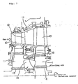
- Fig. 7 is a cross sectional view of a related portion of a prior art gas turbine.
- numeral 1 designates a turbine disc, which is fixed to a rotating shaft.
- Numeral 10 designates a moving blade, which is implanted in an outer circumferential portion of the turbine disc 1 and numeral 11 designates a stationary blade.
- a cooling air cavity 14 is formed between the turbine discs 1,1 of mutually adjacent stages and a labyrinth seal 15 is provided on an inner circumferential surface of the stationary blade 11 for effecting a gas seal between a gas path 12 and the cooling air cavity 14.
- Numeral 13 designates a cooling air passage for leading therethrough a cooling fluid into the cooling air cavity 14.
- Numeral 2 designates a seal plate provided in the turbine discs 1,1 on an inner side of the labyrinth seal 15.
- the seal plate 2 is a thin metal ring, which is divided into plural pieces (four pieces in this example) in the circumferential direction.
- a divided part 2c so divided has its upper and lower divided surfaces formed in stepped shapes, respectively, so as to be gas tight when they are mated with each other.
- the seal plate 2 is assembled into grooves 1a (see Fig. 2) provided in the mutually adjacent turbine discs 1,1.
- the seal plate 2 While in operation, the seal plate 2 is pressed against outer circumferential wall surfaces 1b of the grooves 1a by the centrifugal force of the seal plate 2 itself due to a high speed rotation of the turbine discs 1,1, so that the cooling fluid is prevented from leaking into the gas path 12 side by a differential pressure between the gas path 12 and the cooling air cavity 14.
- the seal plate 2 is divided into plural pieces in the circumferential direction and so the fluid intrudes easily into the divided part 2c. Also, as the seal plate 2 is pressed against the outer circumferential wall surfaces 1b of the grooves 1a of the turbine discs 1,1 only by the own centrifugal force, that pressing force is small and self-induced vibration of the seal plate 2 is liable to occur when the fluid so intrudes. Thus, in the prior art-seal structure as mentioned above, there is often caused abrasion or thinning of the seal plate 2 by said self-induced vibration, which results in the problem of occurrence of deterioration of the sealing performance.
- US-A-5 865 600 discloses a rotating machine seal device to be inserted into a groove provided in a portion of a disc that is to be driven rotationally, wherein the seal device is for sealing fluid between a fluid passage on an outer circumferential side of the groove and a fluid passage on an inner circumferential side of the groove.
- This known seal device is constructed of two belt-like elements bent in a warped arc and integrally joined by spot welding or brazing at central portions thereof along a central circumferential portion. This seal device operates in that it is held in close contact with both opposite inner surfaces of the groove in the disc portion due to the spring effect of the two belt-like elements.
- the present invention provides a rotating machine seal device according to claim 1.
- Preferred embodiments are defined in the dependent claims.
- the seal plate receives not only its own centrifugal force but also the spring force and the centrifugal force of the spring plate to be pressed against the seal surfaces of the grooves by the combined force thereof, thus the seal of the fluid on the seal surfaces can be effected securely.
- said combined force is strong enough for pressing the seal plate against the seal surfaces of the grooves of the disc portion and even if the fluid intrudes into the divided part of the seal plate, the self-induced vibration is reduced without occurrence of such a self-induced vibration as in the prior art case, which results in the prevention of occurrence of abrasion or thinning of the seal plate due to the self-induced vibration.
- the present invention provides a rotating machine seal device wherein said seal plate is made by a plurality of seal plates lapped one on another to be inserted into said groove and said spring plate is disposed on an inner circumferential side of said plurality of seal plates.
- the seal plate is made by the plurality of seal plates lapped one on another, thereby the centrifugal force of the seal plate itself increases and the seal plate can be pressed against the seal surfaces of the grooves by a larger pressing force, which results in the further enhancement of the sealing performance. Also, by the effect of frictions on the contact surfaces of the plurality of seal plates, the self-induced vibration can be reduced further.
- the present invention also provides a rotating machine seal device wherein said seal plate is divided into plural pieces along a circumferential direction thereof and one piece of said seal plate in a divided part has a projection portion formed thereon and the other piece thereof in said divided part has a groove portion formed therein so that said projection portion is inserted into said groove portion with a predetermined space remaining in the circumferential direction of said seal plate.
- the plural pieces of the divided seal plate are connected to each other in the circumferential direction with the projection portions and the groove portions of the respective seal plate pieces being mated with each other with the space therebetween, thereby the assembling work of the seal plate can be facilitated and the circumferential directional stress of the seal plate can be reduced.
- Figs. 1 to 3 show a structure of the seal plate 2 and a fitting mode thereof in a seal device of the first embodiment according to the present invention.
- the seal plate 2 is a thin metal ring, which is divided into plural pieces in a circumferential direction thereof.
- a divided part 21 so divided has its upper and lower divided surfaces formed in stepped shapes, respectively, so as to be gas tight when they are mated with each other.
- a spring plate 3 formed in a wave shape.
- the spring plate 3 is divided into plural pieces in a circumferential direction thereof and has a fitting hole 3a bored at an arbitrary position thereof, so that a pin 4 provided projecting from an inner circumferential surface of the seal plate 2 fits in the fitting hole 3a to prevent deviation of the spring plate 3 relative to the seal plate 2 in the circumferential direction.
- Fig. 2 shows a state where the seal plate 2 and the spring plate 3 are assembled into the turbine discs 1,1 of mutually adjacent stages.
- Numeral 1a designates grooves provided in the turbine discs 1,1 on an inner side of the labyrinth seal 15 (see Fig. 7) and the seal plate 2 is assembled into the grooves 1a while being pressed from its inner circumferential side by a spring force of the spring plate 3.
- the seal plate 2 is fitted in the grooves 1a firmly by the spring force of the spring plate 3 and the centrifugal forces as mentioned above, thereby the seal plate 2 and the spring plate 3 are prevented from moving in the circumferential direction and there occurs no such a large self-induced vibration as in the prior art case even if the gas or cooling air intrudes in the divided part 21 of the seal plate 2. Further, a relative movement of the seal plate 2 and the spring plate 3 is prevented by the pin 4 and there occurs no case of deviation between both of them.
- Figs. 4 and 5 show a seal device of a second embodiment according to the present invention, wherein Fig. 4 is a cross sectional partial front view of a seal plate and a spring plate and Fig. 5 is a cross sectional view showing a fitting state of the seal device.
- two seal plates 2, 2' (seal plates of more than two are also applicable) are provided being lapped one on another in a radial direction thereof. That is, in Figs. 4 and 5, numeral 2 designates an outer seal plate and numeral 2' designates an inner seal plate. Both the seal plates 2, 2', being mutually lapped in the radial direction as shown in Fig. 5, are inserted into the grooves 1a of the turbine discs 1,1 and a spring plate 3 which is substantially same as that of the first embodiment is fitted on the inner circumferential surface of the inner seal plate 2'.
- Both said outer seal plate 2 and inner seal plate 2' are divided into plural pieces in the circumferential direction.
- Numeral 22 designates a divided part of the outer seal plate 2
- numeral 23 designates a divided part of the inner seal plate 2'.
- the outer seal plate 2 has a pin 4 provided projecting from its inner circumferential surface at an arbitrary position thereof, and the inner seal plate 2' and the spring plate 3 have fitting holes 2a and 3a, respectively.
- the two seal plates are provided being lapped one on another, thereby the centrifugal force of the two seal plates 2, 2' increases to enhance the sealing performance.
- frictions on the contact surface of the outer seal plate 2 and the inner seal plate 2' provide a damping action of the self-induced vibration, thereby the self-induced vibration is reduced further than in the first embodiment.
- Fig. 6 shows a seal plate used in a seal device of a third embodiment according to the present invention, wherein Fig. 6(A) is a partial front view of the seal plate before it is assembled and Fig. 6(B) is a same view after the seal plate is assembled.
- the groove portion 6 is formed with its circumferential directional width being made larger than a circumferential directional width of the projection portion 5 and, as shown in Fig. 6(B), when the seal plate including the pieces 2d, 2d' whose gas tight surfaces are lapped one on another is fitted into the grooves 1a of the turbine discs 1,1 (see Fig. 2), a small relative movement between the seal plate pieces in the circumferential direction is allowable so as to facilitate the assembling work as well as a circumferential directional stress of the seal plate caused at the time of a high temperature high load operation is reduced.
- the plurality of the seal plates are lapped one on another, thereby the centrifugal force of the seal plates increases to increase the pressing force onto the seal surfaces, which results in the further enhancement of the sealing performance as well as in the further suppression of the self-induced vibration by the damping action due to mutual contact of the seal plates.
Landscapes
- Engineering & Computer Science (AREA)
- General Engineering & Computer Science (AREA)
- Mechanical Engineering (AREA)
- Turbine Rotor Nozzle Sealing (AREA)
- Gasket Seals (AREA)
- Structures Of Non-Positive Displacement Pumps (AREA)
Claims (6)
- Dispositif d'étanchéité pour machines tournantes devant être introduit à l'intérieur d'une gorge (1a) aménagée dans une partie de disque (1) qui doit être entraînée en rotation, dans lequel ledit dispositif d'étanchéité est destiné à rendre étanche un fluide entre un passage de fluide (12) situé sur un côté de circonférence externe de ladite gorge (1a) et un passage de fluide (14) situé sur un côté de circonférence interne de ladite gorge (1a), ledit dispositif d'étanchéité comprenant :une plaque d'étanchéité (2), dans laquelle ladite plaque d'étanchéité (2) est divisée en une pluralité de pièces le long d'une direction de circonférence de celle-ci ; etune plaque de ressort (3), caractérisée en ce que ladite plaque de ressort n'est pas incorporée à ladite plaque d'étanchéité et est disposée sur un côté de circonférence interne de ladite plaque d'étanchéité (2) de telle sorte qu'une force de ressort de ladite plaque de ressort (3) pousse ladite plaque d'étanchéité (2) contre une surface d'étanchéité (1b) de ladite gorge (1a) lorsque la plaque d'étanchéité (2) est introduite à l'intérieur de ladite gorge (1a).
- Dispositif d'étanchéité pour machines tournantes selon la revendication 1, dans lequel ladite plaque d'étanchéité se compose d'une pluralité de plaques d'étanchéité (2, 2') en recouvrement les unes sur les autres lorsqu'elles sont introduites à l'intérieur de ladite gorge (1a) et ladite plaque de ressort (3) est disposée sur un côté de circonférence interne de ladite pluralité de plaques d'étanchéité (2, 2').
- Dispositif d'étanchéité pour machines tournantes selon la revendication 1 ou la revendication 2, dans lequel ladite plaque de ressort (3) a une forme ondulée.
- Dispositif d'étanchéité pour machines tournantes selon l'une quelconque des revendications 1 à 3, dans lequel ladite plaque d'étanchéité (2) comprend un goujon (4) en saillie à partir d'une surface de circonférence interne et ladite plaque de ressort (3) comprend un trou d'ajustement (3a) qui s'ajuste sur ledit goujon (4).
- Dispositif d'étanchéité pour machines tournantes selon l'une quelconque des revendications 1 à 4, dans lequel ladite plaque de ressort (3) se compose d'une pluralité de pièces de circonférence.
- Dispositif d'étanchéité pour machines tournantes selon l'une quelconque des revendications 1 à 4, dans lequel ladite plaque d'étanchéité est divisée en une pluralité de pièces le long d'une direction de circonférence de celle-ci et une pièce (2d') de ladite plaque d'étanchéité d'une partie divisée comprend une partie en saillie (5) formée sur celle-ci et l'autre pièce (2d) de celle-ci de ladite partie divisée comprend une partie de gorge (6) formée en elle de telle sorte que ladite partie en saillie (5) est introduite à l'intérieur de ladite partie de gorge (6), un espace prédéterminé restant dans la direction de la circonférence de ladite plaque d'étanchéité.
Applications Claiming Priority (3)
| Application Number | Priority Date | Filing Date | Title |
|---|---|---|---|
| JP04944198A JP3643692B2 (ja) | 1998-03-02 | 1998-03-02 | 回転機械のシール装置 |
| JP4944198 | 1998-03-02 | ||
| PCT/JP1999/000769 WO1999045297A1 (fr) | 1998-03-02 | 1999-02-22 | Dispositif d'etancheite pour machines tournantes |
Publications (3)
| Publication Number | Publication Date |
|---|---|
| EP0979961A1 EP0979961A1 (fr) | 2000-02-16 |
| EP0979961A4 EP0979961A4 (fr) | 2004-09-08 |
| EP0979961B1 true EP0979961B1 (fr) | 2006-05-03 |
Family
ID=12831218
Family Applications (1)
| Application Number | Title | Priority Date | Filing Date |
|---|---|---|---|
| EP99906454A Expired - Lifetime EP0979961B1 (fr) | 1998-03-02 | 1999-02-22 | Dispositif d'etancheite pour machines tournantes |
Country Status (6)
| Country | Link |
|---|---|
| US (1) | US6315301B1 (fr) |
| EP (1) | EP0979961B1 (fr) |
| JP (1) | JP3643692B2 (fr) |
| CA (1) | CA2287509C (fr) |
| DE (1) | DE69931113T2 (fr) |
| WO (1) | WO1999045297A1 (fr) |
Families Citing this family (47)
| Publication number | Priority date | Publication date | Assignee | Title |
|---|---|---|---|---|
| DE60102217T2 (de) * | 2001-05-30 | 2005-01-13 | Techspace Aero, Milmort | Dichtende Verbindungsplatte |
| US6612809B2 (en) * | 2001-11-28 | 2003-09-02 | General Electric Company | Thermally compliant discourager seal |
| US6733234B2 (en) * | 2002-09-13 | 2004-05-11 | Siemens Westinghouse Power Corporation | Biased wear resistant turbine seal assembly |
| US7562880B2 (en) * | 2004-02-09 | 2009-07-21 | Siemens Energy, Inc. | Seal usable between thermally movable components |
| US7234918B2 (en) * | 2004-12-16 | 2007-06-26 | Siemens Power Generation, Inc. | Gap control system for turbine engines |
| JP4822716B2 (ja) * | 2005-02-07 | 2011-11-24 | 三菱重工業株式会社 | シール構造を備えたガスタービン |
| US7788932B2 (en) | 2005-08-23 | 2010-09-07 | Mitsubishi Heavy Industries, Ltd. | Seal structure for gas turbine combustor |
| US7581931B2 (en) * | 2006-10-13 | 2009-09-01 | Siemens Energy, Inc. | Gas turbine belly band seal anti-rotation structure |
| US20090108538A1 (en) * | 2007-10-24 | 2009-04-30 | Freudenberg-Nok General Partnership | Two-Component Seal With Integral Locking Feature To Prevent Relative Rotation |
| US20090191050A1 (en) * | 2008-01-24 | 2009-07-30 | Siemens Power Generation, Inc. | Sealing band having bendable tang with anti-rotation in a turbine and associated methods |
| US8821114B2 (en) | 2010-06-04 | 2014-09-02 | Siemens Energy, Inc. | Gas turbine engine sealing structure |
| US8602737B2 (en) | 2010-06-25 | 2013-12-10 | General Electric Company | Sealing device |
| JP5493233B2 (ja) * | 2010-11-19 | 2014-05-14 | イーグル工業株式会社 | シール装置 |
| JP5631182B2 (ja) * | 2010-12-03 | 2014-11-26 | 三菱重工業株式会社 | ガスタービンのシール構造 |
| US9200527B2 (en) * | 2011-01-04 | 2015-12-01 | General Electric Company | Systems, methods, and apparatus for a turbine interstage rim seal |
| JP5769469B2 (ja) * | 2011-03-30 | 2015-08-26 | 三菱重工業株式会社 | シール構造 |
| JP5134703B2 (ja) * | 2011-04-27 | 2013-01-30 | 三菱重工業株式会社 | シール構造を備えたガスタービン |
| GB201109143D0 (en) * | 2011-06-01 | 2011-07-13 | Rolls Royce Plc | Flap seal spring and sealing apparatus |
| US8956120B2 (en) * | 2011-09-08 | 2015-02-17 | General Electric Company | Non-continuous ring seal |
| US9017015B2 (en) * | 2011-10-27 | 2015-04-28 | General Electric Company | Turbomachine including an inner-to-outer turbine casing seal assembly and method |
| JP5785056B2 (ja) * | 2011-11-08 | 2015-09-24 | 三菱日立パワーシステムズ株式会社 | ガスタービン |
| US8570505B2 (en) | 2012-03-06 | 2013-10-29 | Siemens Energy, Inc. | One-dimensional coherent fiber array for inspecting components in a gas turbine engine |
| US9206705B2 (en) * | 2012-03-07 | 2015-12-08 | Mitsubishi Hitachi Power Systems, Ltd. | Sealing device and gas turbine having the same |
| CN104204416B (zh) * | 2012-03-21 | 2017-09-26 | 通用电器技术有限公司 | 密封条及用于设计密封条的方法 |
| US9181810B2 (en) | 2012-04-16 | 2015-11-10 | General Electric Company | System and method for covering a blade mounting region of turbine blades |
| US9366151B2 (en) | 2012-05-07 | 2016-06-14 | General Electric Company | System and method for covering a blade mounting region of turbine blades |
| US9334738B2 (en) * | 2012-10-23 | 2016-05-10 | Siemens Aktiengesellschaft | Gas turbine including belly band seal anti-rotation device |
| US9347322B2 (en) | 2012-11-01 | 2016-05-24 | Siemens Aktiengesellschaft | Gas turbine including belly band seal anti-rotation device |
| US9200519B2 (en) * | 2012-11-01 | 2015-12-01 | Siemens Aktiengesellschaft | Belly band seal with underlapping ends |
| US9291065B2 (en) | 2013-03-08 | 2016-03-22 | Siemens Aktiengesellschaft | Gas turbine including bellyband seal anti-rotation device |
| US10208612B2 (en) * | 2013-03-08 | 2019-02-19 | Siemens Energy, Inc. | Gas turbine sealing band arrangement having an underlap seal |
| US9808889B2 (en) | 2014-01-15 | 2017-11-07 | Siemens Energy, Inc. | Gas turbine including sealing band and anti-rotation device |
| US9790863B2 (en) | 2013-04-05 | 2017-10-17 | Honeywell International Inc. | Fluid transfer seal assemblies, fluid transfer systems, and methods for transferring process fluid between stationary and rotating components using the same |
| US9399926B2 (en) * | 2013-08-23 | 2016-07-26 | Siemens Energy, Inc. | Belly band seal with circumferential spacer |
| US9759081B2 (en) * | 2013-10-08 | 2017-09-12 | General Electric Company | Method and system to facilitate sealing in gas turbines |
| FR3013766B1 (fr) * | 2013-11-25 | 2017-11-10 | Snecma | Turbomachine comprenant un fourreau d'arbre et tube de fourreau associe |
| EP2907977A1 (fr) * | 2014-02-14 | 2015-08-19 | Siemens Aktiengesellschaft | Composant pouvant être alimenté par un gaz chaud pour une turbine à gaz et système d'étanchéité doté d'un tel composant |
| US9631507B2 (en) * | 2014-07-14 | 2017-04-25 | Siemens Energy, Inc. | Gas turbine sealing band arrangement having a locking pin |
| CN104196636B (zh) * | 2014-07-31 | 2017-12-01 | 北京华清燃气轮机与煤气化联合循环工程技术有限公司 | 具有密封结构的燃气轮机 |
| DE102016215983A1 (de) | 2016-08-25 | 2018-03-01 | Siemens Aktiengesellschaft | Rotor mit geteiltem Dichtungsring |
| KR101877170B1 (ko) * | 2017-04-11 | 2018-08-07 | 두산중공업 주식회사 | 로터 디스크 실링장치와 이를 구비하는 로터 조립체 및 가스터빈 |
| EP3409898B1 (fr) | 2017-06-02 | 2020-05-13 | General Electric Technology GmbH | Joints de bande ventrale et procédé |
| DE102018204521A1 (de) * | 2018-03-23 | 2019-09-26 | MTU Aero Engines AG | Turbomaschinenbauteilanordnung |
| KR102821442B1 (ko) * | 2022-11-23 | 2025-06-16 | 두산에너빌리티 주식회사 | 터빈 베인 플랫폼 씰링 어셈블리, 이를 포함하는 터빈 베인 및 가스 터빈 |
| KR102868006B1 (ko) | 2022-12-09 | 2025-10-01 | 두산에너빌리티 주식회사 | 씰조립체를 구비하는 터빈 베인, 터빈 및 이를 포함하는 터보 머신 |
| KR102791366B1 (ko) | 2022-12-12 | 2025-04-07 | 두산에너빌리티 주식회사 | 터빈 베인 플랫폼 씰링 어셈블리, 이를 포함하는 터빈 베인 및 가스 터빈 |
| KR102612564B1 (ko) * | 2023-07-14 | 2023-12-11 | 한국중부발전(주) | 가스 터빈 |
Family Cites Families (12)
| Publication number | Priority date | Publication date | Assignee | Title |
|---|---|---|---|---|
| US1353082A (en) * | 1920-06-11 | 1920-09-14 | Frank K Stehle | Piston-ring |
| US2638390A (en) * | 1950-08-02 | 1953-05-12 | Johannes E Neeme | Piston and ring |
| US4537024A (en) * | 1979-04-23 | 1985-08-27 | Solar Turbines, Incorporated | Turbine engines |
| US4251083A (en) * | 1979-05-15 | 1981-02-17 | Adriel Montes | Piston ring with tongue and groove joint |
| JPS5896105A (ja) | 1981-12-03 | 1983-06-08 | Hitachi Ltd | スペ−サ先端空気漏洩防止ロ−タ |
| US5104287A (en) | 1989-09-08 | 1992-04-14 | General Electric Company | Blade tip clearance control apparatus for a gas turbine engine |
| US5221096A (en) * | 1990-10-19 | 1993-06-22 | Allied-Signal Inc. | Stator and multiple piece seal |
| JP2941698B2 (ja) | 1995-11-10 | 1999-08-25 | 三菱重工業株式会社 | ガスタービンロータ |
| JPH09242505A (ja) | 1996-03-11 | 1997-09-16 | Hitachi Ltd | タービン構造 |
| JPH102203A (ja) * | 1996-06-17 | 1998-01-06 | Mitsubishi Heavy Ind Ltd | ガスタービン冷却静翼 |
| JP3141804B2 (ja) | 1997-01-08 | 2001-03-07 | ダイキン工業株式会社 | 空気調和機 |
| FR2758856B1 (fr) * | 1997-01-30 | 1999-02-26 | Snecma | Joint d'etancheite a plaquettes empilees glissant dans des fentes de reception |
-
1998
- 1998-03-02 JP JP04944198A patent/JP3643692B2/ja not_active Expired - Lifetime
-
1999
- 1999-02-22 US US09/423,003 patent/US6315301B1/en not_active Expired - Lifetime
- 1999-02-22 WO PCT/JP1999/000769 patent/WO1999045297A1/fr not_active Ceased
- 1999-02-22 EP EP99906454A patent/EP0979961B1/fr not_active Expired - Lifetime
- 1999-02-22 DE DE69931113T patent/DE69931113T2/de not_active Expired - Lifetime
- 1999-02-22 CA CA002287509A patent/CA2287509C/fr not_active Expired - Lifetime
Also Published As
| Publication number | Publication date |
|---|---|
| CA2287509A1 (fr) | 1999-09-10 |
| DE69931113D1 (de) | 2006-06-08 |
| DE69931113T2 (de) | 2006-11-30 |
| JP3643692B2 (ja) | 2005-04-27 |
| EP0979961A4 (fr) | 2004-09-08 |
| JPH11247999A (ja) | 1999-09-14 |
| EP0979961A1 (fr) | 2000-02-16 |
| US6315301B1 (en) | 2001-11-13 |
| WO1999045297A1 (fr) | 1999-09-10 |
| CA2287509C (fr) | 2003-11-11 |
Similar Documents
| Publication | Publication Date | Title |
|---|---|---|
| US6315301B1 (en) | Seal apparatus for rotary machines | |
| EP0894947B1 (fr) | Joint inter-étages pour turbines à gaz | |
| US5865600A (en) | Gas turbine rotor | |
| US11859498B2 (en) | Labyrinth sealing device | |
| EP0833039B1 (fr) | Plaque d'étanchéité pour moteur à turbine | |
| EP1479952B1 (fr) | Dispositif d'étanchéité pour axe | |
| EP0717169B1 (fr) | Dispositif d'étanchéité et d'amortissement des vibrations pour la plate-forme des aubes du rotor de turbines | |
| CN1690389B (zh) | 用于涡轮机叶片冷却回路的旋转式密封装置 | |
| JP4822716B2 (ja) | シール構造を備えたガスタービン | |
| JPH0681964A (ja) | メカニカルフェースシール | |
| JPS6148612B2 (fr) | ||
| KR19980080552A (ko) | 가스 터빈 스테이터 베인 조립체를 밀봉하기 위한 방법 및 장치 | |
| US5398943A (en) | Seal device of the non-contact type | |
| WO1998055737A1 (fr) | Structure d'etancheite pour aube fixe du premier etage d'une turbine a gaz | |
| US5344162A (en) | Sealing ring for gas turbine engines | |
| KR20080000532A (ko) | 가변성 유극 패킹 링 및 이를 작동하는 방법 | |
| CA2262930A1 (fr) | Structure d'etancheite montee entre les disques d'une turbine a gaz | |
| JPS62131930A (ja) | タ−ボ機械、特に、多軸ガスタ−ビン機関に対する軸シ−ル装置 | |
| CA2517401A1 (fr) | Ensemble joint mecanique equilibre | |
| EP3032149B1 (fr) | Dispositif d'étanchéité, machine rotative et procédé de fabrication d'un dispositif d'étanchéité | |
| WO1996000866A1 (fr) | Agencement de retenue a anneau a contact par surface plane, pour garniture mecanique d'etancheite | |
| JPH11200810A (ja) | ラビリンスシール機構 | |
| CN110603372A (zh) | 用于减小涡轮发动机的盘和间隔件的相对旋转运动的销 | |
| JPH05209536A (ja) | ガスタービン | |
| JP3134088B2 (ja) | 回転体のシールおよびシール方法 |
Legal Events
| Date | Code | Title | Description |
|---|---|---|---|
| PUAI | Public reference made under article 153(3) epc to a published international application that has entered the european phase |
Free format text: ORIGINAL CODE: 0009012 |
|
| 17P | Request for examination filed |
Effective date: 19991022 |
|
| AK | Designated contracting states |
Kind code of ref document: A1 Designated state(s): CH DE FR GB IT LI |
|
| A4 | Supplementary search report drawn up and despatched |
Effective date: 20040726 |
|
| 17Q | First examination report despatched |
Effective date: 20041112 |
|
| GRAP | Despatch of communication of intention to grant a patent |
Free format text: ORIGINAL CODE: EPIDOSNIGR1 |
|
| GRAS | Grant fee paid |
Free format text: ORIGINAL CODE: EPIDOSNIGR3 |
|
| GRAA | (expected) grant |
Free format text: ORIGINAL CODE: 0009210 |
|
| AK | Designated contracting states |
Kind code of ref document: B1 Designated state(s): CH DE FR GB IT LI |
|
| PG25 | Lapsed in a contracting state [announced via postgrant information from national office to epo] |
Ref country code: IT Free format text: LAPSE BECAUSE OF FAILURE TO SUBMIT A TRANSLATION OF THE DESCRIPTION OR TO PAY THE FEE WITHIN THE PRESCRIBED TIME-LIMIT;WARNING: LAPSES OF ITALIAN PATENTS WITH EFFECTIVE DATE BEFORE 2007 MAY HAVE OCCURRED AT ANY TIME BEFORE 2007. THE CORRECT EFFECTIVE DATE MAY BE DIFFERENT FROM THE ONE RECORDED. Effective date: 20060503 |
|
| REG | Reference to a national code |
Ref country code: GB Ref legal event code: FG4D |
|
| REG | Reference to a national code |
Ref country code: CH Ref legal event code: EP |
|
| REF | Corresponds to: |
Ref document number: 69931113 Country of ref document: DE Date of ref document: 20060608 Kind code of ref document: P |
|
| REG | Reference to a national code |
Ref country code: CH Ref legal event code: NV Representative=s name: E. BLUM & CO. PATENTANWAELTE |
|
| ET | Fr: translation filed | ||
| PLBE | No opposition filed within time limit |
Free format text: ORIGINAL CODE: 0009261 |
|
| STAA | Information on the status of an ep patent application or granted ep patent |
Free format text: STATUS: NO OPPOSITION FILED WITHIN TIME LIMIT |
|
| 26N | No opposition filed |
Effective date: 20070206 |
|
| REG | Reference to a national code |
Ref country code: CH Ref legal event code: PFA Owner name: MITSUBISHI HEAVY INDUSTRIES, LTD. Free format text: MITSUBISHI HEAVY INDUSTRIES, LTD.#5-1, MARUNOUCHI 2-CHOME, CHIYODA-KU,#TOKYO 100-8315 (JP) -TRANSFER TO- MITSUBISHI HEAVY INDUSTRIES, LTD.#5-1, MARUNOUCHI 2-CHOME, CHIYODA-KU,#TOKYO 100-8315 (JP) |
|
| REG | Reference to a national code |
Ref country code: FR Ref legal event code: PLFP Year of fee payment: 17 |
|
| REG | Reference to a national code |
Ref country code: DE Ref legal event code: R082 Ref document number: 69931113 Country of ref document: DE Representative=s name: PATENTANWAELTE HENKEL, BREUER & PARTNER, DE Ref country code: DE Ref legal event code: R081 Ref document number: 69931113 Country of ref document: DE Owner name: MITSUBISHI HITACHI POWER SYSTEMS, LTD., YOKOHA, JP Free format text: FORMER OWNER: MITSUBISHI HEAVY INDUSTRIES, LTD., TOKYO, JP |
|
| REG | Reference to a national code |
Ref country code: FR Ref legal event code: CA Effective date: 20151119 |
|
| REG | Reference to a national code |
Ref country code: GB Ref legal event code: 732E Free format text: REGISTERED BETWEEN 20151203 AND 20151209 |
|
| REG | Reference to a national code |
Ref country code: FR Ref legal event code: PLFP Year of fee payment: 18 |
|
| REG | Reference to a national code |
Ref country code: FR Ref legal event code: TP Owner name: MITSUBISHI HITACHI POWER SYSTEMS, LTD., JP Effective date: 20151222 |
|
| REG | Reference to a national code |
Ref country code: FR Ref legal event code: PLFP Year of fee payment: 19 |
|
| REG | Reference to a national code |
Ref country code: CH Ref legal event code: PCOW Free format text: NEW ADDRESS: 16-5, KONAN 2-CHOME MINATO-KU, TOKYO 108-8215 (JP) |
|
| REG | Reference to a national code |
Ref country code: CH Ref legal event code: PUE Owner name: MITSUBISHI HITACHI POWER SYSTEMS, LTD., JP Free format text: FORMER OWNER: MITSUBISHI HEAVY INDUSTRIES, LTD., JP Ref country code: CH Ref legal event code: NV Representative=s name: SCHNEIDER FELDMANN AG PATENT- UND MARKENANWAEL, CH |
|
| REG | Reference to a national code |
Ref country code: FR Ref legal event code: PLFP Year of fee payment: 20 |
|
| PGFP | Annual fee paid to national office [announced via postgrant information from national office to epo] |
Ref country code: DE Payment date: 20180206 Year of fee payment: 20 Ref country code: CH Payment date: 20180213 Year of fee payment: 20 Ref country code: GB Payment date: 20180221 Year of fee payment: 20 |
|
| PGFP | Annual fee paid to national office [announced via postgrant information from national office to epo] |
Ref country code: IT Payment date: 20180221 Year of fee payment: 20 Ref country code: FR Payment date: 20180111 Year of fee payment: 20 |
|
| REG | Reference to a national code |
Ref country code: DE Ref legal event code: R071 Ref document number: 69931113 Country of ref document: DE |
|
| REG | Reference to a national code |
Ref country code: CH Ref legal event code: PL |
|
| REG | Reference to a national code |
Ref country code: GB Ref legal event code: PE20 Expiry date: 20190221 |
|
| PG25 | Lapsed in a contracting state [announced via postgrant information from national office to epo] |
Ref country code: GB Free format text: LAPSE BECAUSE OF EXPIRATION OF PROTECTION Effective date: 20190221 |