EP0979991A1 - Messsystem für ein Druckmessgerät sowie Verfahren zur Herstellung eines Messsystems für ein Druckmessgerät - Google Patents
Messsystem für ein Druckmessgerät sowie Verfahren zur Herstellung eines Messsystems für ein Druckmessgerät Download PDFInfo
- Publication number
- EP0979991A1 EP0979991A1 EP98113938A EP98113938A EP0979991A1 EP 0979991 A1 EP0979991 A1 EP 0979991A1 EP 98113938 A EP98113938 A EP 98113938A EP 98113938 A EP98113938 A EP 98113938A EP 0979991 A1 EP0979991 A1 EP 0979991A1
- Authority
- EP
- European Patent Office
- Prior art keywords
- spring
- end piece
- measuring system
- spring end
- board
- Prior art date
- Legal status (The legal status is an assumption and is not a legal conclusion. Google has not performed a legal analysis and makes no representation as to the accuracy of the status listed.)
- Granted
Links
- 238000004519 manufacturing process Methods 0.000 title claims abstract description 31
- 238000000034 method Methods 0.000 claims abstract description 20
- 230000007246 mechanism Effects 0.000 claims description 44
- 239000002184 metal Substances 0.000 claims description 17
- 238000013459 approach Methods 0.000 claims description 15
- 238000000926 separation method Methods 0.000 claims description 3
- 238000005476 soldering Methods 0.000 description 21
- 238000005452 bending Methods 0.000 description 6
- 238000012986 modification Methods 0.000 description 4
- 230000004048 modification Effects 0.000 description 4
- 230000008901 benefit Effects 0.000 description 3
- 238000013461 design Methods 0.000 description 3
- BASFCYQUMIYNBI-UHFFFAOYSA-N platinum Chemical compound [Pt] BASFCYQUMIYNBI-UHFFFAOYSA-N 0.000 description 3
- 229910000679 solder Inorganic materials 0.000 description 3
- 230000008569 process Effects 0.000 description 2
- 238000004080 punching Methods 0.000 description 2
- 238000012549 training Methods 0.000 description 2
- 238000009530 blood pressure measurement Methods 0.000 description 1
- 230000008859 change Effects 0.000 description 1
- 230000001419 dependent effect Effects 0.000 description 1
- 238000011161 development Methods 0.000 description 1
- 230000014509 gene expression Effects 0.000 description 1
- 238000003698 laser cutting Methods 0.000 description 1
- 239000000463 material Substances 0.000 description 1
- 238000005259 measurement Methods 0.000 description 1
- 238000000465 moulding Methods 0.000 description 1
- 239000000126 substance Substances 0.000 description 1
Images
Classifications
-
- G—PHYSICS
- G01—MEASURING; TESTING
- G01L—MEASURING FORCE, STRESS, TORQUE, WORK, MECHANICAL POWER, MECHANICAL EFFICIENCY, OR FLUID PRESSURE
- G01L7/00—Measuring the steady or quasi-steady pressure of a fluid or a fluent solid material by mechanical or fluid pressure-sensitive elements
- G01L7/02—Measuring the steady or quasi-steady pressure of a fluid or a fluent solid material by mechanical or fluid pressure-sensitive elements in the form of elastically-deformable gauges
- G01L7/04—Measuring the steady or quasi-steady pressure of a fluid or a fluent solid material by mechanical or fluid pressure-sensitive elements in the form of elastically-deformable gauges in the form of flexible, deformable tubes, e.g. Bourdon gauges
- G01L7/043—Measuring the steady or quasi-steady pressure of a fluid or a fluent solid material by mechanical or fluid pressure-sensitive elements in the form of elastically-deformable gauges in the form of flexible, deformable tubes, e.g. Bourdon gauges with mechanical transmitting or indicating means
-
- G—PHYSICS
- G01—MEASURING; TESTING
- G01L—MEASURING FORCE, STRESS, TORQUE, WORK, MECHANICAL POWER, MECHANICAL EFFICIENCY, OR FLUID PRESSURE
- G01L7/00—Measuring the steady or quasi-steady pressure of a fluid or a fluent solid material by mechanical or fluid pressure-sensitive elements
- G01L7/02—Measuring the steady or quasi-steady pressure of a fluid or a fluent solid material by mechanical or fluid pressure-sensitive elements in the form of elastically-deformable gauges
- G01L7/04—Measuring the steady or quasi-steady pressure of a fluid or a fluent solid material by mechanical or fluid pressure-sensitive elements in the form of elastically-deformable gauges in the form of flexible, deformable tubes, e.g. Bourdon gauges
- G01L7/041—Construction or mounting of deformable tubes
-
- Y—GENERAL TAGGING OF NEW TECHNOLOGICAL DEVELOPMENTS; GENERAL TAGGING OF CROSS-SECTIONAL TECHNOLOGIES SPANNING OVER SEVERAL SECTIONS OF THE IPC; TECHNICAL SUBJECTS COVERED BY FORMER USPC CROSS-REFERENCE ART COLLECTIONS [XRACs] AND DIGESTS
- Y10—TECHNICAL SUBJECTS COVERED BY FORMER USPC
- Y10T—TECHNICAL SUBJECTS COVERED BY FORMER US CLASSIFICATION
- Y10T29/00—Metal working
- Y10T29/49—Method of mechanical manufacture
- Y10T29/49789—Obtaining plural product pieces from unitary workpiece
-
- Y—GENERAL TAGGING OF NEW TECHNOLOGICAL DEVELOPMENTS; GENERAL TAGGING OF CROSS-SECTIONAL TECHNOLOGIES SPANNING OVER SEVERAL SECTIONS OF THE IPC; TECHNICAL SUBJECTS COVERED BY FORMER USPC CROSS-REFERENCE ART COLLECTIONS [XRACs] AND DIGESTS
- Y10—TECHNICAL SUBJECTS COVERED BY FORMER USPC
- Y10T—TECHNICAL SUBJECTS COVERED BY FORMER US CLASSIFICATION
- Y10T29/00—Metal working
- Y10T29/49—Method of mechanical manufacture
- Y10T29/49826—Assembling or joining
- Y10T29/49863—Assembling or joining with prestressing of part
- Y10T29/4987—Elastic joining of parts
Definitions
- the invention relates to a measuring system for a pressure measuring device according to the preamble of claim 1 and a method for the production of a measuring system for a pressure measuring device according to the preamble of claim 15.
- a measuring system with the features of the preamble of claim 1 and a method with the features of the preamble of claim 15 are known.
- the known measuring system can with a dial placed on the front plate and be provided with a pointer placed on the pointer pin.
- the unit from the measuring system, the dial and the pointer can be arranged in a case in front of the dial carries a lens, so that these elements then a pressure gauge form.
- the spring support usually consists from a cuboid, metallic component on which on the one hand a pierced device connection is formed and on the other hand a groove is formed.
- a threaded pin trained device connection is used to connect the pressure gauge to a system in which the measuring pressure, i.e. the one to be measured Pressure prevails and is connected to the groove.
- the one The end of the Bourdon tube is inserted into the groove and there with the Spring support soldered. With the other end of the Bourdon tube is the spring end piece is soldered in such a way that the other end is pressure-tight closed is.
- the measuring pressure passes through the device connection into the curved Bourdon tube depending on the Height of the measuring pressure is expanded so that its other end and thus the spring end piece can be deflected.
- the spring end piece is in the known measuring system by means of a tie rod hinged to the lever section of the toothed segment, so that the deflection of the spring end piece in a rotation of the pointer shaft and thus the pointer is converted. On the dial the pointer shows the prevailing measuring pressure.
- the manufacture of the known measuring system is this manufacture comparatively labor-intensive and complex. Besides, it is not ensures that the Bourdon tube and the spring end piece their assume geometric target positions with respect to the pointer mechanism, what, depending on the accuracy requirements of the measuring system, a more or less complex adjustment of the measuring system can make necessary.
- a measuring system with the features of the preamble of claim 1 and a method with the features of the preamble of claim 15 are also by the publication DE 23 54 473 C2 known.
- Spring support either as screwed to the top board Metal piece in which one end of the Bourdon tube is clamped airtight is, or formed as a sheet metal tab with the upper board formed in one piece or screwed to it is. If the spring support is designed as a sheet metal tab is in the course of the production of this known measuring system pushed one end of the Bourdon tube onto the sheet metal tab. Moreover a tube serving to supply the measuring pressure in inserted one end of the Bourdon tube. The sheet metal rag Tubes and one end of the Bourdon tube eventually become welded together.
- the spring support is screwed to the circuit board of the pointer mechanism is the manufacture of the measuring system and its adjustment similarly expensive as in the previously described known Measuring system. If the sheet metal tab forming the spring support is in one piece is formed with the upper board, that is Connect one end of the Bourdon tube to the spring support and making a rigid connection to this end of the Bourdon tube combined into a step with the pointer mechanism. The However, spring end piece does not take one with respect to the pointer mechanism sufficiently well-defined position, so that the accuracy the pressure display is low or an increase in the display accuracy only achieved through increased adjustment effort can be.
- the invention has for its object the generic To further develop the measuring system in such a way that it reduces the adjustment effort required. In other words, this means that a comparatively high display accuracy even without adjustment should have. Furthermore, the manufacture of the to be created Measuring system be simplified.
- the invention is also based on the object of the generic type Process further in that the manufacture the measuring system is simplified and with little manufacturing effort a comparatively accurate measuring system is created.
- the task is performed by the measuring system solved according to claim 1.
- the spring end piece by a before connecting the Bourdon tube with the spring end piece on one of the two boards attached and after attaching the Bourdon tube to the Spring end piece formed from this board part is.
- this is the spring end piece forming part before connecting to the Bourdon tube on one of the two boards attached.
- This takes the spring end piece with regard to the elements of the pointer mechanism, in particular with regard to the axis of rotation of the tooth segment, a defined position one, in the course of the manufacture of the circuit board on which the the part forming the end piece is attached before being separated, with high accuracy in accordance with the target position of the Spring end piece can be brought.
- the spring support is attached to one of the two boards that the board to which the spring support is attached there is a metal sheet and that the spring support in one piece is formed with this board and in the form of a cap U-shaped cross section is bent from the metal sheet.
- the spring support is attached to one of the two boards, that it is designed as a sleeve, one in its longitudinal direction running slot for receiving one end of the Bourdon tube has, and that on the sleeve one with a bore Provided connecting pin is formed, the bore in the Interior of the sleeve opens.
- the pointer mechanism has a biasing spring which on the toothed segment Pretensioning force, and that with the spring end piece rigid Stop is connected to the lever portion of the toothed segment due to the biasing force of the bias spring.
- the lever section of the toothed segment follows always the movement or deflection of the spring end piece, so that a tie rod to establish the connection between the spring end piece and the lever section of the toothed segment are unnecessary.
- This tie rodless connection can also be advantageous be used in measuring systems in which the spring end piece not by a before connecting the Bourdon tube to the spring end piece part attached to one of the two boards is.
- the task is accomplished by the procedure solved according to claim 16.
- the method provides that the spring end piece be used as a of the two boards is firmly connected part, so that the spring end piece is part of the assembled pointer mechanism is that the spring end piece in connection with the lever portion is brought before the other end of the Bourdon tube with the spring end piece is rigidly connected to the other end of the Bourdon tube is rigidly connected to the spring end piece while this attached to the board, and that after connecting the Bourdon tube with the spring end piece the spring end piece of the Board is separated.
- This will make it easy Way created a measuring system that already without adjustment a has comparatively high display accuracy, like this already above in connection with the measuring system according to claim 1 of the patent was explained.
- the spring support on one of the boards the pointer mechanism is molded or attached before it with the one end of the Bourdon tube is connected so that the spring support Part of the assembled movement is, and that the one End of the Bourdon tube is inserted into the spring support while the other end of the tube spring is rigidly connected to the spring end piece becomes.
- the position is due to the spring support of the Bourdon tube during connection to the spring end piece and fixed, so that for this purpose no additional Fixing devices are required.
- the method should be provided that connecting the one end of the Bourdon tube with the spring support and connecting the other end of the Bourdon tube with the spring end piece at the same time respectively.
- This is the conventional approach Steps of soldering the Bourdon tube to the spring support, the Soldering the Bourdon tube with the spring end and the rigid Connecting the pointer mechanism with the Bourdon tube into a single one Manufacturing step summarized.
- the upper board 4 and the lower board 6 spaced apart and parallel arranged to each other.
- the upper board 4 is flat, is from a metal sheet and is manufactured as a stamped part.
- the lower board 6 has a flat main section also from a metal sheet and is by punching and Bending. On the flat main section of the lower board 6 are two bent at approximately 90 ° to the upper board 4 directed tabs 8 are formed, on which the upper board 4 is present.
- Each tab 8 has an approach 9, the protrudes through a corresponding opening in the upper board 4 and caulked. In this way, the upper board 4 and which are firmly connected to each other under board 6.
- the upper board 4 is provided with two mounting holes 10, to attach a dial 12 to the upper Serve board 4 (see Fig. 5). Also in the top board 4 a bearing hole 14 and a bearing hole 16 are formed. In the lower board are two mounting holes 18 and two bearing holes 20 and 22 formed (see Fig. 10).
- the pointer shaft 24 has at one End a pointer pin 26, in the manner shown in Fig. 1 protrudes from the board 4. Because the board 4 is the one from which the pointer pin 26 protrudes, it becomes in the frame the above description and claims as "upper board” designated. With the pointer shaft 24 is firmly connected between the pinions 28 arranged on the two plates 4 and 6.
- a shaft 30 is between the two plates 4 and 6 arranged tooth segment 32 mounted.
- the tooth segment is 32 designed as a two-armed lever, one arm is formed by a toothed section 34 and the other Arm is formed by a lever portion 36.
- the toothed Section 34 and the lever section 36 lie in one plane parallel to the levels of boards 4 and 6. In this The lever section 36 is curved in a U-shaped plane.
- the toothed Section 34 meshes with pinion 28.
- a coil spring trained bias spring 38 arranged, one of which End is connected to the pointer shaft 24 and the other end fixed in a manner not shown on the lower board 6 is.
- the biasing spring 38 exerts a biasing torque in the counterclockwise direction in Fig. 2 on the pinion 28, which due the engagement between the pinion 28 and the toothed portion 34 to an elastic prestressing force on the toothed segment 32 leads that this tries to turn clockwise in Fig. 2.
- a spring support 40 in the form of a Sleeve 41 attached.
- a connecting pin 42 is formed with a central bore 44, which opens into the interior of the sleeve.
- the sleeve 41 sits on the visible in Fig. 2 front of the lower board 6, and the connecting pin 42 runs through a hole in the lower Board 6 so that it protrudes from the back, as in Figures 1 and 3 is shown.
- the forming the spring support 40 Sleeve 41 is attached to the lower board by caulking.
- the sleeve 41 is open at its upper end in FIG. 3 and has a longitudinal slot 46 on.
- the measuring system has in addition to that explained above Pointer movement 2 and the spring support integrated with the pointer movement 40 an arcuate, metallic tubular spring 48 on.
- One end 50 extends through the slot 46 in the interior of the sleeve 41 and with that through the sleeve 41st formed spring support 40 rigidly connected by soldering.
- the Lot is not shown in Fig. 2.
- the measuring pressure get inside the Bourdon tube 48. Otherwise it is the connection between the one end 50 of the Bourdon tube 48 and the spring support 40 pressure-tight. In this way it is an end 50 of the Bourdon tube 48 rigidly connected to the pointer mechanism 2 and fixed in its position relative to the pointer movement 2.
- the tubular spring 48 extends in an arc of approximately 270 ° around the pointer mechanism 2, as shown in FIG. 2.
- the tubular spring 48 On at its other end 52, the tubular spring 48 carries a spring end piece 54, with the other end 52 this tightly through Soldering is rigidly connected, again the solder in Fig. 2nd is not shown.
- the spring end piece 54 is by one part formed that before soldering to the end 52 at the bottom Board 6 was attached and after this soldering from the bottom Board 6 has been separated, as follows will be explained in more detail.
- soldering is the same as that described Embodiment selected type of manufacture of the rigid Connection of the two ends of the tubular spring 48 to the spring support 40 or the spring end piece 54.
- this connection is not necessarily a solder joint. Rather come too other types of integral connection, in particular one Weld joint, in question. This applies to the entire following Description including explanation of the process for Manufacture of the measuring system. Even if in the following the term "Soldering" and related expressions are used to come always different methods of producing a rigid material connection Connection in question.
- the spring end piece 54 formed as a cap having a bottom 56 and two side walls 58 and 60.
- the bottom 56 and the two side walls 58 and 60 are made of the same metal sheet as the lower board 6 and are by bending the side walls 58 and 60 as well of the bottom 56 has been molded relative to each other to the cap.
- the one side wall 60 is an L-shaped approach in one piece 62 formed, the outgoing from the spring end piece 54 Leg 64 parallel to the planes of the two boards 4th and 6 runs.
- the other leg 66 of the extension 62 extends itself essentially perpendicular to the planes of the two Boards 4 and 6 and forms a stop for the U-shaped Lever section 36.
- the free end of the lever section 36 is located due to the biasing force exerted by the biasing spring 38 on the side of the leg 66 facing the spring end piece 54 on.
- the measuring system is in a depressurized state shown. If the measuring pressure acts in the Bourdon tube 48 and higher than the ambient pressure acting on the tubular spring 48 from the outside is, the tube spring 48 is expanded and is thereby whose other end 52 in the direction of an arrow M in Fig. 2 deflected.
- the spring end piece 54 takes this deflection part, which has the consequence that the leg 66, the toothed segment 32nd pivots counterclockwise in Fig. 2 so that the pointer shaft 24 is rotated according to the deflection. 2 is additionally the toothed section 34 in its the nominal pressure of the measuring system corresponding end position 34 '.
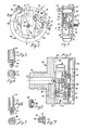
- Fig. 5 shows a pressure measuring device in which the measuring system according to the Figures 1 to 4 is applied.
- the pressure gauge includes a Housing 68, to which a device connection 70 belongs, which acts as a threaded pin is formed and with an external thread and a blind hole 72 formed in the threaded pin is provided.
- the Device connection 70 is used to connect the pressure measuring device a system that guides the substance, the pressure of which is generated by the Pressure measuring device to be measured.
- On the from the device connection 70 opposite side of the housing 68 is in this one transparent lens 74 used.
- the measuring system In the housing 68 and the window 74 enclosed space is the measuring system arranged so that its upper board 4 of the viewing window 74 is facing.
- the dial 12 On the upper board 4 of the measuring system the dial 12 attached, for which two molded on the dial 12 Pin 76 in the mounting holes 10 in the top Board 4 are locked. On the pointer pin 26 is a Pointer 78 inserted, its position over the dial 12 through the lens 74 is visible, so that the the pressure value indicated on the dial 12 by the pointer 78 can be.
- FIG. 5 the housing 68, the dial 12 and the Viewing window 74 shown in section, whereas the measuring system, that has the design according to Figures 1 to 4, in a Fig. 1 corresponding side view is shown.
- the Bourdon tube 48 shown broken away.
- Fig. 5 they are the other End 52 of the tubular spring 48 having half of the tubular spring 48 and the spring end piece 54 because of the broken view the Bourdon tube 48 not shown.
- dash-colon lines is the approach 62, which is before the drawing level of Fig. 5 is located.
- 5 shows the measuring system 2 in one position, which are obtained by rotating the measuring system from that shown in FIG Position about 180 ° around the axis of the pointer shaft 24 results.
- the lower board 6 On the inner wall 80 of the housing 68 are on the mounting holes 10 corresponding projections in the lower board 6 places 82 molded. These are not shown in Fig. 5. However, one of these protrusions 82 is shown in FIG. 6. To do that Attach the measuring system to the housing 68, the lower board 6 attached to the inner wall 80 such that the projections 82nd pass through the mounting holes 10. After that, the tabs 82 expanded and flattened in such a way that it Fig. 6 take the form shown. In this way, the lower one Board 6 riveted to the housing 68 and thereby the entire measuring system attached to the housing.
- a bore 84 is formed, the one End through a channel 86 with the blind hole 72 in connection stands and opens at its other end in the inner wall 80.
- the Bore 84 is sized and positioned to be the connection pin 42 receives sealed when the measuring system is attached to the housing 68 in the manner described above.
- the pressure connection thus produced between the Measuring system and the housing is shown in Fig. 7. 5 is The bore 84 is shown, but not the one inserted into it Connection pin 42.
- the measuring pressure passes through the blind hole 72, the channel 86, the bore 84, the bore 44 in the connecting pin 42 and the spring support 40 into the tubular spring 48.
- the other end 52 thereof and the spring end piece 54 are dependent on the measurement pressure deflected, this deflection by means of the toothed segment 32 and the pinion 28 is transmitted to the pointer 78.
- the connecting pin 42 of the measuring system does not simultaneously connect the device of the pressure measuring device, but rather that the device connection 72 and the connecting pin 42 two different Elements are.
- Pressure measuring device can be modified in that the rear device connection 70 through a so-called radial device connection is replaced by a radial, for example down in Fig. 5, replaced by the housing 68 protruding threaded pin is.
- only channel 86 would have to be another than the course shown.
- the measuring system including its connecting pin 42 need not be modified in this case to be, but can with reference to Figures 1 to 4 Retain the training described.
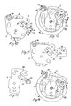
- FIG. 10 shows the lower board 6 of the measuring system in a FIG. 2 similar representation in the state in which it is with assembled the remaining elements of the pointer mechanism to the pointer mechanism 2 becomes.
- the two tabs 8 have already been bent over, and the spring support 40 is in the manner already explained above has been attached to the lower board 6.
- a web 88 is formed on the lower board 6, it merges into approach 62, which in turn merges and is formed in one piece with the spring end piece 54.
- Das Spring end piece 54 and extension 62 are thus in the position in FIG. 10 shown state firmly connected to the lower board 6.
- the spring end piece 54 and the shoulder 62 each have theirs final shape, which they as part of the finished measuring system according to Figures 1 to 4.
- that Spring end piece 54 and the shoulder 62 by means of the web 88 on the lower board 68 relative to the other elements of the lower Circuit board 6, in particular to the bearing hole 20 for the shaft 30 of the toothed segment 32, held in those relative positions, those for the finished measuring system as target positions for unpressurized Bourdon tube are specified.
- the elements forming the extension 62 and the spring end piece 54 are together with the other elements of the lower board 6th punched out of a flat metal sheet and then into the desired one Shape bent.
- the spring end piece 54 shown in Fig. 11 shows that it differs from the state shown in FIG. 10 alone distinguishes that the elements forming the spring end piece have not yet been bent.
- the bottom 56 and the two side walls 58 and 60 of Spring end piece still flat in the plane of the main section of the lower board 6. In this position, the bottom 56 and the two side walls 58 and 60 together with the other elements the lower board 6 has been punched.
- the spring end piece 54 is started from the state shown in Fig.
- the side wall 58 is bent about a bending line 90, the Bottom 56 is bent around a bending line 92 and becomes the side wall 60 bent around a bending line 94, so that the in the figures 10 and 2 shown shape of the spring end piece 54 results.
- the lower board 6 is in its state shown in FIG. 10 with the pointer shaft 24 carrying the pinion 28, which the toothed segment 32 supporting shaft 30, the bias spring 38 and the upper board 4 assembled or assembled to the pointer movement 2.
- the spring end piece 54 and the approach 62 due to its attachment to the lower board 6 components of the pointer mechanism.
- the tubular spring 48 with one end 50 in the Spring carrier 40 inserted and with its other end 52 in the Spring end piece 54 used.
- FIG. 12 shown arrangement of the tubular spring 48 and the pointer mechanism 2, at which at this time the spring end piece 54 and the Approach 62 are attached by means of the web 88. While the Bourdon tube 48 relative to the pointer 2 her shown in Fig.
- Removing the web 88 changes the positions the spring end piece 54 and the shoulder 62 relative to the elements of the pointer mechanism 2, since the removal of the web 88 has no influence on the shape of the tubular spring 48, which thus has the same shape before and after removal of the web 88.
- the spring end piece 54 on the finished measuring system assumes its target position with the same high accuracy, which in the manufacture of the lower board 6 with the molded on it Spring end piece 54 (see Fig. 10) is reached.
- Figures 8 and 9 show similar in Figures 3 and 4 Representations of a further embodiment of the spring support 40.
- the spring support 40 is not a sleeve trained rather than one from the sheet metal of the lower one Board 6 curved cap 96 which is integral with the lower Board 6 is formed and one in plan view according to Fig. 9 has a U-shaped cross section.
- the spring support 40 in shape cap 96 may be similar to that for the spring end 54 has been explained with reference to FIGS. 10 and 11, by bending elements of the stamped part for the lower board getting produced.
- the Cap 96 from the front of the lower board 6 before while on the back of the lower board 6 of this the connecting pin 42 protrudes with the bore 44.
- the connecting pin 42 not molded on the spring support but a separately manufactured one Part inserted into a hole in the bottom board 6 and attached to the lower board 6 by caulking is.
- the connecting pin 42 instead of on the back of the lower board 6 at the bottom 98 of the Cap 96 may be attached.
- the spring support 40 including its modifications are characterized by simple manufacture and small dimensions so that they make it easier to make the measuring system compact. Therefore, the described embodiments of the spring support including their modifications also with advantage be used in measuring systems in which the spring end piece before soldering with the tube spring not to one of the two Boards is attached.
- connection between the toothed segment and the spring end piece without one Drawbar can be a modification of the preferred Embodiment such a tie rod can be provided.
- the L-shaped projection 62 is omitted and is through the tie rod replaced.
- This modification remains unchanged, that the spring end piece is formed by a part that is first attached to one of the boards of the pointer mechanism and only after soldering the other end of the Bourdon tube the spring end piece has been separated.
- Fig. 13 shows the upper board 4, the spring end piece 54 and the shoulder 62 of the measuring system according to Figures 1 to 4, during the Approach 62 still with the upper board 4 by means of a web connected is.
- the approach 62 and the spring end piece 54 are in molded in the same way on the upper board 4, as this with reference to Figures 10 and 11 for the molding on the lower Board 6 has been explained.
- the pointer movement is made from the upper board 4 in its state shown in FIG.
- the spring support 40 on one of the two Boards namely the lower board 6, attached.
- this attachment the spring support is not provided on one of the two boards.
- 14 shows this further exemplary embodiment in a Fig. 12 similar representation during its manufacture.
- 8 and 9 of the measuring system is the spring support 40 with the lower one Circuit board 6 caulked or integrally formed on it, the connection of the spring support 40 to the lower board 46 is produced before the pointer mechanism is assembled.
- the Training provided according to the invention of the spring end piece as a part that before soldering the Bourdon tube to the spring end piece is attached to one of the two boards and after the Solder the Bourdon tube to the spring end piece from this board separated, can also be used for a measuring system that a conventional, with a molded Has device connection provided spring support with which the The pointer mechanism is screwed.
- the assembled Pointer movement, on one of which the spring end piece is attached is screwed to the spring support, after which the Bourdon tube with their ends inserted into the spring support and the spring end piece becomes. After soldering the two ends of the Bourdon tube to the The spring support and the spring end piece separate the spring end piece from the pointer movement.
- the measuring system for a pressure measuring device comprises a pointer mechanism with two boards in which a pointer shaft carrying a pinion and a toothed segment are rotatably mounted. Furthermore, the measuring system comprises an arcuate, metallic tubular spring which is soldered on the one hand to a spring support and on the other hand to a spring end piece. The spring end piece is connected to the toothed segment in such a way that the deflection of the spring end piece is transmitted to the toothed segment due to the measuring pressure.
- the spring end piece is formed by a part rigidly fastened to one of the two boards before the tube spring is soldered to the spring end piece and separated from this board after the tube spring is soldered to the spring end piece.
- the measuring system for a pressure measuring device comprises a pointer mechanism (2) with two plates (4, 6) in which a pointer shaft (24) carrying a pinion (28) and a toothed segment (32) are rotatably mounted.
- the measuring system further comprises an arcuately curved, metallic tubular spring (48) which is soldered on the one hand to a spring support (40) and on the other hand to a spring end piece (54).
- the spring end piece (54) is connected to the toothed segment (32) in such a way that the deflection of the spring end piece (54) is transmitted to the toothed segment (32) due to the measuring pressure.
- the spring end piece (54) is rigidly fastened to one of the two boards (4, 6) by one before the tube spring (48) is soldered to the spring end piece (54) and after the tube spring (48) is soldered to the spring end piece (54) part of this board.
- the spring end piece (54) is manufactured as a part which is firmly connected to one of the two boards (4, 6).
- the Bourdon tube (48) is soldered to the spring end piece (54) while it is still rigidly attached to the circuit board. Only then is the spring end piece (54) separated from the board.
- the spring support (40) is preferably formed or attached to one of the two boards (4, 6). The spring end piece (54) assumes its desired position with respect to the pointer mechanism (2) with high accuracy.
Landscapes
- Physics & Mathematics (AREA)
- General Physics & Mathematics (AREA)
- Measuring Fluid Pressure (AREA)
- A Measuring Device Byusing Mechanical Method (AREA)
Abstract
Description
- Fig. 1
- eine Seitenansicht eines Ausführungsbeispiels des erfindungsgemäßen Meßsystems, wobei eine Rohrfeder des Meßsystems teilweise weggebrochen dargestellt ist;
- Fig. 2
- eine Vordersicht des Meßsystem gemäß Fig. 1 bei Betrachtung in Richtung eines Pfeiles A in Fig. 1;
- Fig. 3
- eine Ansicht eines Federträgers des Meßsystems gemäß den Figuren 1 und 2 bei Betrachtung in Richtung eines Pfeiles B in Fig. 2;
- Fig. 4
- eine Draufsicht zu Fig. 3;
- Fig. 5
- eine Schnittdarstellung eines Druckmeßgerätes mit dem Meßsystem gemäß den Figuren 1 bis 4, wobei das Meßsystem in Seitenansicht dargestellt ist und dessen Rohrfeder teilweise weggebrochen dargestellt ist;
- Fig. 6
- eine ausschnittsweise Schnittdarstellung zur Erläuterung der Befestigung des Meßsystems des Druckmeßgerätes gemäß Fig. 5 an dessen Gehäuse;
- Fig. 7
- eine ausschnittsweise Schnittdarstellung zur Erläuterung eines Druckanschlusses des Druckmeßgerätes gemäß Fig. 5;
- Figuren 8 und 9
- den Figuren 3 und 4 entsprechende Darstellungen einer weiteren Ausführungsform des Federträgers;
- Fig. 10
- eine untere Platine des Meßsystems gemäß den Figuren 1 und 2 zu einem Zeitpunkt vor der Montage von dessen Zeigerwerk;
- Fig. 11
- die unter Platine gemäß Fig. 10 während ihrer Herstellung;
- Fig. 12
- das Meßsystem gemäß den Figuren 1 und 2 während eines Herstellungsschrittes desselben;
- Fig. 13
- eine obere Platine für eine abgewandelte Ausführungsform des Verfahrens zur Herstellung des Meßsystems gemäß den Figuren 1 und 2; und
- Fig. 14
- eine Figur 12 entsprechende Darstellung eines Meßsystems gemäß einem weiteren Ausführungsbeispiel.
Das Meßsystem für ein Druckmeßgerät umfaßt ein Zeigerwerk (2) mit zwei Platinen (4, 6), in denen eine ein Ritzel (28) tragende Zeigerwelle (24) sowie ein Zahnsegment (32) drehbar gelagert sind. Ferner umfaßt das Meßsystem eine bogenförmig gekrümmte, metallische Rohrfeder (48), die einerseits mit einem Federträger (40) und andererseits mit einem Federendstück (54) verlötet ist. Das Federendstück (54) ist mit dem Zahnsegment (32) derart verbunden, daß die Auslenkung des Federendstücks (54) aufgrund des Meßdrucks zum Zahnsegment (32) übertragen wird. Das Federendstück (54) ist durch ein vor dem Verlöten der Rohrfeder (48) mit dem Federendstück (54) an einer der beiden Platinen (4, 6) starr befestigtes und nach dem Verlöten der Rohrfeder (48) mit dem Federendstück (54) von dieser Platine abgetrenntes Teil gebildet. Im Zuge der Herstellung des Meßsystems wird das Federendstück (54) als ein mit einer der beiden Platinen (4, 6) fest verbundenes Teil gefertigt. Die Rohrfeder (48) wird mit dem Federendstück (54) verlötet, während dieses noch starr an der Platine befestigt ist. Erst danach wird das Federendstück (54) von der Platine getrennt. Vorzugsweise ist der Federträger (40) an einer der beiden Platinen (4, 6) angeformt oder befestigt. Das Federendstück (54) nimmt mit hoher Genauigkeit seine Sollstellung bezüglich des Zeigerwerks (2) ein.
Claims (19)
- Meßsystem für ein Druckmeßgerät, mit einem Zeigerwerk (2), das eine obere Platine (4) und eine untere Platine (6), die im wesentlichen parallel zueinander und mit Abstand voneinander angeordnet sind und miteinander verbunden sind, sowie eine ein Ritzel (28) tragende Zeigerwelle (24) und ein Zahnsegment (32) mit einem Hebelabschnitt (36) sowie einem verzahnten Abschnitt (34) aufweist, der mit dem Ritzel (28) kämmt, wobei die Zeigerwelle (24) und das Zahnsegment (32) drehbar in und zwischen den zwei Platinen (4, 6) gelagert sind und wobei die Zeigerwelle (24) einen von der oberen Platine (4) vorstehenden Zeigerzapfen (26) aufweist, und mit einer bogenförmig gekrümmten, metallischen Rohrfeder (48), die an ihrem einen Ende (50) mit einem metallischen Federträger (40) verbunden ist, durch den hindurch der Meßdruck in das Innere der Rohrfeder (48) gelangen kann, und die an ihrem anderen Ende (52) ein mit der Rohrfeder (48) starr verbundenes, metallisches Federendstück (54) trägt, das in Abhängigkeit von dem an die Rohrfeder (48) angelegten Meßdruck ausgelenkt wird, wobei das Federendstück (54) mit dem Hebelabschnitt (36) des Zahnsegmentes (32) derart verbunden ist, daß die Auslenkung des Federendstücks (54) zum Hebelabschnitt (36) übertragen wird, dadurch gekennzeichnet, daß das Federendstück (54) durch ein vor dem Verbinden der Rohrfeder (48) mit dem Federendstück (54) an einer der beiden Platinen (4, 6) befestigtes und nach dem Verbinden der Rohrfeder (48) mit dem Federendstück (54) von dieser Platine abgetrenntes Teil gebildet ist.
- Meßsystem nach Anspruch 1, dadurch gekennzeichnet, daß diejenige Platine (4, 6), an der das das Federendstück (54) bildende Teil vor dem Abtrennen befestigt ist, aus einem Metallblech besteht und daß das das Federendstück bildende Teil eine aus dem Metallblech gebogene Kappe ist, die vor dem Abtrennen einstückig mit dieser Platine ausgebildet und mit ihr mittels eines Steges (88, 100) verbunden ist.
- Meßsystem nach Anspruch 1 oder 2, dadurch gekennzeichnet, daß das das Federendstück (54) bildende Teil vor dem Abtrennen an der oberen Platine (4) befestigt ist.
- Meßsystem nach Anspruch 1 oder 2, dadurch gekennzeichnet, daß das das Federendstück (54) bildende Teil vor den Abtrennen an der unteren Platine (6) befestigt ist.
- Meßsystem nach einem der Ansprüche 1 bis 4, dadurch gekennzeichnet, daß der Federträger (40) an einer der beiden Platinen (4, 6) befestigt ist.
- Meßsystem nach Anspruch 5, dadurch gekennzeichnet, daß diejenige Platine (6), an der der Federträger (40) befestigt ist, aus einem Metallblech besteht und daß der Federträger (40) einstückig mit dieser Platine ausgebildet ist und in Form einer Kappe (96) mit U-förmigem Querschnitt aus dem Metallblech gebogen ist.
- Meßsystem nach Anspruch 6, gekennzeichnet durch einen mit einer Bohrung (54) versehenen Anschlußzapfen (42), dessen Bohrung in den Innenraum der Kappe (96) mündet.
- Meßsystem nach Anspruch 7, dadurch gekennzeichnet, daß der Anschlußzapfen (42) an derjenigen Platine (6) befestigt ist, mit der die den Federträger (40) bildenden Kappe (96) einstükkig ausgebildet ist, und daß der Anschlußzapfen (42) von dieser Platine (6) in zu der Kappe (96) entgegengesetzter Richtung vorsteht.
- Meßsystem nach Anspruch 5, dadurch gekennzeichnet, daß der Federträger (40) als Hülse (41) ausgebildet ist, die einen in ihrer Längsrichtung verlaufenden Schlitz (46) zur Aufnahme des einen Endes (50) der Rohrfeder (48) aufweist, und daß an der Hülse (41) ein mit einer Bohrung (44) versehener Anschlußzapfen (42) angeformt ist, dessen Bohrung (44) in den Innenraum der Hülse (41) mündet.
- Meßsystem nach Anspruch 9, dadurch gekennzeichnet, daß der Anschlußzapfen (42) in Längsrichtung der Hülse (41) und durch die die Hülse tragende Platine (6) verläuft, wobei der Anschlußzapfen (42) von dieser Platine in zu der Hülse entgegengesetzter Richtung vorsteht.
- Meßsystem nach einem der Ansprüche 5 bis 10, dadurch gekennzeichnet, daß der Federträger (40) an der unteren Platine (6) befestigt ist.
- Meßsystem nach einem der Ansprüche 1 bis 11, wobei das Zeigerwerk eine Vorspannfeder (38) aufweist, die auf das Zahnsegment (32) eine Vorspannkraft ausübt, dadurch gekennzeichnet, daß mit dem Federendstück (54) starr ein Anschlag (66) verbunden ist, an dem der Hebelabschnitt (36) des Zahnsegmentes (32) aufgrund der Vorspannkraft der Vorspannfeder (38) anliegt.
- Meßsystem nach Anspruch 12, dadurch gekennzeichnet, daß der Anschlag durch einen senkrecht zu den Ebenen der beiden Platinen (4, 6) verlaufenden Schenkel (66) eines L-förmigen Ansatzes (62) am Federendstück (54) gebildet ist und daß der Hebelabschnitt (36) auf der dem Federendstück (54) zugewandten Seite des Schenkels (66) anliegt.
- Meßsystem nach Anspruch 13, dadurch gekennzeichnet, daß der Hebelabschnitt (32) in einer zu den Ebenen der Platinen (4, 6) parallelen Ebene U-förmig ist.
- Meßsystem nach einem der Ansprüche 1 bis 14, dadurch gekennzeichnet, daß das Federendstück (54) mit dem anderen Ende (52) der Rohrfeder (48) verlötet ist.
- Verfahren zur Herstellung eines Meßsystems für ein Druckmeßgerät, wobei das Meßsystem ein Zeigerwerk (2) und eine bogenförmig gekrümmte, metallische Rohrfeder (48) aufweist, wobei das Zeigerwerk (2) eine obere Platine (4) und eine untere Platine (6), die im wesentlichen parallel zueinander und mit Abstand voneinander angeordnet sind und miteinander verbunden sind, sowie eine ein Ritzel (28) tragende Zeigerwelle (24) (24) und ein Zahnsegment (32) mit einem Hebelabschnitt (36) sowie einem verzahnten Abschnitt (34) aufweist, der mit dem Ritzel (28) kämmt, wobei die Zeigerwelle (24) (24) und das Zahnsegment (32) drehbar in und zwischen den zwei Platinen (4, 6) gelagert sind und wobei die Zeigerwelle (24) einen von der oberen Platine (4) vorstehenden Zeigerzapfen (26) aufweist, wobei die Rohrfeder (48) an ihrem einen Ende (50) mit einem metallischen Federträger (40) verbunden ist, durch den hindurch der Meßdruck in das Innere der Rohrfeder (48) gelangen kann, und an ihrem anderen Ende (52) ein metallisches Federendstück (54) trägt, das in Abhängigkeit von dem an die Rohrfeder (48) angelegten Meßdruck ausgelenkt wird, und wobei das Federendstück (54) mit dem Hebelabschnitt (36) des Zahnsegmentes (32) derart verbunden ist, daß die Auslenkung des Federendstücks (54) zum Hebelabschnitt (36) übertragen wird,
wobei das Verfahren die Schritte umfaßt,dadurch gekennzeichnet,daß das Zeigerwerk (2) montiert wird,daß das eine Ende (50) der Rohrfeder (48) mit dem Federträger (40) verbunden wird,daß das andere Ende (52) der Rohrfeder (48) mit dem Federendstück (54) starr verbunden wird, unddaß das Federendstück (54) in Verbindung mit dem Hebelabschnitt (36) des Zahnsegmentes (32) gebracht wird,daß das Federendstück (54) als mit einer der beiden Platinen (4, 6) fest verbundenes Teil gefertigt wird, so daß das Federendstück (54) Bestandteil des montierten Zeigerwerks (2) ist,daß das Federendstück (54) in Verbindung mit dem Hebelabschnitt (36) gebracht wird, bevor das andere Ende (52) der Rohrfeder (48) mit dem Federendstück (54) starr verbunden wird,daß das andere Ende (52) der Rohrfeder (48) mit dem Federendstück (54) starr verbunden wird, während dieses an der Platine (4, 6) befestigt ist, unddaß nach dem Verbinden der Rohrfeder (48) mit dem Federendstück (54) das Federendstück (54) von der Platine (4, 6) getrennt wird. - Verfahren nach Anspruch 16, dadurch gekennzeichnet, daß der Federträger (40) an einer der Platinen (4, 6) des Zeigerwerks (2) angeformt oder befestigt wird, bevor er mit dem einen Ende (50) der Rohrfeder (48) verbunden wird, so daß der Federträger (40) Bestandteil des montierten Zeigerwerks (2) ist, und daß das eine Ende (50) der Rohrfeder (48) in den Federträger (40) eingesetzt ist, während das andere Ende (52) der Rohrfeder (48) mit dem Federendstück (54) starr verbunden wird.
- Verfahren nach Anspruch 17, dadurch gekennzeichnet, daß das Verbinden des einen Endes (50) der Rohrfeder (48) mit dem Federträger (40) und das Verbinden des anderen Endes (52) der Rohrfeder (48) mit dem Federendstück (54) gleichzeitig erfolgen.
- Verfahren nach einem der Ansprüche 16 bis 18, dadurch gekennzeichnet, daß das andere Ende (52) der Rohrfeder (48) mit dem Federendstück (54) verlötet wird.
Priority Applications (14)
| Application Number | Priority Date | Filing Date | Title |
|---|---|---|---|
| DE59812185T DE59812185D1 (de) | 1998-07-24 | 1998-07-24 | Messsystem für ein Druckmessgerät |
| EP20010126670 EP1189049B1 (de) | 1998-07-24 | 1998-07-24 | Messsystem für ein Druckmessgerät |
| DE59812186T DE59812186D1 (de) | 1998-07-24 | 1998-07-24 | Verfahren zur Herstellung eines Messsystems für ein Druckmessgerät |
| EP01126676A EP1195589B1 (de) | 1998-07-24 | 1998-07-24 | Verfahren zur Herstellung eines Messsystems für ein Druckmessgerät |
| ES01126670T ES2225385T3 (es) | 1998-07-24 | 1998-07-24 | Sistema de medicion para un aparato manometrico. |
| EP98113938A EP0979991B1 (de) | 1998-07-24 | 1998-07-24 | Messsystem für ein Druckmessgerät sowie Verfahren zur Herstellung eines Messsystems für ein Druckmessgerät |
| DE59804523T DE59804523D1 (de) | 1998-07-24 | 1998-07-24 | Messsystem für ein Druckmessgerät sowie Verfahren zur Herstellung eines Messsystems für ein Druckmessgerät |
| ES98113938T ES2175567T3 (es) | 1998-07-24 | 1998-07-24 | Sistema de medicion para un aparato mnometrico, asi como procedimiento para fabricar un sistema de medicion para un aparato manometrico. |
| ES01126676T ES2225386T3 (es) | 1998-07-24 | 1998-07-24 | Procedimiento para fabricar un sistema de medicion para un aparato manometrico. |
| JP19896099A JP3215387B2 (ja) | 1998-07-24 | 1999-07-13 | 圧力ゲ−ジ用測定器および圧力ゲ−ジ用測定器の製造方法 |
| US09/353,264 US6301764B1 (en) | 1998-07-24 | 1999-07-14 | Measuring system for a pressure gauge and method for manufacturing a measuring system for a pressure gauge |
| CN99110637.7A CN1124477C (zh) | 1998-07-24 | 1999-07-22 | 压力表测量装置及其制造方法 |
| HK00105736.8A HK1026477B (en) | 1998-07-24 | 2000-09-12 | Measuring instrument for a pressure gauge and method for manufacturing a measuring instrument for a pressure gauge |
| US09/887,786 US6684712B2 (en) | 1998-07-24 | 2001-06-21 | Measuring instrument for a pressure gauge |
Applications Claiming Priority (1)
| Application Number | Priority Date | Filing Date | Title |
|---|---|---|---|
| EP98113938A EP0979991B1 (de) | 1998-07-24 | 1998-07-24 | Messsystem für ein Druckmessgerät sowie Verfahren zur Herstellung eines Messsystems für ein Druckmessgerät |
Related Child Applications (2)
| Application Number | Title | Priority Date | Filing Date |
|---|---|---|---|
| EP20010126670 Division EP1189049B1 (de) | 1998-07-24 | 1998-07-24 | Messsystem für ein Druckmessgerät |
| EP01126676A Division EP1195589B1 (de) | 1998-07-24 | 1998-07-24 | Verfahren zur Herstellung eines Messsystems für ein Druckmessgerät |
Publications (2)
| Publication Number | Publication Date |
|---|---|
| EP0979991A1 true EP0979991A1 (de) | 2000-02-16 |
| EP0979991B1 EP0979991B1 (de) | 2002-06-19 |
Family
ID=8232344
Family Applications (3)
| Application Number | Title | Priority Date | Filing Date |
|---|---|---|---|
| EP01126676A Expired - Lifetime EP1195589B1 (de) | 1998-07-24 | 1998-07-24 | Verfahren zur Herstellung eines Messsystems für ein Druckmessgerät |
| EP98113938A Expired - Lifetime EP0979991B1 (de) | 1998-07-24 | 1998-07-24 | Messsystem für ein Druckmessgerät sowie Verfahren zur Herstellung eines Messsystems für ein Druckmessgerät |
| EP20010126670 Expired - Lifetime EP1189049B1 (de) | 1998-07-24 | 1998-07-24 | Messsystem für ein Druckmessgerät |
Family Applications Before (1)
| Application Number | Title | Priority Date | Filing Date |
|---|---|---|---|
| EP01126676A Expired - Lifetime EP1195589B1 (de) | 1998-07-24 | 1998-07-24 | Verfahren zur Herstellung eines Messsystems für ein Druckmessgerät |
Family Applications After (1)
| Application Number | Title | Priority Date | Filing Date |
|---|---|---|---|
| EP20010126670 Expired - Lifetime EP1189049B1 (de) | 1998-07-24 | 1998-07-24 | Messsystem für ein Druckmessgerät |
Country Status (6)
| Country | Link |
|---|---|
| US (2) | US6301764B1 (de) |
| EP (3) | EP1195589B1 (de) |
| JP (1) | JP3215387B2 (de) |
| CN (1) | CN1124477C (de) |
| DE (3) | DE59804523D1 (de) |
| ES (3) | ES2175567T3 (de) |
Cited By (2)
| Publication number | Priority date | Publication date | Assignee | Title |
|---|---|---|---|---|
| US6592233B1 (en) | 2000-10-03 | 2003-07-15 | Nokia Mobile Phones Ltd. | Lighting device for non-emissive displays |
| CN110657903A (zh) * | 2019-10-31 | 2020-01-07 | 安徽南自电气股份有限公司 | 一种具有报警功能的压力表及其制造工艺 |
Families Citing this family (10)
| Publication number | Priority date | Publication date | Assignee | Title |
|---|---|---|---|---|
| DE10313986B4 (de) * | 2003-03-27 | 2005-02-10 | Armaturenbau Gmbh | Federelastisches Messelement |
| JP2009519357A (ja) * | 2005-12-13 | 2009-05-14 | 蘭欽 楊 | 水浸出法による植物油脂、植物粗蛋白及び植物繊維の調製方法 |
| JP2007218758A (ja) * | 2006-02-17 | 2007-08-30 | Fuji Bourdon Seisakusho:Kk | ブルドン管圧力計 |
| TWM300807U (en) * | 2006-06-07 | 2006-11-11 | Li-Jen Chen | Adjustable structure of sensory device for pressure meter |
| US7546773B2 (en) * | 2007-05-03 | 2009-06-16 | Scott Wu | Pressure gauge |
| JP5192402B2 (ja) * | 2009-01-16 | 2013-05-08 | 有限会社フジブルドン製作所 | ブルドン管圧力計 |
| CN105043654A (zh) * | 2015-05-11 | 2015-11-11 | 上海为民仪表厂 | 一种柴油机用压力表 |
| CN105784207A (zh) * | 2016-04-07 | 2016-07-20 | 博艳萍 | 一种弹簧测力计安装架 |
| CN209326840U (zh) | 2018-12-27 | 2019-08-30 | 热敏碟公司 | 压力传感器及压力变送器 |
| US12013299B1 (en) | 2023-02-10 | 2024-06-18 | Atrion Medical Products, Inc. | Pressure guage attachment system and method of assembly |
Citations (2)
| Publication number | Priority date | Publication date | Assignee | Title |
|---|---|---|---|---|
| DE2354473A1 (de) * | 1972-11-28 | 1974-05-30 | Carlo Alinari | Druckmesser nach dem bourdonfederprinzip |
| DE9215178U1 (de) * | 1992-11-07 | 1993-01-07 | Afriso-Euro-Index GmbH, 7129 Güglingen | Meßgerät |
Family Cites Families (12)
| Publication number | Priority date | Publication date | Assignee | Title |
|---|---|---|---|---|
| US3871095A (en) * | 1971-08-26 | 1975-03-18 | Citizen Watch Co Ltd | Process for the manufacture of hair spring collet |
| US4051730A (en) * | 1976-05-20 | 1977-10-04 | H. O. Trerice Co. | Condition responsive indicating instrument |
| US4100812A (en) * | 1977-01-05 | 1978-07-18 | Span Instruments | Dry pressure gauge with dampened needle movement |
| US4173150A (en) * | 1977-05-18 | 1979-11-06 | Span Instruments, Inc. | Sensor with adjustable pressure responsive detection and control |
| US4825699A (en) * | 1988-05-03 | 1989-05-02 | Roc Triad International Co., Ltd. | Non-deflectable adjustable bourdon gauge |
| US5507090A (en) * | 1994-07-20 | 1996-04-16 | Thiokol Corporation | Method for making stress sensors |
| DE59403196D1 (de) * | 1994-07-27 | 1997-07-24 | Wika Alexander Wiegand Gmbh | Verbindungsvorrichtung für ein Manometer und Verfahren zu seiner Herstellung |
| US5533414A (en) * | 1995-05-22 | 1996-07-09 | Huang; Tien-Tsai | Coupling device for coupling an indicator needle to an actuating unit in a pressure gauge |
| US5640992A (en) * | 1995-08-09 | 1997-06-24 | Huang; Tien-Tsai | Pressure gauge capable of automatically stopping supply of pressure from a pressure source |
| FR2741715B1 (fr) * | 1995-11-23 | 1997-12-26 | Air Liquide | Manometre a tube de bourdon |
| US5895861A (en) * | 1997-11-19 | 1999-04-20 | Weiss Instruments, Inc. | Combination pressure/temperature gauge employing two bourdon tubes |
| ES2260815T3 (es) * | 1998-12-15 | 2006-11-01 | WIKA ALEXANDER WIEGAND GMBH & CO. | Sistema de medicion para un aparato de medicion de la presion asi como aparato de medicion de la presion. |
-
1998
- 1998-07-24 ES ES98113938T patent/ES2175567T3/es not_active Expired - Lifetime
- 1998-07-24 EP EP01126676A patent/EP1195589B1/de not_active Expired - Lifetime
- 1998-07-24 DE DE59804523T patent/DE59804523D1/de not_active Expired - Lifetime
- 1998-07-24 EP EP98113938A patent/EP0979991B1/de not_active Expired - Lifetime
- 1998-07-24 DE DE59812185T patent/DE59812185D1/de not_active Expired - Lifetime
- 1998-07-24 ES ES01126670T patent/ES2225385T3/es not_active Expired - Lifetime
- 1998-07-24 ES ES01126676T patent/ES2225386T3/es not_active Expired - Lifetime
- 1998-07-24 EP EP20010126670 patent/EP1189049B1/de not_active Expired - Lifetime
- 1998-07-24 DE DE59812186T patent/DE59812186D1/de not_active Expired - Lifetime
-
1999
- 1999-07-13 JP JP19896099A patent/JP3215387B2/ja not_active Expired - Lifetime
- 1999-07-14 US US09/353,264 patent/US6301764B1/en not_active Expired - Lifetime
- 1999-07-22 CN CN99110637.7A patent/CN1124477C/zh not_active Expired - Fee Related
-
2001
- 2001-06-21 US US09/887,786 patent/US6684712B2/en not_active Expired - Lifetime
Patent Citations (2)
| Publication number | Priority date | Publication date | Assignee | Title |
|---|---|---|---|---|
| DE2354473A1 (de) * | 1972-11-28 | 1974-05-30 | Carlo Alinari | Druckmesser nach dem bourdonfederprinzip |
| DE9215178U1 (de) * | 1992-11-07 | 1993-01-07 | Afriso-Euro-Index GmbH, 7129 Güglingen | Meßgerät |
Cited By (2)
| Publication number | Priority date | Publication date | Assignee | Title |
|---|---|---|---|---|
| US6592233B1 (en) | 2000-10-03 | 2003-07-15 | Nokia Mobile Phones Ltd. | Lighting device for non-emissive displays |
| CN110657903A (zh) * | 2019-10-31 | 2020-01-07 | 安徽南自电气股份有限公司 | 一种具有报警功能的压力表及其制造工艺 |
Also Published As
| Publication number | Publication date |
|---|---|
| DE59812186D1 (de) | 2004-12-02 |
| DE59804523D1 (de) | 2002-07-25 |
| CN1124477C (zh) | 2003-10-15 |
| CN1254834A (zh) | 2000-05-31 |
| US20010029787A1 (en) | 2001-10-18 |
| EP0979991B1 (de) | 2002-06-19 |
| ES2225385T3 (es) | 2005-03-16 |
| US6301764B1 (en) | 2001-10-16 |
| EP1189049A1 (de) | 2002-03-20 |
| HK1026477A1 (en) | 2000-12-15 |
| ES2225386T3 (es) | 2005-03-16 |
| EP1189049B1 (de) | 2004-10-27 |
| EP1195589A1 (de) | 2002-04-10 |
| ES2175567T3 (es) | 2002-11-16 |
| JP2000046664A (ja) | 2000-02-18 |
| JP3215387B2 (ja) | 2001-10-02 |
| US6684712B2 (en) | 2004-02-03 |
| EP1195589B1 (de) | 2004-10-27 |
| DE59812185D1 (de) | 2004-12-02 |
Similar Documents
| Publication | Publication Date | Title |
|---|---|---|
| DE3738924C2 (de) | ||
| EP1189049B1 (de) | Messsystem für ein Druckmessgerät | |
| DE2659185A1 (de) | Verbindungsanordnung | |
| EP1014065B1 (de) | Messsystem für ein Druckmessgerät sowie Druckmessgerät | |
| DE2621037C2 (de) | ||
| DE4005678C2 (de) | Auslösedrehmomenteinstellvorrichtung für eine Überlastkupplung | |
| DE2807618A1 (de) | Stimmvorrichtung fuer ein saiteninstrument | |
| DE3428794A1 (de) | Verfahren zur herstellung eines doppelten bundes und ein nach diesem verfahren erhaltenes werkstueck mit doppeltem bund | |
| DE69208709T2 (de) | Brennstabbündel für Kernreaktor | |
| EP0011681B1 (de) | Barometer | |
| DE29717476U1 (de) | Hohlprofil-Befestigung | |
| EP0972688A2 (de) | Hubeinrichtung mit Schaftrohr und Stützrohr | |
| DE102004042552A1 (de) | "Vorrichtung zum Ausgleich der Drücke zwischen dem Inneren und Äußeren eines Zahnstangenlenksystems für Kraftfahrzeuge" | |
| DE3516684C2 (de) | ||
| DE3423052C2 (de) | ||
| DE10114476B4 (de) | Scheibenwischer sowie Verfahren zu dessen Herstellung | |
| DE19832215C1 (de) | Manometer | |
| EP3531193A1 (de) | Federscharnierteil für ein brillengestell, federscharnier mit einem solchen federscharnierteil, und verfahren zum montieren eines solchen federscharnierteils | |
| DE202006020729U1 (de) | Einstellvorrichtung für die Montage von Zahnstangen | |
| DE19840085A1 (de) | Befestigungsvorrichtung für Schläuche | |
| DE2809546A1 (de) | Zwischenstueck fuer schloesser, insbesondere fuer zylinderschloesser, sowie verfahren zu seiner herstellung | |
| DE29812768U1 (de) | Manometer | |
| DE3142509A1 (de) | Barometer | |
| EP1926565B1 (de) | Verfahren und vorrichtung zur herstellung von hohlprofilen | |
| EP3106265A1 (de) | Handwerkzeug und verfahren zu dessen herstellung |
Legal Events
| Date | Code | Title | Description |
|---|---|---|---|
| PUAI | Public reference made under article 153(3) epc to a published international application that has entered the european phase |
Free format text: ORIGINAL CODE: 0009012 |
|
| 17P | Request for examination filed |
Effective date: 19981222 |
|
| AK | Designated contracting states |
Kind code of ref document: A1 Designated state(s): DE ES FR GB IT |
|
| AX | Request for extension of the european patent |
Free format text: AL;LT;LV;MK;RO;SI |
|
| AKX | Designation fees paid |
Free format text: DE ES FR GB IT |
|
| GRAG | Despatch of communication of intention to grant |
Free format text: ORIGINAL CODE: EPIDOS AGRA |
|
| GRAG | Despatch of communication of intention to grant |
Free format text: ORIGINAL CODE: EPIDOS AGRA |
|
| GRAH | Despatch of communication of intention to grant a patent |
Free format text: ORIGINAL CODE: EPIDOS IGRA |
|
| GRAH | Despatch of communication of intention to grant a patent |
Free format text: ORIGINAL CODE: EPIDOS IGRA |
|
| GRAA | (expected) grant |
Free format text: ORIGINAL CODE: 0009210 |
|
| AK | Designated contracting states |
Kind code of ref document: B1 Designated state(s): DE ES FR GB IT |
|
| REG | Reference to a national code |
Ref country code: GB Ref legal event code: FG4D Free format text: NOT ENGLISH |
|
| REF | Corresponds to: |
Ref document number: 59804523 Country of ref document: DE Date of ref document: 20020725 |
|
| GBT | Gb: translation of ep patent filed (gb section 77(6)(a)/1977) |
Effective date: 20020723 |
|
| REG | Reference to a national code |
Ref country code: ES Ref legal event code: FG2A Ref document number: 2175567 Country of ref document: ES Kind code of ref document: T3 |
|
| PLBE | No opposition filed within time limit |
Free format text: ORIGINAL CODE: 0009261 |
|
| STAA | Information on the status of an ep patent application or granted ep patent |
Free format text: STATUS: NO OPPOSITION FILED WITHIN TIME LIMIT |
|
| 26N | No opposition filed |
Effective date: 20030320 |
|
| REG | Reference to a national code |
Ref country code: FR Ref legal event code: PLFP Year of fee payment: 19 |
|
| PGFP | Annual fee paid to national office [announced via postgrant information from national office to epo] |
Ref country code: IT Payment date: 20160721 Year of fee payment: 19 Ref country code: GB Payment date: 20160722 Year of fee payment: 19 |
|
| PGFP | Annual fee paid to national office [announced via postgrant information from national office to epo] |
Ref country code: FR Payment date: 20160722 Year of fee payment: 19 |
|
| PGFP | Annual fee paid to national office [announced via postgrant information from national office to epo] |
Ref country code: ES Payment date: 20160722 Year of fee payment: 19 |
|
| PGFP | Annual fee paid to national office [announced via postgrant information from national office to epo] |
Ref country code: DE Payment date: 20170724 Year of fee payment: 20 |
|
| GBPC | Gb: european patent ceased through non-payment of renewal fee |
Effective date: 20170724 |
|
| REG | Reference to a national code |
Ref country code: FR Ref legal event code: ST Effective date: 20180330 |
|
| PG25 | Lapsed in a contracting state [announced via postgrant information from national office to epo] |
Ref country code: GB Free format text: LAPSE BECAUSE OF NON-PAYMENT OF DUE FEES Effective date: 20170724 |
|
| PG25 | Lapsed in a contracting state [announced via postgrant information from national office to epo] |
Ref country code: FR Free format text: LAPSE BECAUSE OF NON-PAYMENT OF DUE FEES Effective date: 20170731 |
|
| REG | Reference to a national code |
Ref country code: DE Ref legal event code: R071 Ref document number: 59804523 Country of ref document: DE |
|
| PG25 | Lapsed in a contracting state [announced via postgrant information from national office to epo] |
Ref country code: IT Free format text: LAPSE BECAUSE OF NON-PAYMENT OF DUE FEES Effective date: 20170724 |
|
| REG | Reference to a national code |
Ref country code: ES Ref legal event code: FD2A Effective date: 20181029 |
|
| PG25 | Lapsed in a contracting state [announced via postgrant information from national office to epo] |
Ref country code: ES Free format text: LAPSE BECAUSE OF NON-PAYMENT OF DUE FEES Effective date: 20170725 |