EP0980295B1 - Procede et dispositif de production de brames d'acier - Google Patents
Procede et dispositif de production de brames d'acier Download PDFInfo
- Publication number
- EP0980295B1 EP0980295B1 EP98932038A EP98932038A EP0980295B1 EP 0980295 B1 EP0980295 B1 EP 0980295B1 EP 98932038 A EP98932038 A EP 98932038A EP 98932038 A EP98932038 A EP 98932038A EP 0980295 B1 EP0980295 B1 EP 0980295B1
- Authority
- EP
- European Patent Office
- Prior art keywords
- throat gap
- adjusters
- strand
- gap
- fact
- Prior art date
- Legal status (The legal status is an assumption and is not a legal conclusion. Google has not performed a legal analysis and makes no representation as to the accuracy of the status listed.)
- Expired - Lifetime
Links
- 238000000034 method Methods 0.000 title claims abstract description 13
- 229910000831 Steel Inorganic materials 0.000 title claims abstract description 6
- 239000010959 steel Substances 0.000 title claims abstract description 6
- 230000010355 oscillation Effects 0.000 claims abstract description 7
- 239000007788 liquid Substances 0.000 claims abstract description 6
- 238000009749 continuous casting Methods 0.000 claims description 7
- 238000004519 manufacturing process Methods 0.000 claims description 4
- 230000000694 effects Effects 0.000 claims 1
- 230000002889 sympathetic effect Effects 0.000 claims 1
- 238000005266 casting Methods 0.000 description 3
- 238000010586 diagram Methods 0.000 description 3
- 238000006073 displacement reaction Methods 0.000 description 3
- 238000005457 optimization Methods 0.000 description 3
- 238000007711 solidification Methods 0.000 description 3
- 230000008023 solidification Effects 0.000 description 3
- 238000001514 detection method Methods 0.000 description 2
- 238000011156 evaluation Methods 0.000 description 2
- 238000005259 measurement Methods 0.000 description 2
- 125000006850 spacer group Chemical group 0.000 description 2
- 230000015572 biosynthetic process Effects 0.000 description 1
- 238000004590 computer program Methods 0.000 description 1
- 238000001816 cooling Methods 0.000 description 1
- 239000000498 cooling water Substances 0.000 description 1
- 230000007423 decrease Effects 0.000 description 1
- 238000009826 distribution Methods 0.000 description 1
- 238000009827 uniform distribution Methods 0.000 description 1
Images


Classifications
-
- B—PERFORMING OPERATIONS; TRANSPORTING
- B22—CASTING; POWDER METALLURGY
- B22D—CASTING OF METALS; CASTING OF OTHER SUBSTANCES BY THE SAME PROCESSES OR DEVICES
- B22D11/00—Continuous casting of metals, i.e. casting in indefinite lengths
- B22D11/12—Accessories for subsequent treating or working cast stock in situ
- B22D11/1206—Accessories for subsequent treating or working cast stock in situ for plastic shaping of strands
-
- B—PERFORMING OPERATIONS; TRANSPORTING
- B22—CASTING; POWDER METALLURGY
- B22D—CASTING OF METALS; CASTING OF OTHER SUBSTANCES BY THE SAME PROCESSES OR DEVICES
- B22D11/00—Continuous casting of metals, i.e. casting in indefinite lengths
- B22D11/12—Accessories for subsequent treating or working cast stock in situ
- B22D11/128—Accessories for subsequent treating or working cast stock in situ for removing
-
- B—PERFORMING OPERATIONS; TRANSPORTING
- B22—CASTING; POWDER METALLURGY
- B22D—CASTING OF METALS; CASTING OF OTHER SUBSTANCES BY THE SAME PROCESSES OR DEVICES
- B22D11/00—Continuous casting of metals, i.e. casting in indefinite lengths
- B22D11/16—Controlling or regulating processes or operations
- B22D11/20—Controlling or regulating processes or operations for removing cast stock
Definitions
- the invention relates to a method for producing slabs from steel, in which one strand is a mold with liquid melt enclosed by the strand shell leaves and in a downstream strand guide the mouth width of in scaffolding stored guide rollers through lower and upper frame connecting Adjusting elements is continuously adjusted, and an associated device for this.
- DE 26 12 094 C2 describes a device for changing the distance from one another opposite frame or pair connected by tie rods Scaffolding parts of a strand guide are known, in which bushes are provided which Are rotatable with the help of pressure cylinders.
- the movable frame parts are through Printing cylinder connected, being between the movable frame part and the interchangeable spacers for the purpose of setting a predeterminable Roller distance can be used.
- the main aim of the subject of this patent is only sufficient contact pressure for apply the transport of the strand or adjust the mouth width.
- the invention has set itself the goal of creating a method and a device with which the mouth width can be adjusted exactly over the entire strand guide with simple means and, moreover, the current position of the Let the bottom of the sump be determined within the slab. Furthermore, the device should be able to safely guide the cold strand with a simple structure.
- the invention achieves the aim by the features of method claim 1 and Device claim 6.
- an oscillation variable is selected that the dynamic influences on the relatively thin strand shell after leaving the mold negligibly small.
- the amplitude of the oscillating jaw width is one size set, which prevents plastic deformation of the strand shell.
- the current jaw width is recorded via displacement measuring elements and fed to a computer.
- the actuating force of the adjusting elements for continuously changing the jaw width is determined and also fed to the computer.
- the amplitude is monitored by means of a computer program and, as the amplitude of the actuating force increases, the jaw width is set to a predeterminable dimension and / or the jaw width of the guide rollers is guided in a pressure-controlled manner via at least one of the adjusting elements which continuously adjust the jaw width.
- the amplitude of the actuating force is a measure of the solidification of the strand. That is, a relatively small amplitude of the actuating force is encountered when the Strand shell is still thin and a large liquid sump is present. The Amplitude reaches its greatest value when the strand is solidified.
- the optimal jaw width in the Set the way that the oscillation detects whether the trend towards the larger one or to the smaller mouth width away from the optimal mouth width then occurs with counteract specific measures.
- the actuating force F is in the form of the internal width s a hysteresis curve.
- the deformation work of a segment during the stroke, i.e. the area within the hysteresis curve can be evaluated using evaluation software calculated and the strand consistency can be concluded.
- the Overall, the hysteresis curve has a relatively small area when the shell is still thin and the swamp is relatively large.
- the hysteresis curve shows a relatively large one Surface when the shell continues to grow and the sump volume decreases.
- the Hysteresis takes a particularly slim form when the strand is complete is completely frozen.
- the invention enables an optimization of the production performance in qualitative and achieved in quantitative terms, namely in terms of qualitative optimization through always optimally implemented soft reduction (locally, dynamic soft reduction) and in terms of quantitative optimization of production performance through the possibility of being able to make maximum use of the machine length at at the same time high operational reliability.
- thermal tracking software in your Accuracy can be improved significantly.
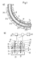
- FIG. 1 shows the diagram of a continuous casting plant with a mold 11, at the mouth of which a slab B emerges and is guided by stands 21.1 to 21.5.
- the slab the strand shell of which gradually solidifies, there is a sump S up to a sump tip S s .
- adjustment elements 31 are only shown in the framework 21.4.
- a scaffold 21 which has an upper frame 22 and a lower frame 23, the adjustment elements 31 the mouth width between the guide rollers 24 arranged on them determine.
- One of the guide rollers is a drive roller 25, whose function in the Figure 5 is described in more detail.
- the adjustment elements have a tie rod 32, which is regularly in the subframe 23 is attached and has at its opposite end a piston 33 which in a cylinder 34 is guided.
- the individual stands 21 have at least four Adjustment elements 31, the cylinders 34 of which are connected to an actuator 35.
- the adjustment element 31 with a displacement measuring element equipped, which is connected to a displacement sensor, which metrologically connected to a computer.
- the cylinder 34 has a pressure measuring element 43 equipped, which is connected to a pressure transducer 44, which is also on the computer is metrologically connected.
- the computer 45 works in terms of control together with the actuator 35.
- the actuator is connected to an oscillator.
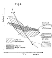
- the mouth width is plotted against time in the upper part of the picture.
- the desired slab thickness (center line c) Width of mouth changed. In the present case it is a sine wave. But there are other forms of vibration possible and provided.
- the positioning force F is plotted against time in the lower part of the picture. In the left part of the picture, the positioning force has a relatively small amplitude. Has in the right part the amplitude of the positioning force increases significantly.
- the swamp of type ⁇ has a thin shell with one swamp less Viscosity, the type ⁇ a much thicker shell and at the same time a sump with high viscosity and the type ⁇ is completely solidified.
- the image representations shown here show a uniform distribution of the hysteresis and thus the optimal mouth width once s ⁇ or also s ⁇ .
- FIG. 5 shows a scaffold in three different operating states.
- the Item numbers correspond to those already listed in the pictures above.
- the upper part of the picture is the normal casting operation, with one on all cylinders Position control is carried out.
- the scaffold entry is on Provided a drivable guide roller in the upper frame.
- the operation is shown when the strand has solidified.
- the im Area of the drivable guide roller arranged for the cylinder Adjustment elements are pressure-controlled and the cylinders shown downstream are position controlled.
Landscapes
- Engineering & Computer Science (AREA)
- Mechanical Engineering (AREA)
- Continuous Casting (AREA)
- Cell Electrode Carriers And Collectors (AREA)
- Metal Rolling (AREA)
- Basic Packing Technique (AREA)
- Conveying And Assembling Of Building Elements In Situ (AREA)
- Heat Treatment Of Steel (AREA)
- Coating With Molten Metal (AREA)
Claims (9)
- Procédé pour produire des brames en acier, dans lequel la barre quitte une coquille avec de la matière en fusion liquide entourée par la coque de barre et, dans un guide de barre disposé en aval, l'embouchure de rouleaux de guidage montés dans des cages est réglée de façon continue par des éléments de réglage reliant le bâti inférieur et le bâti supérieur,
caractérisé par les étapes suivantes :(a) l'embouchure (s) est modifiée avec une amplitude pouvant être définie (Acons.) de façon oscillante autour d'un axe central pouvant être prédéfini (c) de l'embouchure pendant l'extraction de la barre de la coquille de façon que les influences dynamiques sur les rouleaux de guidage sur la coque de barre soient négligeables et qu'il ne se produise aucune déformation plastique de la coque de barre,(b) l'embouchure actuelle (s) est déterminée,(c) simultanément, la force de réglage (F) des éléments de réglage, ainsi que l'amplitude (Aréel) de la force de réglage, sont déterminées, et(d) lorsque l'amplitude (Aréel) de la force de réglage (F) croít, l'embouchure (s) est réglée à une dimension pouvant être définie et/ou est guidée, de façon réglée en pression, par l'intermédiaire d'au moins un élément de réglage. - Procédé selon la revendication 1,
caractérisé en ce que la fréquence (f) d'oscillation de l'embouchure vaut 0,05 à 5,0 Hz. - Procédé selon la revendication 1,
caractérisé en ce que la force de réglage actuelle (F) est détectée par traitement de données électronique et est traitée de façon que la force de réglage (F), en fonction de l'embouchure réelle (s), se présente, en première approximation, comme deux courbes : - Procédé selon la revendication 3,
caractérisé en ce qu'un côté F1 = a-m1·s correspond à une embouchure plus petite et le second côté F2 = b-m2.s à une embouchure plus grande que l'embouchure optimale (s) existant à l'intersection (P) et en ce que, de façon dépendant de l'allure de la relation F = f (s), le degré et la direction du réglage de l'embouchure (s) sont adaptés. - Procédé selon la revendication 4 ou 3,
caractérisé en ce que l'allure de la force de réglage (F), en seconde approximation, possède la forme d'une hystérèse, en ce que l'étalement de la force de réglage (F), relativement à une embouchure correspondante (s), constitue une mesure de la viscosité du noyau liquide se trouvant dans la brame, et en ce que, de façon dépendant de la viscosité trouvée, il en est tiré des conclusions sur la position de la pointe du noyau liquide, et le réglage de l'embouchure est adapté. - Dispositif de coulée continue pour produire des brames en acier, comportant une coquille et un guide de barre disposé en aval, qui possède des cages ayant des bâtis inférieur et supérieur, sur lesquels sont prévus des rouleaux de guidage, dont l'embouchure peut être réglée de façon continue par des éléments de réglage reliant les bâtis, pour la mise en oeuvre du procédé selon la revendication 1,
caractérisé en ce que des capteurs de déplacement (42) et des capteurs de pression (44), qui détectent la force de réglage des éléments de réglage (31), sont prévus, grâce auxquels l'embouchure (s) des rouleaux de guidage (24) peut être déterminée, en ce que les capteurs de déplacement (42) sont reliés à un calculateur (45) qui est raccordé à un actionneur (35), grâce auquel les éléments de réglage (31) peuvent être mis en service en pouvant être commandés en pression et/ou en déplacement pour le réglage de l'embouchure, et en ce qu'un oscillateur (46) est prévu grâce auquel les éléments de réglage (31) peuvent être excités à une oscillation à l'extérieur de l'oscillation de résonance par rapport aux cages de barre (21). - Dispositif de coulée continue selon la revendication 6,
caractérisé en ce que les capteurs de déplacement (42) présentent des éléments de mesure (41) qui sont reliés directement à l'élément de réglage (31), sont raccordés en particulier, dans le cas d'éléments de réglage hydrauliques, au piston de réglage (33). - Dispositif de coulée continue selon la revendication 6,
caractérisé en ce qu'un des rouleaux de guidage externes (24) du bâti supérieur (22) peut être entraíné, en ce que les éléments de réglage (31) associés au rouleau de guidage pouvant être entraíné (25) peuvent être reliés au calculateur (45) par l'intermédiaire de dispositifs de réglage de pression (43, 44), et les autres éléments de réglage (31) par l'intermédiaire de dispositifs de réglage de position (41, 42). - Dispositif de coulée continue selon la revendication 8,
caractérisé en ce que les éléments de réglage (31) sont montés dans le bâti supérieur ou le bâti inférieur (22, 23) de façon que les bâtis (22, 23) puissent être positionnés de façon inclinée l'un par rapport à l'autre, l'ouverture plus grande de l'embouchure étant éloignée des rouleaux d'entraínement (25).
Applications Claiming Priority (3)
| Application Number | Priority Date | Filing Date | Title |
|---|---|---|---|
| DE19720768 | 1997-05-07 | ||
| DE19720768A DE19720768C1 (de) | 1997-05-07 | 1997-05-07 | Verfahren und Vorrichtung zum Erzeugen von Brammen aus Stahl |
| PCT/DE1998/001198 WO1998050185A1 (fr) | 1997-05-07 | 1998-04-27 | Procede et dispositif de production de brames d'acier |
Publications (2)
| Publication Number | Publication Date |
|---|---|
| EP0980295A1 EP0980295A1 (fr) | 2000-02-23 |
| EP0980295B1 true EP0980295B1 (fr) | 2001-10-17 |
Family
ID=7829787
Family Applications (1)
| Application Number | Title | Priority Date | Filing Date |
|---|---|---|---|
| EP98932038A Expired - Lifetime EP0980295B1 (fr) | 1997-05-07 | 1998-04-27 | Procede et dispositif de production de brames d'acier |
Country Status (10)
| Country | Link |
|---|---|
| US (1) | US6701999B2 (fr) |
| EP (1) | EP0980295B1 (fr) |
| KR (1) | KR100531125B1 (fr) |
| AT (1) | ATE206973T1 (fr) |
| AU (1) | AU8209098A (fr) |
| BR (1) | BR9809604A (fr) |
| DE (2) | DE19720768C1 (fr) |
| ID (1) | ID20520A (fr) |
| TW (1) | TW404869B (fr) |
| WO (1) | WO1998050185A1 (fr) |
Cited By (3)
| Publication number | Priority date | Publication date | Assignee | Title |
|---|---|---|---|---|
| DE102007006458A1 (de) | 2007-02-05 | 2008-08-07 | Sms Demag Ag | Stranggießeinrichtung zum Erzeugen von Brammen aus Stahl |
| DE102009031651A1 (de) | 2009-07-03 | 2011-01-05 | Sms Siemag Aktiengesellschaft | Verfahren zum Bestimmen der Lage der Sumpfspitze eines gegossenen Metallstrangs und Stranggießanlage |
| WO2011124466A1 (fr) * | 2010-04-09 | 2011-10-13 | Sms Siemag Ag | Procédé et dispositif pour ajuster la position de l'extrémité du cratère liquide dans une barre de coulée |
Families Citing this family (25)
| Publication number | Priority date | Publication date | Assignee | Title |
|---|---|---|---|---|
| DE19809807C2 (de) * | 1998-03-09 | 2003-03-27 | Sms Demag Ag | Anstellverfahren für ein Rollensegment einer Stranggießanlage |
| DE10039016B4 (de) * | 2000-08-10 | 2010-02-25 | Sms Siemag Aktiengesellschaft | Verfahren zum Erzeugen von Brammen aus Stahl |
| DE10042079A1 (de) | 2000-08-26 | 2002-04-25 | Sms Demag Ag | Stranggießanlage mit Soft-Reduction-Strecke |
| DE10057160A1 (de) * | 2000-11-16 | 2002-05-29 | Sms Demag Ag | Verfahren und Vorrichtung zum Herstellen von Dünnbrammen |
| AT409465B (de) * | 2000-12-12 | 2002-08-26 | Voest Alpine Ind Anlagen | Verfahren zum einstellen eines giessspaltes an einer strangführung einer stranggiessanlage |
| DE10122118A1 (de) * | 2001-05-07 | 2002-11-14 | Sms Demag Ag | Verfahren und Vorrichtung zum Stranggiessen von Blöcken, Brammen und Dünnbrammen |
| TWI253360B (en) * | 2001-12-18 | 2006-04-21 | Sms Demag Ag | Feed opening adjustment of segments for continuous casting systems |
| EP1478479B1 (fr) * | 2002-02-22 | 2005-12-14 | SMS Demag Aktiengesellschaft | Procede de coulee continue et de faconnage direct d'un metal, notamment d'une barre de coulee en materiaux a base d'acier |
| DE10224533A1 (de) * | 2002-05-31 | 2003-12-18 | Sms Demag Ag | Verfahren zur Ermittlung der Reibkraft bei einem erzwungenen Schwingungen ausgesetzten System |
| DE10349962B3 (de) * | 2003-10-24 | 2005-06-02 | Ingo Dr. Schubert | Anordnung zur Ermittlung der Konsistenz eines Gießstranges in einer Stranggießalage und/oder Maulweite derselben |
| DE102004002783A1 (de) * | 2004-01-20 | 2005-08-04 | Sms Demag Ag | Verfahren und Einrichtung zum Bestimmen der Lage der Sumpfspitze im Gießstrang beim Stranggießen von flüssigen Metallen, insbesondere von flüssigen Stahlwerkstoffen |
| DE102004054296B4 (de) * | 2004-11-09 | 2021-11-11 | Sms Group Gmbh | Steuer- und / oder Regeleinrichtung für ein Stützrollengerüst einer Stranggießvorrichtung für Metalle, insbesondere für Stahlwerkstoffe |
| DE102005037138A1 (de) * | 2005-08-06 | 2007-02-08 | Sms Demag Ag | Verfahren und Vorrichtung zum präzisen Positionieren einer Anzahl zusammenwirkender Walz- oder Rollenelemente |
| DE102006016375B4 (de) * | 2006-04-05 | 2023-02-16 | Sms Group Gmbh | Verfahren und Einrichtung zum Bestimmen der Kernerstarrung und/oder der Sumpfspitze beim Stranggießen von Metallen, insbesondere von Stahlwerkstoffen |
| DE102007016045A1 (de) * | 2007-03-30 | 2008-10-02 | Sms Demag Ag | Vorrichtung zum hydraulischen Anstellen von Bauteilen |
| RU2362650C2 (ru) * | 2007-06-26 | 2009-07-27 | Общество с ограниченной ответственностью "Уралмаш-Инжиниринг" | Способ регулирования скорости слитка в роликовом аппарате машины непрерывного литья заготовок |
| DE102008015008B4 (de) * | 2008-03-19 | 2024-02-01 | Sms Group Gmbh | Verfahren zum Betreiben einer Strangführungseinrichtung |
| JP5600929B2 (ja) * | 2008-12-10 | 2014-10-08 | Jfeスチール株式会社 | 連続鋳造鋳片の製造方法 |
| DE102012009870A1 (de) * | 2012-05-15 | 2013-11-21 | Sms Siemag Ag | Verfahren und Strangführung zur Beeinflussung der Erstarrung des teilweise noch flüssigen Kernes während des Stranggießens |
| CN103048242A (zh) * | 2013-01-21 | 2013-04-17 | 中冶赛迪电气技术有限公司 | 连铸坯固相率和凝固末端的检测方法及检测装置 |
| US10888920B2 (en) * | 2016-12-08 | 2021-01-12 | Aktiebolaget Skf | Monitoring and control system for continuous casting machine |
| CN110303129B (zh) * | 2019-06-26 | 2021-03-09 | 山东钢铁股份有限公司 | 一种宽厚板坯的制造方法 |
| EP3878574A1 (fr) * | 2020-03-13 | 2021-09-15 | Primetals Technologies Austria GmbH | Détermination de l'état des rouleaux de guidage de barre par évaluation des vibrations |
| IT202200006581A1 (it) * | 2022-04-04 | 2023-10-04 | Danieli Off Mecc | Segmento di un dispositivo di soft reduction per eseguire una soft reduction di bramme |
| CN114918393B (zh) * | 2022-06-09 | 2024-07-19 | 吉林建龙钢铁有限责任公司 | 一种控制中、低碳钢结晶器液位周期性波动的方法 |
Family Cites Families (13)
| Publication number | Priority date | Publication date | Assignee | Title |
|---|---|---|---|---|
| DE1213575B (de) * | 1962-06-29 | 1966-03-31 | Demag Ag | Richtmaschine fuer Stranggiessanlagen |
| US3891025A (en) * | 1972-06-29 | 1975-06-24 | Schloemann Siemag Ag | Apparatus for withdrawing a casting and feeding a dummy bar in a continuous casting machine for steel |
| US4030533A (en) * | 1974-06-24 | 1977-06-21 | Nippon Steel Corporation | Continuous casting system |
| AT335649B (de) * | 1975-03-25 | 1977-03-25 | Voest Ag | Strangfuhrung an einer stranggiessanlage |
| DE3106531A1 (de) * | 1981-02-21 | 1982-09-09 | SMS Schloemann-Siemag AG, 4000 Düsseldorf | Treib- und richtmaschine fuer stranggiessanlagen |
| US4953614A (en) * | 1987-04-09 | 1990-09-04 | Herbert Lemper | Modular continuous caster |
| US5152334A (en) * | 1990-05-02 | 1992-10-06 | Mesta International | Guide roll assembly and method of guiding cast strand |
| US5488987A (en) * | 1991-10-31 | 1996-02-06 | Danieli & C. Officine Meccaniche Spa | Method for the controlled pre-rolling of thin slabs leaving a continuous casting plant, and relative device |
| DE4341719C2 (de) * | 1993-12-03 | 2001-02-01 | Mannesmann Ag | Einrichtung zum Stranggießen von Stahl |
| US6044895A (en) * | 1993-12-21 | 2000-04-04 | Siemens Aktiengesellschaft | Continuous casting and rolling system including control system |
| JP3008821B2 (ja) * | 1994-07-29 | 2000-02-14 | 住友金属工業株式会社 | 薄鋳片の連続鋳造方法および装置 |
| US6102101A (en) * | 1995-10-18 | 2000-08-15 | Sumitomo Metal Industries, Ltd. | Continuous casting method and apparatus thereof |
| EP0776708B1 (fr) * | 1995-11-28 | 1999-01-20 | DANIELI & C. OFFICINE MECCANICHE S.p.A. | Procédé et dispositif pour le prélaminage controlé de brames minces sortant d'une installation de coulée continue |
-
1997
- 1997-05-07 DE DE19720768A patent/DE19720768C1/de not_active Expired - Lifetime
-
1998
- 1998-04-27 US US09/423,482 patent/US6701999B2/en not_active Expired - Lifetime
- 1998-04-27 AT AT98932038T patent/ATE206973T1/de active
- 1998-04-27 DE DE59801786T patent/DE59801786D1/de not_active Expired - Lifetime
- 1998-04-27 WO PCT/DE1998/001198 patent/WO1998050185A1/fr not_active Ceased
- 1998-04-27 KR KR10-1999-7010332A patent/KR100531125B1/ko not_active Expired - Lifetime
- 1998-04-27 AU AU82090/98A patent/AU8209098A/en not_active Abandoned
- 1998-04-27 EP EP98932038A patent/EP0980295B1/fr not_active Expired - Lifetime
- 1998-04-27 BR BR9809604-4A patent/BR9809604A/pt not_active Application Discontinuation
- 1998-05-06 ID IDP980663A patent/ID20520A/id unknown
- 1998-05-07 TW TW087107057A patent/TW404869B/zh not_active IP Right Cessation
Cited By (4)
| Publication number | Priority date | Publication date | Assignee | Title |
|---|---|---|---|---|
| DE102007006458A1 (de) | 2007-02-05 | 2008-08-07 | Sms Demag Ag | Stranggießeinrichtung zum Erzeugen von Brammen aus Stahl |
| DE102009031651A1 (de) | 2009-07-03 | 2011-01-05 | Sms Siemag Aktiengesellschaft | Verfahren zum Bestimmen der Lage der Sumpfspitze eines gegossenen Metallstrangs und Stranggießanlage |
| WO2011000549A1 (fr) | 2009-07-03 | 2011-01-06 | Sms Siemag Ag | Procédé pour déterminer la position de l'extrémité du cratère liquide d'une barre de métal coulée et installation de coulée continue |
| WO2011124466A1 (fr) * | 2010-04-09 | 2011-10-13 | Sms Siemag Ag | Procédé et dispositif pour ajuster la position de l'extrémité du cratère liquide dans une barre de coulée |
Also Published As
| Publication number | Publication date |
|---|---|
| ID20520A (id) | 1999-01-07 |
| US6701999B2 (en) | 2004-03-09 |
| US20030145976A1 (en) | 2003-08-07 |
| AU8209098A (en) | 1998-11-27 |
| DE19720768C1 (de) | 1999-01-14 |
| EP0980295A1 (fr) | 2000-02-23 |
| WO1998050185A1 (fr) | 1998-11-12 |
| DE59801786D1 (de) | 2001-11-22 |
| ATE206973T1 (de) | 2001-11-15 |
| BR9809604A (pt) | 2000-10-03 |
| KR100531125B1 (ko) | 2005-11-24 |
| KR20010012379A (ko) | 2001-02-15 |
| TW404869B (en) | 2000-09-11 |
Similar Documents
| Publication | Publication Date | Title |
|---|---|---|
| EP0980295B1 (fr) | Procede et dispositif de production de brames d'acier | |
| DE69425507T2 (de) | Verfahren und vorrichtung zum walzengiessen dunner bleche | |
| EP0545104A2 (fr) | Procédé et dispositif pour coulée continue des lingots ou blooms | |
| DE4436328C5 (de) | Verfahren und Anlage zum Stranggießen | |
| EP1478479B1 (fr) | Procede de coulee continue et de faconnage direct d'un metal, notamment d'une barre de coulee en materiaux a base d'acier | |
| DE2133144B2 (de) | Verfahren und Vorrichtung zum Ausfordern und Richten eines Stranges in einer Stranggiessanlage | |
| DE60034273T2 (de) | Verfahren und Vorrichtung zum Giessen eines Metallstranges | |
| AT408197B (de) | Verfahren zum stranggiessen eines metallstranges | |
| EP0834364B1 (fr) | Méthode et dispositif pour des machines de coulée continue à haute vitesse avec réduction d'épaisseur pendant la solidification | |
| EP0627968B1 (fr) | Procede de coulee continue de metal, notamment d'acier, pour la production de billettes et de blooms | |
| EP3515634B1 (fr) | Réglage de la conicité de petit côté d'une lingotière de coulée continue, procédé et dispositif | |
| DE102020209794A1 (de) | Verfahren zur Steuerung oder Regelung der Temperatur eines Gießstrangs in einer Stranggießanlage | |
| EP1132161B1 (fr) | Procédé pour la coulée continue de brames, en particulier de brames minces | |
| DE10160636B4 (de) | Verfahren zum Einstellen eines Gießspaltes an einer Strangführung einer Stranggießanlage und Stranggießanlage zur Durchführung des Verfahrens | |
| EP1307309B1 (fr) | Procede de fabrication de brames d'acier | |
| EP3173166A1 (fr) | Procédé et dispositif de réglage de la largeur d'une barre métallique coulée en continu | |
| WO2002040201A2 (fr) | Procede et dispositif de fabrication de brames minces | |
| DE69132248T2 (de) | Vorrichtung zum Ausziehen eines Gussstranges aus eine Horizontalstranggiessanlage | |
| EP1385656B1 (fr) | Procede pour la coulee continue de blocs, de brames ou de brames minces | |
| DE2853868C2 (de) | Verfahren zum Stranggießen von Stahl sowie dementsprechend hergestellter Stahlstrang | |
| DE69303309T3 (de) | Verfahren zum Stranggiessen | |
| DE2063545C3 (de) | Viereckige Stranggießkokille | |
| EP0946318B1 (fr) | Procede et installation de coulee continue de brames fines | |
| DE69000282T2 (de) | Verfahren und vorrichtung zur herstellung von duennen metallprodukten mittels strangguss. | |
| AT406745B (de) | Verfahren und vorrichtung zum ändern der dicke eines stranges |
Legal Events
| Date | Code | Title | Description |
|---|---|---|---|
| PUAI | Public reference made under article 153(3) epc to a published international application that has entered the european phase |
Free format text: ORIGINAL CODE: 0009012 |
|
| 17P | Request for examination filed |
Effective date: 19991008 |
|
| AK | Designated contracting states |
Kind code of ref document: A1 Designated state(s): AT DE FR GB IT LU NL |
|
| RAP1 | Party data changed (applicant data changed or rights of an application transferred) |
Owner name: SMS DEMAG AG |
|
| 17Q | First examination report despatched |
Effective date: 20000613 |
|
| GRAG | Despatch of communication of intention to grant |
Free format text: ORIGINAL CODE: EPIDOS AGRA |
|
| GRAG | Despatch of communication of intention to grant |
Free format text: ORIGINAL CODE: EPIDOS AGRA |
|
| GRAH | Despatch of communication of intention to grant a patent |
Free format text: ORIGINAL CODE: EPIDOS IGRA |
|
| GRAH | Despatch of communication of intention to grant a patent |
Free format text: ORIGINAL CODE: EPIDOS IGRA |
|
| GRAA | (expected) grant |
Free format text: ORIGINAL CODE: 0009210 |
|
| AK | Designated contracting states |
Kind code of ref document: B1 Designated state(s): AT DE FR GB IT LU NL |
|
| REF | Corresponds to: |
Ref document number: 206973 Country of ref document: AT Date of ref document: 20011115 Kind code of ref document: T |
|
| GBT | Gb: translation of ep patent filed (gb section 77(6)(a)/1977) |
Effective date: 20011017 |
|
| REF | Corresponds to: |
Ref document number: 59801786 Country of ref document: DE Date of ref document: 20011122 |
|
| REG | Reference to a national code |
Ref country code: GB Ref legal event code: IF02 |
|
| ET | Fr: translation filed | ||
| PGFP | Annual fee paid to national office [announced via postgrant information from national office to epo] |
Ref country code: NL Payment date: 20020328 Year of fee payment: 5 |
|
| PGFP | Annual fee paid to national office [announced via postgrant information from national office to epo] |
Ref country code: LU Payment date: 20020404 Year of fee payment: 5 |
|
| PGFP | Annual fee paid to national office [announced via postgrant information from national office to epo] |
Ref country code: FR Payment date: 20020416 Year of fee payment: 5 |
|
| PLBE | No opposition filed within time limit |
Free format text: ORIGINAL CODE: 0009261 |
|
| STAA | Information on the status of an ep patent application or granted ep patent |
Free format text: STATUS: NO OPPOSITION FILED WITHIN TIME LIMIT |
|
| 26N | No opposition filed | ||
| PG25 | Lapsed in a contracting state [announced via postgrant information from national office to epo] |
Ref country code: LU Free format text: LAPSE BECAUSE OF NON-PAYMENT OF DUE FEES Effective date: 20030427 |
|
| PG25 | Lapsed in a contracting state [announced via postgrant information from national office to epo] |
Ref country code: NL Free format text: LAPSE BECAUSE OF NON-PAYMENT OF DUE FEES Effective date: 20031101 |
|
| NLV4 | Nl: lapsed or anulled due to non-payment of the annual fee |
Effective date: 20031101 |
|
| PG25 | Lapsed in a contracting state [announced via postgrant information from national office to epo] |
Ref country code: FR Free format text: LAPSE BECAUSE OF NON-PAYMENT OF DUE FEES Effective date: 20031231 |
|
| REG | Reference to a national code |
Ref country code: FR Ref legal event code: ST |
|
| REG | Reference to a national code |
Ref country code: DE Ref legal event code: R082 Ref document number: 59801786 Country of ref document: DE Representative=s name: ANWALTSKANZLEI MEISSNER & MEISSNER, DE Ref country code: DE Ref legal event code: R081 Ref document number: 59801786 Country of ref document: DE Owner name: SMS GROUP GMBH, DE Free format text: FORMER OWNER: SMS SIEMAG AKTIENGESELLSCHAFT, 40237 DUESSELDORF, DE |
|
| PGFP | Annual fee paid to national office [announced via postgrant information from national office to epo] |
Ref country code: DE Payment date: 20170419 Year of fee payment: 20 Ref country code: GB Payment date: 20170419 Year of fee payment: 20 |
|
| PGFP | Annual fee paid to national office [announced via postgrant information from national office to epo] |
Ref country code: AT Payment date: 20170420 Year of fee payment: 20 Ref country code: IT Payment date: 20170424 Year of fee payment: 20 |
|
| REG | Reference to a national code |
Ref country code: DE Ref legal event code: R071 Ref document number: 59801786 Country of ref document: DE |
|
| REG | Reference to a national code |
Ref country code: GB Ref legal event code: PE20 Expiry date: 20180426 |
|
| REG | Reference to a national code |
Ref country code: AT Ref legal event code: MK07 Ref document number: 206973 Country of ref document: AT Kind code of ref document: T Effective date: 20180427 |
|
| PG25 | Lapsed in a contracting state [announced via postgrant information from national office to epo] |
Ref country code: GB Free format text: LAPSE BECAUSE OF EXPIRATION OF PROTECTION Effective date: 20180426 |