EP0980458B1 - Fensterhebermechanismus - Google Patents
Fensterhebermechanismus Download PDFInfo
- Publication number
- EP0980458B1 EP0980458B1 EP98919008A EP98919008A EP0980458B1 EP 0980458 B1 EP0980458 B1 EP 0980458B1 EP 98919008 A EP98919008 A EP 98919008A EP 98919008 A EP98919008 A EP 98919008A EP 0980458 B1 EP0980458 B1 EP 0980458B1
- Authority
- EP
- European Patent Office
- Prior art keywords
- window
- guide rail
- moving structure
- rail member
- nose
- Prior art date
- Legal status (The legal status is an assumption and is not a legal conclusion. Google has not performed a legal analysis and makes no representation as to the accuracy of the status listed.)
- Expired - Lifetime
Links
- 230000007246 mechanism Effects 0.000 title claims abstract description 45
- 230000004044 response Effects 0.000 claims description 5
- 238000009434 installation Methods 0.000 claims description 2
- 230000001105 regulatory effect Effects 0.000 claims 3
- 239000000463 material Substances 0.000 description 8
- 238000010276 construction Methods 0.000 description 6
- 229920002943 EPDM rubber Polymers 0.000 description 5
- 229910000831 Steel Inorganic materials 0.000 description 4
- 210000002445 nipple Anatomy 0.000 description 4
- 239000010959 steel Substances 0.000 description 4
- 230000000694 effects Effects 0.000 description 3
- 229920003023 plastic Polymers 0.000 description 3
- 239000013536 elastomeric material Substances 0.000 description 2
- 230000005484 gravity Effects 0.000 description 2
- 229920001084 poly(chloroprene) Polymers 0.000 description 2
- 229920000459 Nitrile rubber Polymers 0.000 description 1
- 230000009471 action Effects 0.000 description 1
- 230000001154 acute effect Effects 0.000 description 1
- 230000032683 aging Effects 0.000 description 1
- 229910052782 aluminium Inorganic materials 0.000 description 1
- XAGFODPZIPBFFR-UHFFFAOYSA-N aluminium Chemical compound [Al] XAGFODPZIPBFFR-UHFFFAOYSA-N 0.000 description 1
- 230000000712 assembly Effects 0.000 description 1
- 238000000429 assembly Methods 0.000 description 1
- 239000011324 bead Substances 0.000 description 1
- 239000005357 flat glass Substances 0.000 description 1
- 239000004519 grease Substances 0.000 description 1
- 238000003754 machining Methods 0.000 description 1
- 238000004519 manufacturing process Methods 0.000 description 1
- 229910052751 metal Inorganic materials 0.000 description 1
- 239000002184 metal Substances 0.000 description 1
- 239000007769 metal material Substances 0.000 description 1
- 238000000034 method Methods 0.000 description 1
- 238000012986 modification Methods 0.000 description 1
- 230000004048 modification Effects 0.000 description 1
- 150000003839 salts Chemical class 0.000 description 1
Images


Classifications
-
- E—FIXED CONSTRUCTIONS
- E05—LOCKS; KEYS; WINDOW OR DOOR FITTINGS; SAFES
- E05F—DEVICES FOR MOVING WINGS INTO OPEN OR CLOSED POSITION; CHECKS FOR WINGS; WING FITTINGS NOT OTHERWISE PROVIDED FOR, CONCERNED WITH THE FUNCTIONING OF THE WING
- E05F11/00—Man-operated mechanisms for operating wings, including those which also operate the fastening
- E05F11/38—Man-operated mechanisms for operating wings, including those which also operate the fastening for sliding windows, e.g. vehicle windows, to be opened or closed by vertical movement
- E05F11/382—Man-operated mechanisms for operating wings, including those which also operate the fastening for sliding windows, e.g. vehicle windows, to be opened or closed by vertical movement for vehicle windows
-
- E—FIXED CONSTRUCTIONS
- E05—LOCKS; KEYS; WINDOW OR DOOR FITTINGS; SAFES
- E05D—HINGES OR SUSPENSION DEVICES FOR DOORS, WINDOWS OR WINGS
- E05D13/00—Accessories for sliding or lifting wings, e.g. pulleys, safety catches
- E05D13/10—Counterbalance devices
- E05D13/12—Counterbalance devices with springs
- E05D13/1207—Counterbalance devices with springs with tension springs
-
- E—FIXED CONSTRUCTIONS
- E05—LOCKS; KEYS; WINDOW OR DOOR FITTINGS; SAFES
- E05F—DEVICES FOR MOVING WINGS INTO OPEN OR CLOSED POSITION; CHECKS FOR WINGS; WING FITTINGS NOT OTHERWISE PROVIDED FOR, CONCERNED WITH THE FUNCTIONING OF THE WING
- E05F11/00—Man-operated mechanisms for operating wings, including those which also operate the fastening
- E05F11/38—Man-operated mechanisms for operating wings, including those which also operate the fastening for sliding windows, e.g. vehicle windows, to be opened or closed by vertical movement
- E05F11/48—Man-operated mechanisms for operating wings, including those which also operate the fastening for sliding windows, e.g. vehicle windows, to be opened or closed by vertical movement operated by cords or chains or other flexible elongated pulling elements, e.g. tapes
- E05F11/481—Man-operated mechanisms for operating wings, including those which also operate the fastening for sliding windows, e.g. vehicle windows, to be opened or closed by vertical movement operated by cords or chains or other flexible elongated pulling elements, e.g. tapes for vehicle windows
- E05F11/483—Man-operated mechanisms for operating wings, including those which also operate the fastening for sliding windows, e.g. vehicle windows, to be opened or closed by vertical movement operated by cords or chains or other flexible elongated pulling elements, e.g. tapes for vehicle windows by cables
- E05F11/486—Man-operated mechanisms for operating wings, including those which also operate the fastening for sliding windows, e.g. vehicle windows, to be opened or closed by vertical movement operated by cords or chains or other flexible elongated pulling elements, e.g. tapes for vehicle windows by cables with one cable connection to the window glass
-
- E—FIXED CONSTRUCTIONS
- E05—LOCKS; KEYS; WINDOW OR DOOR FITTINGS; SAFES
- E05F—DEVICES FOR MOVING WINGS INTO OPEN OR CLOSED POSITION; CHECKS FOR WINGS; WING FITTINGS NOT OTHERWISE PROVIDED FOR, CONCERNED WITH THE FUNCTIONING OF THE WING
- E05F11/00—Man-operated mechanisms for operating wings, including those which also operate the fastening
- E05F11/38—Man-operated mechanisms for operating wings, including those which also operate the fastening for sliding windows, e.g. vehicle windows, to be opened or closed by vertical movement
- E05F11/48—Man-operated mechanisms for operating wings, including those which also operate the fastening for sliding windows, e.g. vehicle windows, to be opened or closed by vertical movement operated by cords or chains or other flexible elongated pulling elements, e.g. tapes
- E05F11/481—Man-operated mechanisms for operating wings, including those which also operate the fastening for sliding windows, e.g. vehicle windows, to be opened or closed by vertical movement operated by cords or chains or other flexible elongated pulling elements, e.g. tapes for vehicle windows
- E05F11/483—Man-operated mechanisms for operating wings, including those which also operate the fastening for sliding windows, e.g. vehicle windows, to be opened or closed by vertical movement operated by cords or chains or other flexible elongated pulling elements, e.g. tapes for vehicle windows by cables
-
- E—FIXED CONSTRUCTIONS
- E05—LOCKS; KEYS; WINDOW OR DOOR FITTINGS; SAFES
- E05Y—INDEXING SCHEME ASSOCIATED WITH SUBCLASSES E05D AND E05F, RELATING TO CONSTRUCTION ELEMENTS, ELECTRIC CONTROL, POWER SUPPLY, POWER SIGNAL OR TRANSMISSION, USER INTERFACES, MOUNTING OR COUPLING, DETAILS, ACCESSORIES, AUXILIARY OPERATIONS NOT OTHERWISE PROVIDED FOR, APPLICATION THEREOF
- E05Y2201/00—Constructional elements; Accessories therefor
- E05Y2201/60—Suspension or transmission members; Accessories therefor
- E05Y2201/606—Accessories therefor
- E05Y2201/61—Cooperation between suspension or transmission members
- E05Y2201/612—Cooperation between suspension or transmission members between carriers and rails
-
- E—FIXED CONSTRUCTIONS
- E05—LOCKS; KEYS; WINDOW OR DOOR FITTINGS; SAFES
- E05Y—INDEXING SCHEME ASSOCIATED WITH SUBCLASSES E05D AND E05F, RELATING TO CONSTRUCTION ELEMENTS, ELECTRIC CONTROL, POWER SUPPLY, POWER SIGNAL OR TRANSMISSION, USER INTERFACES, MOUNTING OR COUPLING, DETAILS, ACCESSORIES, AUXILIARY OPERATIONS NOT OTHERWISE PROVIDED FOR, APPLICATION THEREOF
- E05Y2900/00—Application of doors, windows, wings or fittings thereof
- E05Y2900/50—Application of doors, windows, wings or fittings thereof for vehicles
- E05Y2900/53—Type of wing
- E05Y2900/55—Windows
Definitions
- the present invention relates to window regulator mechanisms. More particularly the present invention relates to a window regulator mechanism which reduces or eliminate vibrations which occur when a motor vehicle door is forcibly closed.
- Conventional window regulator mechanisms as exemplified in GB 2 113 294 A comprise a slider member slidably mounted on a guide rail member and a lifter plate engaged with the window panel and attached to the slider member.
- An actuating mechanism in the form of an electric motor or a crank handle retracts one of a pair of wires attached to the slider member so as to slidably move the slider member along the guide rail member and raise or lower the window panel with respect to the vehicle door.
- these components may become misaligned within the vehicle door.
- conventional window regulator mechanisms permit rotational free play and free play in both the inboard/outboard and the fore/aft directions of the vehicle.
- the present invention is a window regulator mechanism for vertically moving a window panel mounted within a motor vehicle door.
- the mechanism comprises an elongated guide rail member mounted within the vehicle door and extending longitudinally in a vertical direction.
- the guide rail member has a base portion with a pair of side flange portions extending longitudinally along opposing sides thereof to define a guide rail channel therebetween.
- a first of the pair of side flange portions has a nose portion extending laterally outwardly therefrom.
- a second of the pair of side flange portions has a laterally outwardly facing convex exterior surface.
- a window moving structure engages the window panel.
- the window moving structure has a base member and a pair of side leg portions extending from opposing sides thereof to define a window moving structure channel therebetween.
- One of the side leg portions has a nose-receiving groove formed in an inwardly facing surface thereof.
- the window moving structure is slidably mounted on the guide rail member to allow the window panel to be moved vertically with respect to the vehicle door.
- a manually operable actuating mechanism is constructed and arranged to slidably move the window moving structure vertically along the guide rail member so that the window panel is moved vertically with respect to the vehicle door in response to manual operation.
- the nose portion of the guide rail member is received within the nose-receiving groove of the window moving structure and the convex exterior surface of the guide rail member is slidably engaged with an inwardly facing surface of another of the side leg portions of the window moving structure opposite the nose-receiving groove such that (1) relative pivotal movement between the guide rail member and the window moving structure about a fixed pivot axis extending longitudinally through the nose portion is permitted and (2) relative movement between the guide rail member and the window moving structure in a radial direction with respect to the fixed pivot axis is substantially restricted to thereby reduce vibrations which occur as a result of forcibly moving the vehicle door into closing engagement with a motor vehicle body.
- the mechanism comprises an elongated guide rail member mounted within the vehicle door and extending longitudinally in a vertical direction.
- the guide rail member has a base portion with a pair of side flange portions extending longitudinally along opposing sides thereof to define a guide rail channel therebetween.
- a window moving structure engages the window panel.
- the window moving structure has a base member and a pair of side leg portions extending from opposing sides thereof to define a window moving structure channel therebetween.
- the window moving structure is slidably mounted on the guide rail member to allow the window panel to be moved vertically with respect to the vehicle door.
- a manually operable actuating mechanism is constructed and arranged to slidably move the window moving structure vertically along the guide rail member so that the window panel is moved vertically with respect to the vehicle door in response to manual operation.
- the guide rail member is slidably mounted on the window moving structure such that (1) relative pivotal movement between the guide rail member and the window moving structure about a fixed pivot axis extending longitudinally through the guide rail member is permitted and (2) relative movement between the guide rail member and the window moving structure in a radial direction with respect to the fixed pivot axis is substantially restricted to thereby reduce vibrations which occur as a result of forcibly moving the vehicle door into closing engagement with a motor vehicle body.
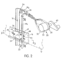
- the window regulator mechanism is shown as incorporated in an automotive vehicle door structure 10 for operating a vertically movable window panel 12.
- the door structure comprises an inner panel 14 formed at its lower portion with a terminal flange over which the marginal portion of an outer panel is crimped to provide an integral structure having a space or well between the inner and outer panels.
- the window well has a slot or access opening through which the window panel 12 is slidably moved into and out of the well by the window regulator mechanism positioned at the inner side of the path of travel of the window panel 12.
- the window regulator mechanism includes a lifter plate 16 engaging the lower portion of the window panel 12.
- a slider member 17 is secured to the lifter plate 16 and mounted for sliding movement along a longitudinal guide rail member 18 bolted on the inner panel 14.
- the guide rail member 18 is preferably steel or aluminum and formed by stamping.
- An actuating mechanism in the form of a drive unit 20 is mounted on the inner panel to aid in unwinding one of two wires W1 and W2 and retracting the other wire so as to vertically move the lifter plate 16 and window panel 12.
- the guide rail member 18 has at its lower end a semi-circular guide plate 22 secured thereon for guiding the wire W1 and at its upper end a guide pulley 24 secured rotatably thereon for guiding the wire W2.
- the vertically spaced-apart guide plate 22 and pulley 24 can be referred to as guiding portions and constitute the limits of movement of the lifter plate 16.
- the guide plate 18 also has a guide opening 26 for guiding the wires W1 and W2 toward the drive unit 20 which is shown schematically as including drive and driven drums 28 and 30 housed within a casing 32.
- the drive drum 28 can be driven in response to manual operation in a conventional fashion by a window crank handle 40 or by an electrically powered motor.
- the slider member 17 has a nipple housing member 34 constructed and arranged to fixedly attach wire beads 36 fixed to the wire or cable W2. This enables the slider member 17 to be slidably driven along guide rail member 18 upon movement of wires W1, W2.
- the wire W1 extends downward from the nipple housing 34 to the semi-circular guide plate 22 around which it extends upward to the pulley 24 and through guide opening 26 and then through a guide tube to the drive drum 28.
- the wire W2 extends upward from the nipple housing 34 to the guide pulley 24 around which it extends to the guide opening 26 and then through a guide tube to the driven drum 30.
- the driven drum 28 rotates in a first or second rotational direction with rotation of the crank handle 40 in a conventional fashion to drive the driven drum 28 and effect movement of the wires W1, W2 through the guide tubes. This in turn causes upwards or downwards vertical movement of the slider member 17 along the guide rail member 18 depending on the direction in which the crank handle 40 is rotated.
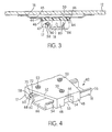
- FIG. 3 there is shown a cross-sectional view of the lifter plate 16, the slider member 17, and the steel guide rail member 18 onto which the slider member 17 is slidably mounted.
- the lifter plate 16 is secured to the window panel 12 in conventional fashion.
- the lifter plate 16 has tab members 44 punched through the metal material thereof, which forms openings 45 in the remaining portions of the lifter plate 16.
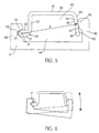
- the tab members 44 are crimped around opposite edges 46 defined by a surface extending between leg portions 48 of the slider member 17 (see Fig. 4).
- the slider member 17 is molded from a plastic material. It is also provided with a plurality (3) of locating projections 50 constructed and arranged to be received to be received in corresponding holes in the lifter plate 16 for proper alignment between the slider member 17 and the lifter plate 16 with the window panel 12 attached thereto.
- the opposite leg portions 48 disposed on an opposite side of the base portion 52 are provided with "V"-shaped grooves 58 defined by a pair of inclined surfaces and which are particularly constructed and arranged to receive a nose portion 60 extending laterally outwardly from the end of a side flange portion 62 opposite the side flange portion 56.
- the side leg portions 48 define a window moving structure channel 49 therebetween.
- the guide rail member 18 includes a longitudinally extending base portion 66, and that the side flange portions 56 and 62 extend outwardly from opposite transverse ends of the base portion 66 to define a guide rail channel 82 therebetween.
- the side flange portion 62 initially extends from the base portion 66 in a generally perpendicular relation to the base portion 66.
- the nose portion 60 of the side flange portion 62 is a folded over end portion and includes a longitudinal strip of metal 68 extending laterally outwardly away from the guide rail channel 82 formed by the steel guide rail member 18, a rounded end region 70, and a longitudinally extending flat portion 72 disposed in overlying relation with respect to the strip 68.
- the end portion 86 of the side flange portion 56 is bent slightly outwardly in an opposite direction from the more proximal portions of the side flange portion 56 in a direction slightly away from the channel 82 to provide a concave exterior surface 85 adjacent the convex exterior surface 84.
- the side flange portion 56 has a slight "S" shaped configuration as viewed in the position shown in Fig. 3 (inverted “S” in Figs. 5 and 6).
- the slider member 17 pivots about fixed pivot axis P by permitting the exterior curved surface 87 of the projecting portions 54 to move in sliding engagement about the circular path defined by the exterior convex surface 84.
- the "V"-shaped groove 58 permits the curved exterior surface 74 of the folded flange portion 60 to be rotatably received therein and pivot about the pivot axis P.
- the concave exterior surface 85 is configured to engage the inwardly facing surfaces 87 of the projecting portions 54 in order to prevent the side leg portion 48 and the side flange portion 56 from moving out of engagement with one another. This function is usually not necessary when the mechanism is installed with the vehicle door, but it is desirable during shipping of the mechanism. Such an arrangement prevents the slider member 17 from becoming separated from the guide rail member 18 and increases assembly efficiency by eliminating the time spent finding and putting together separated components.
- the slider member 17 can be molded together with the lifter plate 16 as an integral window moving structure, incorporating the nipple housing 34 to which the wires W1 and W2 attach.
- the design in accordance with the present invention permits freedom of rotation of the slider member 17 about the pivot axis P to allow for the spiraling action of the rails which are mounted at an angle to the vertical, as can be achieved in other conventionally provided slider/rail designs.
- the inboard/outboard freedom is eliminated by the "V"-shaped groove configuration in conjunction with the curved opposite wall of the guide rail member 1 8 as can be appreciated from the figures. In other words, the relative movement between the guide rail member 18 and the slider member 17 in a radial direction with respect to the pivot axis is substantially prevented.
- the advantages of such a construction are two-fold.
- First of all, the relative pivoting movement of the slider member 17 with respect to the fixed pivot axis P of the guide rail member 18 allows for limited pivotal free play in order to compensate for any irregularities or misalignments which may occur during the machining of the components, installation of the mechanism, or which simply may develop over a period of usage.
- the guide rail member 18 is formed in a roll-forming operation.
- the guide rail member can initially be formed with a symmetric cross-section, and then formed into the provided shape with curving tools and post-forming operations.
- the slider member leg portions 48 need not be resiliently biased inwardly against the side flange portions 56 or 62 to maintain proper engagement. An interference fit without high frictional forces achieved, with zero clearance between the slide member 17 and the guide rail member 18 so as to prevent free play. At the same time. there is a low degree of friction between the slider member 17 and the guide rail member 18 to permit relatively easy movement of the slider member 17 along the guide rail member 18. Resiliently biasing the leg portions 48 against the side flange portions 56, however, is preferred because this allows the slider member 17 to be snap-fit of an intermediate portion of the guide rail member 18 rather than sliding it over an end portion thereof.
- the use of the term snap-fit encompasses the arrangement wherein the window moving structure is slidably mounted on an intermediate portion of the guide rail member by initially engaging the side leg portions with intermediate portions of the side flange portions so that the side leg portions are urged laterally outwardly until the nose-receiving groove reaches the nose portion and the inwardly facing surface of the another side leg portion opposite the nose-receiving groove reaches the convex exterior surface.
- the side leg portions resiliently move inwardly into engagement with the nose portion and the convex exterior surface to thereby realize a snap-fit engagement.
- the counterbalance assembly of the present invention can be used for both conventional cable/drum and arm/sector regulators.
- the window counter balance assembly of the present invention employs an elastic strap member that is intended to replace conventional steel counter balance springs.
- the construction of the present invention is less expensive and offers greater flexibility for operation with variations in window design in comparison with the conventional construction.
Landscapes
- Engineering & Computer Science (AREA)
- Mechanical Engineering (AREA)
- Window Of Vehicle (AREA)
- Power-Operated Mechanisms For Wings (AREA)
- Closing And Opening Devices For Wings, And Checks For Wings (AREA)
Claims (14)
- Fensterhebermechanismus für eine vertikale Bewegung einer innerhalb einer Kraftfahrzeugtür angebrachten Fensterscheibe (12), wobei der Mechanismus umfaßt:ein längsgestrecktes Führungsschienenelement (18), das innerhalb der Fahrzeugtür angebracht ist und sich in Längsrichtung in einer im wesentlichen vertikalen Richtung erstreckt, wobei das Führungsschienenelement (18) einen Basisabschnitt (66) und ein Paar von Seitenflanschabschnitten (56, 62) umfaßt, die sich in Längsrichtung entlang gegenüberliegender Seiten des Basisabschnittes erstrecken, um zwischen sich einen Führungsschienenkanal (82) zu bilden, wobei ein erster des Paares von Seitenflanschabschnitten (62) einen Nasenabschnitt (60) aufweist, der sich von ihm seitlich nach außen erstreckt und ein zweiter des Paares von Seitenflanschabschnitten (56) eine seitlich nach außen zeigende konvexe Außenfläche (84) aufweist;eine Fensterbewegungskonstruktion (16, 17), die an der Fensterscheibe (12) angreift, wobei die Fensterbewegungskonstruktion ein Basiselement (52) und ein Paar von Seitenschenkelabschnitten (48) aufweist, die sich von gegenüberliegenden Seiten des Basiselements zur Bildung eines Fensterbewegungskonstruktionskanals (49) zwischen ihnen erstrecken, wobei einer der Seitenschenkelabschnitte eine Nasenaufnahmenut (58) aufweist, die in seiner nach innen zeigenden Fläche ausgebildet ist, und der andere der Seitenschenkelabschnitte eine nach innen zeigende Fläche (87) aufweist, die der Nasenaufnahmenut entgegengesetzt ist, wobei die Fensterbewegungskonstruktion (16, 17) verschiebbar auf dem Führungsschienenelement (18) angebracht ist, damit die Fensterscheibe (12) vertikal bezüglich der Fahrzeugtür bewegt werden kann; undeinen handbetätigbaren Betätigungsmechanismus (20), der so aufgebaut und angeordnet ist, daß die Fensterbewegungskonstruktion (16, 17) insgesamt vertikal entlang des Führungsschienenelements (18) verschoben werden kann, so daß die Fensterscheibe (12) als Reaktion auf eine manuelle Betätigung insgesamt vertikal bezüglich der Fahrzeugtür bewegt wird,wobei der Nasenabschnitt (60) des Führungsschienenelements (18) innerhalb der Nasenaufnahmenut (58) der Fensterbewegungskonstruktion aufgenommen ist und die konvexe Außenfläche des Führungsschienenelements (18) verschiebbar in die nach innen zeigende Fläche der Fensterbewegungskonstruktion eingreift, dadurch gekennzeichnet, daß (1) eine relative Schwenkbewegung zwischen dem Führungsschienenelement (18) und der Fensterbewegungskonstruktion (16, 17) um eine feste Schwenkachse, die sich in Längsrichtung durch den Nasenabschnitt (60) erstreckt, während einer insgesamt vertikalen Bewegung der Fensterscheibe ermöglicht wird, und (2) eine relative Bewegung zwischen dem Führungsschienenelement (18) und der Fensterbewegungskonstruktion (16, 17) in einer radialen Richtung bezüglich der festen Schwenkachse im wesentlichen eingeschränkt wird, um hierdurch Vibrationen zu verringern, die als Ergebnis einer kräftigen Bewegung der Fahrzeugtür (10) in Schließeingriff mit einer Kraftfahrzeugkarosserie auftreten.
- Fensterhebermechanismus nach Anspruch 1, bei dem die konvexe Außenfläche (84) von einem Bogensegment eines imaginären Kreises gebildet wird, dessen Mittelpunkt mit der festen Schwenkachse übereinstimmt.
- Fensterhebermechanismus nach Anspruch 2, bei dem ein Endabschnitt (86) des zweiten des Paares von Seitenflanschabschnitten (56) eine konkave Außenfläche (85) aufweist, die an die konvexe Außenfläche (84) angrenzt und so ausgebildet ist, daß verhindert wird, daß die nach innen zeigende Fläche des anderen Schenkelabschnittes und der zweite des Paares von Seitenflanschen während einer relativen Schwenkbewegung zwischen dem Führungsschienenelement (18) und der Fensterbewegungskonstruktion (16, 17) aus ihrem gegenseitigem Eingriff bewegt werden, während der Fensterhebermechanismus versandt wird, um hierdurch zu verhindern, daß das Führungsschienenelement (18) und die Fensterbewegungskonstruktion (16, 17) voneinander getrennt werden, bevor sie in die Fahrzeugtür eingebaut werden.
- Fensterhebermechanismus nach Anspruch 1, 2 oder 3, bei dem der Nasenabschnitt (60) ein gefalteter Endabschnitt des ersten des Paares der Seitenflanschabschnitte ist.
- Fensterhebermechanismus nach Anspruch 1, 2 oder 3, bei dem die Nasenaufnahmenut (58) eine V-förmige Nasenaufnahmenut ist, die von einem Paar von geneigten Flächen gebildet wird, die sich miteinander schneiden.
- Fensterhebermechanismus nach Anspruch 2, 3, 4 oder 5, bei dem ein seitlich äußerster Abschnitt des Nasenabschnitts (60) abgerundet ist,wobei der Nasenaufnahmekanal eine V-förmige Nasenaufnahmenut (58) ist, die von einem Paar geneigter Flächen gebildet wird, die sich miteinander schneiden, undder Nasenabschnitt (60) innerhalb der V-förmigen Nasenaufnahmenut (58) so aufgenommen ist, daß der abgerundete, seitlich äußerste Abschnitt des Nasenabschnittes in die geneigten Flächen der V-förmigen Nasenaufnahmenut eingreift.
- Fensterhebermechanismus nach Anspruch 1 oder 6, bei dem die Seitenschenkelabschnitte (48) der Fensterbewegungskonstruktion nach innen gegen das Paar von Seitenflanschabschnitten (56, 62) des Führungsschienenelementes (18) vorgespannt sind.
- Fensterhebermechanismus nach Anspruch 1 oder 6, bei dem die Fensterbewegungskonstruktion (16, 17) mittels eines Preßsitzes verschiebbar an dem Führungsschnienenelement (18) angebracht ist.
- Fensterhebermechanismus nach Anspruch 1, 6, 7 oder 8, bei dem die Fensterbewegungskonstruktion umfaßt:ein Schieberelement (17), das verschiebbar an dem Führungsschienenelement (18) angebracht ist, wobei das Basiselement (52) und die Schenkelabschnitte (48) der Fensterbewegungskonstruktion das Schieberelement umfassen; undeine mit der Fensterscheibe (12) in Eingriff stehende und fest an dem Schieberelement (17) angebrachte Hebeplatte (16), damit die Fensterscheibe (12) bezüglich der Fahrzeugtür vertikal bewegt werden kann, wenn das Schieberelement (17) vertikal entlang des Führungsschienenelements gleitet.
- Fensterhebermechanismus nach Anspruch 9, bei dem die Schenkelabschnitte der Fensterbewegungskonstruktion ein Paar von Schenkabschnitten umfassen (48), die sich von jeder Seite des Schieberelements (17) erstrecken.
- Fensterheberechanismus nach Anspruch 1, 6 oder 9, bei dem der Betätigungsmechanismus umfaßt:einen ersten Draht (W1), der an der Fensterbewegungskonstruktion angebracht ist und sich davon nach oben erstreckt;einen zweiten Draht (W2), der an der Fensterbewegungskonstruktion angebracht ist und sich von dieser nach unten erstreckt,wobei der erste und der zweite Draht mit Führungsabschnitten (22, 24) in Eingriff stehen, die in vertikaler Abstandsbeziehung zueinander an dem Führungsschienenelement (18) angeordnet sind,wobei der erste und der zweite Draht über eine angetriebene Trommel (30) gewunden sind, so daß eine Drehung der angetriebenen Trommel (30) in einer ersten Drehrichtung den ersten Draht zurückzieht und die Fensterscheibe (12) vertikal nach oben bezüglich der Fahrzeugtür bewegt, und eine Drehung der angetriebenen Trommel (30) in einer zweiten Drehrichtung den zweiten Draht zurückzieht und die Fensterscheibe (12) vertikal nach unten bezüglich der Fahrzeugtür bewegt.
- Fensterhebermechanismus nach Anspruch 11, bei dem die angetriebene Trommel (30) ansprechend auf eine manuelle Bewegung einer Handkurbel (40) gedreht wird.
- Fensterhebermechanismuns nach Anspruch 1, 6, 9 oder 11, bei dem die nach innen zeigende Fläche (87) des anderen der Seitenschenkelabschnitte der Fensterbewegungskonstruktion eine abgerundete Ausbildung hat.
- Fensterhebermechanismus nach Anspruch 1, 6, 9 oder 11, bei dem die Fensterbewegungskonstruktion verschiebbar an einem Zwischenabschnitt des Führungsschienenelements (18) angebracht ist, indem zunächst die Seitenschenkelabschnitte mit Zwischenabschnitten der Seitenflanschabschnitte so in Eingriff gebracht werden, daß die Seitenschenkelabschnitte seitlich nach außen gedrückt werden bis die Nasenaufnahmenut (58) den Nasenabschnitt (60) erreicht und die nach innen zeigende Fläche (87) des anderen Seitenschenkelabschnitts gegenüber der Nasenaufnahmenut die konvexe Außenfläche (84) erreicht, wobei die Seitenschenkelabschnitte sich elastisch nach innen in Eingriff mit den Nasenabschnitten (60) und der konvexen Außenfläche bewegen, um hierdurch einen Schnappbefestigungseingriff zu realisieren.
Applications Claiming Priority (3)
| Application Number | Priority Date | Filing Date | Title |
|---|---|---|---|
| US4569897P | 1997-05-06 | 1997-05-06 | |
| US45698P | 1997-05-06 | ||
| PCT/CA1998/000422 WO1998050659A1 (en) | 1997-05-06 | 1998-05-06 | Window regulator mechanism |
Publications (2)
| Publication Number | Publication Date |
|---|---|
| EP0980458A1 EP0980458A1 (de) | 2000-02-23 |
| EP0980458B1 true EP0980458B1 (de) | 2001-03-07 |
Family
ID=21939388
Family Applications (2)
| Application Number | Title | Priority Date | Filing Date |
|---|---|---|---|
| EP98919007A Expired - Lifetime EP0980457B1 (de) | 1997-05-06 | 1998-05-06 | Fensterheberanordnung mit gewichtsausgleich |
| EP98919008A Expired - Lifetime EP0980458B1 (de) | 1997-05-06 | 1998-05-06 | Fensterhebermechanismus |
Family Applications Before (1)
| Application Number | Title | Priority Date | Filing Date |
|---|---|---|---|
| EP98919007A Expired - Lifetime EP0980457B1 (de) | 1997-05-06 | 1998-05-06 | Fensterheberanordnung mit gewichtsausgleich |
Country Status (8)
| Country | Link |
|---|---|
| US (2) | US6052947A (de) |
| EP (2) | EP0980457B1 (de) |
| AT (2) | ATE199578T1 (de) |
| AU (2) | AU7202298A (de) |
| BR (2) | BR9809224A (de) |
| CA (2) | CA2289255A1 (de) |
| DE (2) | DE69800576T2 (de) |
| WO (2) | WO1998050659A1 (de) |
Cited By (1)
| Publication number | Priority date | Publication date | Assignee | Title |
|---|---|---|---|---|
| CN107288477A (zh) * | 2016-04-13 | 2017-10-24 | 恩坦华产品法国公司 | 用于窗调节器的装置和方法 |
Families Citing this family (35)
| Publication number | Priority date | Publication date | Assignee | Title |
|---|---|---|---|---|
| DE19654851C1 (de) * | 1996-12-30 | 1998-06-10 | Brose Fahrzeugteile | Seilfensterheber mit einer Führungsschiene |
| DE19838347C2 (de) * | 1998-08-14 | 2000-05-31 | Brose Fahrzeugteile | Führungsschiene und Verfahren zur Herstellung einer Führungsschiene für einen Seil- oder Bowdenrohr-Fensterheber |
| US6609334B1 (en) * | 1998-10-15 | 2003-08-26 | Kuster Automotive Door Systems Gmbh | Cable-operated window lifting mechanism with lateral displacement compensation |
| US6260905B1 (en) * | 2000-01-04 | 2001-07-17 | Michael T. Wagner | Multi-segment, vertically operable, rear vehicle window |
| US6415550B1 (en) * | 2000-02-04 | 2002-07-09 | Meritor Light Vehicle Systems, Inc. | Integral linear motor |
| US6430873B1 (en) * | 2000-03-08 | 2002-08-13 | Atoma International Corporation | Dual drum and rail window regulator drive system |
| AU2001253668A1 (en) | 2000-04-19 | 2001-11-07 | Ashland Products, Inc. | Balance system for sash window assembly |
| FR2811367B1 (fr) * | 2000-07-04 | 2003-02-14 | Meritor Light Vehicle Sys Ltd | Leve-vitre ayant un curseur a deplacement silencieux |
| GB0030097D0 (en) * | 2000-12-09 | 2001-01-24 | Meritor Light Vehicle Sys Ltd | Assembly |
| JP3993105B2 (ja) * | 2001-01-19 | 2007-10-17 | マグナ クロージャーズ インコーポレイテッド | ウインドウレギュレータ |
| FR2820451B1 (fr) * | 2001-02-06 | 2003-08-29 | Meritor Light Vehicle Sys Ltd | Curseur de leve-vitre pour vitre coulissante |
| DE60220548T2 (de) * | 2002-04-03 | 2008-02-07 | Grupo Antolín-Ingeniería S.A. | Leichter fensterheber für fahrzeuge |
| ES1052188Y (es) * | 2002-06-06 | 2003-03-16 | Castellon Melchor Daumal | Perfil para carriles de material plastico para elevalunas de automoviles. |
| DE20210370U1 (de) * | 2002-07-01 | 2002-08-29 | SAI Automotive SAL GmbH, 76744 Wörth | Umlenkrolleneinrichtung |
| US6910730B2 (en) * | 2002-12-25 | 2005-06-28 | Shiroki Corporation | Mounting device for mounting a cable-operated window regulator |
| DE10335285A1 (de) * | 2003-07-28 | 2005-03-03 | Sai Automotive Sal Gmbh | Seilumlenkung für eine Fensterhebevorrichtung |
| DE10361414A1 (de) * | 2003-12-22 | 2005-07-14 | Brose Fahrzeugteile Gmbh & Co. Kg, Coburg | Fensterhebersystem mit wahlweise einsetzbarer manueller oder motorischer Antriebseinrichtung |
| US7694460B2 (en) * | 2004-07-16 | 2010-04-13 | Agc Automotive Americas R & D, Inc. | Tuned window sash |
| US7213370B2 (en) * | 2004-09-01 | 2007-05-08 | Dura Global Technologies, Inc. | Window regulator |
| WO2006045187A1 (en) * | 2004-10-26 | 2006-05-04 | Magna Closures Inc. | Locking lift plate |
| DE102004063514A1 (de) * | 2004-12-27 | 2006-07-06 | Brose Fahrzeugteile Gmbh & Co. Kommanditgesellschaft, Coburg | Fensterscheibe für ein Kraftfahrzeug |
| EP1717080A1 (de) * | 2005-04-28 | 2006-11-02 | Inalfa Roof Systems Group B.V. | Führungsvorrichtung |
| JP4727547B2 (ja) * | 2006-10-11 | 2011-07-20 | 三井金属アクト株式会社 | 車両用ウインドウレギュレータ装置 |
| DE102010031013A1 (de) * | 2010-07-06 | 2012-01-12 | Brose Fahrzeugteile Gmbh & Co. Kommanditgesellschaft, Hallstadt | Kraftfahrzeug-Fensterheber |
| DE202010012567U1 (de) * | 2010-09-08 | 2011-12-12 | Brose Fahrzeugteile Gmbh & Co. Kommanditgesellschaft, Hallstadt | Seilumlenkstück für einen Seilfensterheber |
| JP6346046B2 (ja) * | 2014-09-18 | 2018-06-20 | 株式会社ハイレックスコーポレーション | 取付構造 |
| JP6835524B2 (ja) * | 2016-10-05 | 2021-02-24 | 株式会社城南製作所 | ウインドレギュレータ及びウインドレギュレータを備えた車両用ドア |
| JP2019031816A (ja) * | 2017-08-07 | 2019-02-28 | 株式会社ハイレックスコーポレーション | 窓ガラス昇降装置 |
| JP6739476B2 (ja) * | 2018-06-29 | 2020-08-12 | 株式会社ハイレックスコーポレーション | ケーブル配索構造およびこれを用いた窓ガラス昇降装置 |
| JP7187980B2 (ja) * | 2018-10-29 | 2022-12-13 | 株式会社アイシン | ウインドレギュレータ及びその組付方法 |
| JP7146357B2 (ja) * | 2020-07-20 | 2022-10-04 | 株式会社城南製作所 | ウインドレギュレータ |
| WO2022094276A1 (en) * | 2020-10-30 | 2022-05-05 | Inteva Products, Llc | Window regulator with optimized motor configuration |
| JP7013614B1 (ja) * | 2021-08-10 | 2022-01-31 | 株式会社城南製作所 | ウインドレギュレータ |
| DE202023100990U1 (de) | 2022-03-03 | 2023-03-21 | Inteva Products, Llc | Fensterheber für ein rahmenloses System |
| JP7789635B2 (ja) * | 2022-07-28 | 2025-12-22 | 株式会社ハイレックスコーポレーション | キャリアプレートおよびウインドレギュレータ |
Family Cites Families (38)
| Publication number | Priority date | Publication date | Assignee | Title |
|---|---|---|---|---|
| US1461277A (en) * | 1923-07-10 | Sash raising and lowering device | ||
| US649729A (en) * | 1899-09-01 | 1900-05-15 | William Lowrie Isbills | Curtain-holder. |
| US1617195A (en) * | 1923-06-28 | 1927-02-08 | Studebaker Corp | Window regulator |
| US1557150A (en) * | 1923-07-09 | 1925-10-13 | E D Moon | Window-control mechanism |
| US1651003A (en) * | 1923-08-27 | 1927-11-29 | Harry M Tichenor | Window-control mechanism |
| US1622603A (en) * | 1923-08-27 | 1927-03-29 | Dura Co | Mounting for window-control mechanism |
| US1535987A (en) * | 1923-09-24 | 1925-04-28 | Toledo Automotive Products Com | Window-control mechanism |
| US1710220A (en) * | 1923-11-05 | 1929-04-23 | Briggs Mfg Co | Lock board |
| US2076938A (en) * | 1935-08-07 | 1937-04-13 | Edwin M Bailey | Automatic automobile window elevating mechanism and lock |
| DE735400C (de) * | 1939-09-19 | 1943-05-21 | Heinz Wernher Eckert Greifendo | Vorrichtung zum wahlweisen Verstellen des Schiebefensters und OEffnen des Tuerriegels an Kraftfahrzeugen u. dgl. |
| US2276512A (en) * | 1941-02-28 | 1942-03-17 | John B Parsons | Rear quarter window operator |
| US2657925A (en) * | 1946-03-27 | 1953-11-03 | Crow Rector | Closure, operating, and controlling device |
| GB819614A (en) * | 1957-08-19 | 1959-09-09 | Daimler Benz Ag | Improvements relating to window opening and closing mechanism |
| US4001971A (en) * | 1975-09-02 | 1977-01-11 | Freedland Industries Corporation | Unit window regulator assembly |
| US4117568A (en) * | 1977-01-07 | 1978-10-03 | Robin Products Company | Crank handle for window regulator shaft |
| US4441276A (en) * | 1980-07-26 | 1984-04-10 | Nissan Motor Co., Ltd. | Window regulating device for a window glass of a vehicle door or the like |
| US4400913A (en) * | 1981-06-15 | 1983-08-30 | Chrysler Corporation | Counterbalance pinion for vehicle window regulator |
| JPS58123986A (ja) * | 1982-01-19 | 1983-07-23 | 株式会社城南製作所 | 自動車用ウインドレギユレ−タの窓ガラス案内装置 |
| US4502247A (en) * | 1982-02-23 | 1985-03-05 | Nippon Cable System Inc. | Guide rail for a window regulator and slide guide mechanism employing the same |
| JPS605986A (ja) * | 1983-06-25 | 1985-01-12 | 日産自動車株式会社 | ウインドウレギユレ−タ |
| IT1196321B (it) * | 1984-01-20 | 1988-11-16 | Nippon Cable System Inc | Dispositivo di azionamento impiegato in un regolatore di finestra |
| JPH0345850Y2 (de) * | 1984-10-25 | 1991-09-27 | ||
| DE3600413A1 (de) * | 1986-01-09 | 1987-07-16 | Rockwell Golde Gmbh | Scheibenfuehrung fuer ein in den fensterschacht eines fahrzeuges versenkbares schiebefenster |
| JPH0316862Y2 (de) * | 1987-01-16 | 1991-04-10 | ||
| CA1297928C (en) * | 1987-03-18 | 1992-03-24 | Nebojsa Djordjevic | Cable window regulator |
| US4779380A (en) * | 1987-06-05 | 1988-10-25 | Caldwell Manufacturing Company | Spring cover friction system for sash balance |
| JPH0676009B2 (ja) * | 1988-01-25 | 1994-09-28 | マツダ株式会社 | 自動車のガラス構造 |
| US4854558A (en) * | 1988-07-07 | 1989-08-08 | Caldwell Manufacturing Company | Sound deadener for window counterbalance spring |
| US4882805A (en) * | 1988-12-12 | 1989-11-28 | General Motor Corporation | Slider for window regulator arm |
| JPH0725420Y2 (ja) * | 1989-07-17 | 1995-06-07 | 日本ケーブル・システム株式会社 | ウインドレギュレータ用摺動部材 |
| US5205074A (en) * | 1990-11-28 | 1993-04-27 | Andersen Corporation | Counterbalanced window operators |
| US5490354A (en) * | 1991-09-16 | 1996-02-13 | Brose Fahrezeugteile Gmbh & Co. Kommanditgesellschaft | Cable mechanism for raising and lowering windows of motor vehicles |
| US5267416A (en) * | 1992-07-15 | 1993-12-07 | Caldwell Manufacturing Company | Window sash counterbalance with varying lift |
| US5201144A (en) * | 1992-09-14 | 1993-04-13 | General Motors Corporation | Eccentrically located aperture in a cam slider for window regulator |
| US5325631A (en) * | 1993-03-25 | 1994-07-05 | A.L. Hansen Mfg. Co. | Window regulator |
| FR2704267A1 (fr) * | 1993-04-19 | 1994-10-28 | Dupre Jacques | Dispositif d'équilibrage en déplacement des portes de garage et similaires en vue de réduire les efforts d'ouverture ou de fermeture. |
| US5469663A (en) * | 1994-11-04 | 1995-11-28 | Chrysler Corporation | Snap-in attachment of window pane lift plate to window regulator |
| US5623785A (en) * | 1995-09-29 | 1997-04-29 | Excel Industries, Inc. | Window regulator with torsion spring actuated direct cable tensioning |
-
1998
- 1998-05-06 AT AT98919008T patent/ATE199578T1/de not_active IP Right Cessation
- 1998-05-06 AU AU72022/98A patent/AU7202298A/en not_active Abandoned
- 1998-05-06 EP EP98919007A patent/EP0980457B1/de not_active Expired - Lifetime
- 1998-05-06 CA CA002289255A patent/CA2289255A1/en not_active Abandoned
- 1998-05-06 US US09/073,355 patent/US6052947A/en not_active Expired - Fee Related
- 1998-05-06 EP EP98919008A patent/EP0980458B1/de not_active Expired - Lifetime
- 1998-05-06 WO PCT/CA1998/000422 patent/WO1998050659A1/en not_active Ceased
- 1998-05-06 BR BR9809224-3A patent/BR9809224A/pt not_active Application Discontinuation
- 1998-05-06 US US09/073,351 patent/US5970658A/en not_active Expired - Fee Related
- 1998-05-06 AU AU72021/98A patent/AU7202198A/en not_active Abandoned
- 1998-05-06 CA CA002289256A patent/CA2289256A1/en not_active Abandoned
- 1998-05-06 WO PCT/CA1998/000421 patent/WO1998050656A1/en not_active Ceased
- 1998-05-06 BR BR9809595-1A patent/BR9809595A/pt not_active Application Discontinuation
- 1998-05-06 AT AT98919007T patent/ATE214774T1/de not_active IP Right Cessation
- 1998-05-06 DE DE69800576T patent/DE69800576T2/de not_active Expired - Fee Related
- 1998-05-06 DE DE69804296T patent/DE69804296T2/de not_active Expired - Fee Related
Cited By (2)
| Publication number | Priority date | Publication date | Assignee | Title |
|---|---|---|---|---|
| CN107288477A (zh) * | 2016-04-13 | 2017-10-24 | 恩坦华产品法国公司 | 用于窗调节器的装置和方法 |
| CN107288477B (zh) * | 2016-04-13 | 2021-08-03 | 恩坦华产品法国公司 | 用于窗调节器的装置和方法 |
Also Published As
| Publication number | Publication date |
|---|---|
| AU7202198A (en) | 1998-11-27 |
| WO1998050656A1 (en) | 1998-11-12 |
| DE69800576T2 (de) | 2001-09-27 |
| DE69804296T2 (de) | 2002-11-07 |
| AU7202298A (en) | 1998-11-27 |
| EP0980457A1 (de) | 2000-02-23 |
| DE69800576D1 (de) | 2001-04-12 |
| ATE214774T1 (de) | 2002-04-15 |
| BR9809224A (pt) | 2000-07-04 |
| EP0980457B1 (de) | 2002-03-20 |
| US6052947A (en) | 2000-04-25 |
| US5970658A (en) | 1999-10-26 |
| DE69804296D1 (de) | 2002-04-25 |
| CA2289255A1 (en) | 1998-11-12 |
| EP0980458A1 (de) | 2000-02-23 |
| ATE199578T1 (de) | 2001-03-15 |
| WO1998050659A1 (en) | 1998-11-12 |
| CA2289256A1 (en) | 1998-11-12 |
| BR9809595A (pt) | 2000-07-04 |
Similar Documents
| Publication | Publication Date | Title |
|---|---|---|
| US5970658A (en) | Window regulator mechanism | |
| US5505022A (en) | Window regulator | |
| US6088965A (en) | Door window regulator | |
| US5018243A (en) | Vehicle door hinge with compound roller structure | |
| JPS62164977A (ja) | 固定部材に対する可動部材の相対位置を選定する装置 | |
| US5101596A (en) | Downstop for window regulator | |
| US4095370A (en) | Band-type window regulator for vehicles | |
| US4654931A (en) | Hinge device with brake spring for tilting windows | |
| US5784832A (en) | Self aligning window regulator | |
| US6279269B1 (en) | Window regulator for a vehicle | |
| US5294097A (en) | Apparatus for mounting a spiral spring | |
| CN214403137U (zh) | 预组装式铰链模块及铰接系统 | |
| KR960016478B1 (ko) | 자동차용 도어힌지 | |
| CN211315239U (zh) | 排气阀 | |
| GB2236799A (en) | Improvements in or relating to friction-stay hinges | |
| US3345680A (en) | Friction type automobile door hold-open means | |
| EP0980459B1 (de) | Fensterheber mit einer verbesserten kurbeleinheit | |
| US20070101653A1 (en) | Hinge assembly for casement windows | |
| CA2059600C (en) | Twist lock window regulator pivot pin | |
| US3842541A (en) | Window regulator mechanism for a vehicle | |
| JPH0334466Y2 (de) | ||
| CN215108236U (zh) | 极窄门免打孔防摆轮 | |
| KR200337395Y1 (ko) | 안전성 및 내구성이 향상된 힌지 일체형 자동차 도어 체커 | |
| KR20040050182A (ko) | 도어체커 | |
| KR200168052Y1 (ko) | 자동차의 도어 체크링크 |
Legal Events
| Date | Code | Title | Description |
|---|---|---|---|
| PUAI | Public reference made under article 153(3) epc to a published international application that has entered the european phase |
Free format text: ORIGINAL CODE: 0009012 |
|
| 17P | Request for examination filed |
Effective date: 19991203 |
|
| AK | Designated contracting states |
Kind code of ref document: A1 Designated state(s): AT DE FR GB IT SE |
|
| GRAG | Despatch of communication of intention to grant |
Free format text: ORIGINAL CODE: EPIDOS AGRA |
|
| 17Q | First examination report despatched |
Effective date: 20000629 |
|
| GRAG | Despatch of communication of intention to grant |
Free format text: ORIGINAL CODE: EPIDOS AGRA |
|
| GRAH | Despatch of communication of intention to grant a patent |
Free format text: ORIGINAL CODE: EPIDOS IGRA |
|
| GRAH | Despatch of communication of intention to grant a patent |
Free format text: ORIGINAL CODE: EPIDOS IGRA |
|
| GRAA | (expected) grant |
Free format text: ORIGINAL CODE: 0009210 |
|
| AK | Designated contracting states |
Kind code of ref document: B1 Designated state(s): AT DE FR GB IT SE |
|
| REF | Corresponds to: |
Ref document number: 199578 Country of ref document: AT Date of ref document: 20010315 Kind code of ref document: T |
|
| REF | Corresponds to: |
Ref document number: 69800576 Country of ref document: DE Date of ref document: 20010412 |
|
| ITF | It: translation for a ep patent filed | ||
| ET | Fr: translation filed | ||
| REG | Reference to a national code |
Ref country code: GB Ref legal event code: IF02 |
|
| PLBE | No opposition filed within time limit |
Free format text: ORIGINAL CODE: 0009261 |
|
| STAA | Information on the status of an ep patent application or granted ep patent |
Free format text: STATUS: NO OPPOSITION FILED WITHIN TIME LIMIT |
|
| 26N | No opposition filed | ||
| PGFP | Annual fee paid to national office [announced via postgrant information from national office to epo] |
Ref country code: GB Payment date: 20020501 Year of fee payment: 5 |
|
| PGFP | Annual fee paid to national office [announced via postgrant information from national office to epo] |
Ref country code: AT Payment date: 20020508 Year of fee payment: 5 |
|
| PGFP | Annual fee paid to national office [announced via postgrant information from national office to epo] |
Ref country code: SE Payment date: 20020513 Year of fee payment: 5 |
|
| PGFP | Annual fee paid to national office [announced via postgrant information from national office to epo] |
Ref country code: FR Payment date: 20020529 Year of fee payment: 5 |
|
| PGFP | Annual fee paid to national office [announced via postgrant information from national office to epo] |
Ref country code: DE Payment date: 20020730 Year of fee payment: 5 |
|
| PG25 | Lapsed in a contracting state [announced via postgrant information from national office to epo] |
Ref country code: GB Free format text: LAPSE BECAUSE OF NON-PAYMENT OF DUE FEES Effective date: 20030506 Ref country code: AT Free format text: LAPSE BECAUSE OF NON-PAYMENT OF DUE FEES Effective date: 20030506 |
|
| PG25 | Lapsed in a contracting state [announced via postgrant information from national office to epo] |
Ref country code: SE Free format text: LAPSE BECAUSE OF NON-PAYMENT OF DUE FEES Effective date: 20030507 |
|
| PG25 | Lapsed in a contracting state [announced via postgrant information from national office to epo] |
Ref country code: DE Free format text: LAPSE BECAUSE OF NON-PAYMENT OF DUE FEES Effective date: 20031202 |
|
| GBPC | Gb: european patent ceased through non-payment of renewal fee |
Effective date: 20030506 |
|
| EUG | Se: european patent has lapsed | ||
| PG25 | Lapsed in a contracting state [announced via postgrant information from national office to epo] |
Ref country code: FR Free format text: LAPSE BECAUSE OF NON-PAYMENT OF DUE FEES Effective date: 20040130 |
|
| REG | Reference to a national code |
Ref country code: FR Ref legal event code: ST |
|
| PG25 | Lapsed in a contracting state [announced via postgrant information from national office to epo] |
Ref country code: IT Free format text: LAPSE BECAUSE OF NON-PAYMENT OF DUE FEES Effective date: 20050506 |