EP0980461B1 - Richtungsbohrgerät - Google Patents
Richtungsbohrgerät Download PDFInfo
- Publication number
- EP0980461B1 EP0980461B1 EP98923228A EP98923228A EP0980461B1 EP 0980461 B1 EP0980461 B1 EP 0980461B1 EP 98923228 A EP98923228 A EP 98923228A EP 98923228 A EP98923228 A EP 98923228A EP 0980461 B1 EP0980461 B1 EP 0980461B1
- Authority
- EP
- European Patent Office
- Prior art keywords
- drill
- drilling unit
- directional
- extendable
- directional drilling
- Prior art date
- Legal status (The legal status is an assumption and is not a legal conclusion. Google has not performed a legal analysis and makes no representation as to the accuracy of the status listed.)
- Expired - Lifetime
Links
- 238000005553 drilling Methods 0.000 title claims abstract description 107
- 238000000034 method Methods 0.000 claims description 5
- 239000007787 solid Substances 0.000 claims description 3
- 230000003019 stabilising effect Effects 0.000 claims 8
- 239000003381 stabilizer Substances 0.000 description 7
- XLYOFNOQVPJJNP-UHFFFAOYSA-N water Substances O XLYOFNOQVPJJNP-UHFFFAOYSA-N 0.000 description 5
- 244000208734 Pisonia aculeata Species 0.000 description 3
- 230000008859 change Effects 0.000 description 3
- 238000005516 engineering process Methods 0.000 description 2
- 230000009471 action Effects 0.000 description 1
- 230000008901 benefit Effects 0.000 description 1
- 230000005540 biological transmission Effects 0.000 description 1
- 238000004891 communication Methods 0.000 description 1
- 238000010276 construction Methods 0.000 description 1
- 239000002173 cutting fluid Substances 0.000 description 1
- 230000000694 effects Effects 0.000 description 1
- 238000007667 floating Methods 0.000 description 1
- 239000012530 fluid Substances 0.000 description 1
- 238000012423 maintenance Methods 0.000 description 1
- 239000000463 material Substances 0.000 description 1
- 230000007246 mechanism Effects 0.000 description 1
- 238000012544 monitoring process Methods 0.000 description 1
- 230000008569 process Effects 0.000 description 1
- 238000009987 spinning Methods 0.000 description 1
- 238000005406 washing Methods 0.000 description 1
Images


Classifications
-
- E—FIXED CONSTRUCTIONS
- E21—EARTH OR ROCK DRILLING; MINING
- E21B—EARTH OR ROCK DRILLING; OBTAINING OIL, GAS, WATER, SOLUBLE OR MELTABLE MATERIALS OR A SLURRY OF MINERALS FROM WELLS
- E21B19/00—Handling rods, casings, tubes or the like outside the borehole, e.g. in the derrick; Apparatus for feeding the rods or cables
- E21B19/08—Apparatus for feeding the rods or cables; Apparatus for increasing or decreasing the pressure on the drilling tool; Apparatus for counterbalancing the weight of the rods
-
- E—FIXED CONSTRUCTIONS
- E21—EARTH OR ROCK DRILLING; MINING
- E21B—EARTH OR ROCK DRILLING; OBTAINING OIL, GAS, WATER, SOLUBLE OR MELTABLE MATERIALS OR A SLURRY OF MINERALS FROM WELLS
- E21B7/00—Special methods or apparatus for drilling
- E21B7/02—Drilling rigs characterised by means for land transport with their own drive, e.g. skid mounting or wheel mounting
-
- E—FIXED CONSTRUCTIONS
- E21—EARTH OR ROCK DRILLING; MINING
- E21B—EARTH OR ROCK DRILLING; OBTAINING OIL, GAS, WATER, SOLUBLE OR MELTABLE MATERIALS OR A SLURRY OF MINERALS FROM WELLS
- E21B7/00—Special methods or apparatus for drilling
- E21B7/04—Directional drilling
Definitions
- This invention relates to directional drilling apparatus, in particular but not solely to directional drilling apparatus which can be used in confined spaces or utilised in locations close to obstacles such as fences, houses, buildings, etc.
- Directional drilling (also referred to as boring, thrusting and horizontal drilling) is a technology which allows services such as power cables, ducts, water pipes, gas lines, drainage pipes, etc, to be placed underground without the need to cut open the ground surface as is required in cut and cover methods.
- the drill gains its directional ability through the use of an angled steering blade on the drill head.
- a transmitter Immediately behind the drill head is a transmitter (sonde) which relays information to an above ground operator, such information may include how deep the drill head is, the direction in which the drill is heading and the orientation of the drill head such as the angle it is pointing up or down.
- Such devices are normally bulky and incorporate means to rotate and push forward or advance the drill head to as well means rotate it. It is also known to provide means to extend the drill such as a set of rods which are screwed into each other to provide additional length to the drill.
- the power requirement of such a device is somewhat high and as these devices incorporate the source of power the devices are large. This limits the use of the device in that it is common for drilling to be required substantially horizontally or parallel to the surface of the ground from a distance beneath the surface of the ground.
- the drill since the above-mentioned device must rest on ground level the drill must be angled in from the surface of the ground such that it levels off at the required depth.
- the drills as aforementioned are of course flexible to some degree however flexibility is limited therefore the angle at which the drill enters the ground dictates that the drilling unit itself must be positioned at some distance back from the point at which the level drilling commences. Obviously this is inconvenient and may in some cases limit drilling. It may in other cases mean that neighbouring land must be encroached upon and as the ultimate length of the drill usable by such a device is limited the length of useful drilling may be somewhat limited.
- EP-A-0223575 describes a drilling unit mountable to a boom for limited pivoting movement relative to the boom.
- US patent 5226488 describes a directional drilling apparatus in which a drill is mounted on a turret on a vehicle chassis, so that the drill may be rotated in azimuth and tilted downwardly to launch the drill obliquely into the ground.
- US patent 5709276 describes a directional drilling apparatus for launching a directional drill obliquely into the ground in a number of different azimuth directions using a single launch pit.
- German patent publication DE 19732532 describes a directional drilling apparatus in which a directional drill is launched obliquely into the ground from a vehicle, the drill being advanced with rotation in order to proceed along a straight path, and being an advanced without rotation but with vibration of the drill string in order to alter the drilling direction.
- the present invention consists in a directional drilling unit as defined in claim 1.
- Preferably means are provided to monitor the location of said directional drill head, and said means are provided to monitor the orientation (and hence advancement direction when not rotating) of the directional drill head.
- prime mover or power source is a digger or excavator.
- said directional drilling unit is powered by said prime mover, most preferably by power transferred by hydraulic means.
- the present invention may broadly be said to consist in directional drilling apparatus as defined in claim 9.
- said powering of said directional drilling apparatus is from a prime mover such as a digger or excavator.
- said directional drilling apparatus are articulated from said prime mover.
- Preferably said means are provided to monitor the orientation and hence advancement direction when not rotating of the directional drill head.
- actuating means are provided to enable the sideways cant of the drilling apparatus to be adjusted by a user.
- actuating means are mounted on or adjacent said means to rotate said extendable drill, said actuating means oriented such that when actuated a thrust is provided in the forward direction, that is in a direction towards the drill head; and second actuating means are provided, said second actuating means being attachable to said extendable drill and capable of providing a forward thrust to said extendable drill; characterised in that the drill head is advanced in the following manner, first and second actuating means are placed in a non-actuated state; the actuating means are then placed in a state of actuation; thereafter said second actuating means are placed in a state of actuation, thereafter said actuating means returned to a state of non-actuation.
- said actuation means comprises a pair of actuating devices substantially parallel to each other.
- said actuation means and said second actuation means comprise a hydraulic ram.
- said second actuation means includes means to selectively hold said drill and thereby thrust forward.
- Preferred forms of the present invention provide a directional drilling unit 1 said directional drilling unit is articulated by an arm 3 from a prime mover or other source of power 2.
- the source of power or prime mover 2 is preferably but not necessarily easily moveable.
- the prime mover 2 provides power and perhaps control of the directional drilling unit 1 and in preferred forms the power is provided by means of a hydraulic circuit or connection. Such connections will be obvious to those skilled in the art to which the invention relates.
- the unit itself comprises means 30 to rotate the drill rod 7.
- Such means may comprise a hydraulic motor and may incorporate jaws or clamping devices which hold the outer surface of the drill rod 7.
- the directional drilling ability of a drill is achieved through the use of an angled steering blade on the drill head.
- a transmitter relays information to the operator above ground. Information transmitted may consist of a variety of types such as how deep the drill head is, the direction in which it is heading, the orientation, ie angle up or down of the drill head. This information is used by the operator to steer or control the drill. For example if the operator requires the drill to steer to the right to avoid an existing underground service the aboveground locator operator would instruct the drill operator to rotate the drill head to 3 o'clock and push (thrust) the drill head forward which will cause the drill to flex and head to the right.
- the drill operator spins or rotates (a combination of pushing and rotating) the required distance until another change of direction is required.
- the use of a combination of spinning and pushing or thrusting and rotating makes it possible to steer under, over or around obstacles and arrive at the desired end point with a great deal of accuracy.
- the level of accuracy is of course dependant upon the ground conditions encountered.
- the drill head Once the drill head is at its end point, for example drilling may have occurred from one side of the road to the other, the drill head would ordinarily be removed and a cutter and/or packer attached to the drill or drill pipe or string with the service, for example power cable, duct, water pipe, gas line or drainage pipe attached.
- the drill or drill rods would then be pulled out of the ground while the drill is rotating, thus giving the cutter and/or packer a cutting action in allowing a hole of sufficient diameter to be formed for the pipe or cable duct line or service to be installed.
- Preferred forms of the present invention can be used in particular in residential areas where the distance required to be drilled is often no more than 100 metres. Access to the site is often difficult and it is quite often the case that there is no lead-in room. That is, it is often not possible to move a great distance back from the initial entry point in order to provide access to the required depth of the drill.
- Drills according to these preferred forms of the invention can be of a compact size and this can increase the number of sites which can be used.
- drills according to preferred forms of the present invention can be launched both up and down hill.
- At least some preferred forms of the present invention can be set up to drill at right angles to a road thereby limiting the disruption to traffic.
- One example of the present invention generates 8000 pounds (35585 N) of thrust and approximately 10,500 pounds (46706 N) of pull-back from an 18 horse power (13.4 kW) source.
- Preferred forms of the present invention have a drive mechanism which utilises no thrust chains, cogs or pulleys. This limits the amount of maintenance required.
- Preferred hydraulic pump forms of the invention utilise a fluid supply which comprises a main pressure water source such as a garden hose.
- At least preferred forms of the present invention can be launched above or below ground pointing up or down. Up to ⁇ 80 degrees of launch angle are possible.
- the unitary drilling apparatus itself can swivel through 360° ⁇ 80 when utilised with an excavator or prime mover with an ability to rotate through 360° ⁇ 80 and the ability to offset the boom of said excavator provides a great deal of flexibility.
- the drilling unit is attached or attachable to a prime mover or excavator or digger. This means that a user requires less specialised equipment and can lower costs.
- the orientation of the cutting blade 21 must be ascertained and then the drill advanced without rotation.
- this advancement is provided by means 30 to advance the drill and drill head.
- Such means may comprise an hydraulic ram or may utilise chains and suitable gear wheels to provide for the forward articulation of the drill.
- the monitoring of the orientation of the cutting blade 21 may be achieved by radio transmission or a communication means which may be provided through a hollow centre of the drill rod 7.
- the drill rod 7 is made up of links of either solid bar or preferably tube.
- Said tube of course has an aperture therethough, and in preferred forms of the invention the aperture may be used to provide either a cutting fluid or simply water to the drill head 20. Such provision of water facilitates the washing away of material at the drill head.
- the drill rod 7 is made up of links of drill which are screwed one into the other by means of a threaded portion.
- Prior art directional drilling apparatus utilise links of drill rod 7 of 31 ⁇ 2 and sometimes 4 metres in length.
- Preferred forms of the present invention utilise drill rod 7 which are made up of links of bar or tube which are less than 31 ⁇ 2 metres in length.
- the present invention provides for the addition of additional links to the drill rod 7 by means of releasing the device gripping the outer surface of the drill, retracting the means to rotate the drill 30, placing an additional length of drill rod 7 into the unit, attaching said additional length of drill to the preceding length of drill, and then reclamping the device to grip the outer surface of drill rod 7 at a rearward portion of the additional drill link.
- Preferred forms of the present invention allow for the quick fitting of the drilling unit 1 to the prime mover.
- a bearing 57 is present, in this preferred form of the invention. This bearing allows a 360° ⁇ 80 rotation of the drilling apparatus 1.
- Those skilled in the art to which the invention relates will realise that a variety of different bearings will be suitable.
- An actuator 56 allows for the sideways cant of the drilling apparatus 1.
- the actuator may be hydraulically powered.
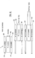
- Preferred forms of the present invention utilising a floating ram system as shown in Figure 12 provide a system whereby the actuating devices 200 and 201 are first extended, moving the device into position two as shown in Figure 12; then the second actuating device 300 is extended to its actuated position or condition, bringing the device into the position three as shown in Figure 12; the actuating devices and second actuating devices are then retracted, reverting the device into the position one as shown in Figure 12. In position one a new drill rod 7 can be added and the process described above repeated.
- Devices incorporating this preferred form of the present invention enable the length of the drill rod links 7 to be reduced in some cases for example to 2.1 metres and use a 1m drill rod.
- the weight of the device can be reduced perhaps by 30%, that is maybe down to 210 kilos giving an improved power to weight ratio.
- the drive train is believed to be more reliable than those utilising gears, cogs or cables.
- stabilisers 50,51 and 52 are advanced by means of actuators for example hydraulic actuators and bear against the internal surfaces of the hole or launch pit 4.
- the stabilisers have the effect of locking the drilling apparatus 1 into the hole 4 thus increasing the accuracy of the drilling.
- the stabilisers 50, 51 and 52 are preferably remotely controllable by an operator.
- the present invention provides a unitary directional drilling device which can be placed into a small hole 4 or above ground.
- the use of the length of drill is maximised.
Landscapes
- Engineering & Computer Science (AREA)
- Geology (AREA)
- Life Sciences & Earth Sciences (AREA)
- Mining & Mineral Resources (AREA)
- Environmental & Geological Engineering (AREA)
- Fluid Mechanics (AREA)
- Physics & Mathematics (AREA)
- General Life Sciences & Earth Sciences (AREA)
- Geochemistry & Mineralogy (AREA)
- Mechanical Engineering (AREA)
- Earth Drilling (AREA)
- Processing Of Stones Or Stones Resemblance Materials (AREA)
- Drilling Tools (AREA)
Claims (19)
- Richtungsbohrgerät (1), das zur Befestigung an einem mechanischen Arm (3) ausgebildet ist, wobei das Richtungsbohrgerät umfasst:einen Richtungsbohrkopf (20);einen verlängerbaren Bohrer (7);Mittel (30) zum Drehen des verlängerbaren Bohrers und des Bohrkopfes;Mittel (200, 201, 300) zum axialen Vorantreiben des verlängerbaren Bohrers, so dass sich der Bohrer in die Richtung des Richtungsbohrkopfes bewegt; dadurch gekennzeichnet, dass es ferner umfasst:Anbringungsmittel (57), das an einem Ende eines mechanischen Arms (3) befestigbar ist, wobei das Anbringungsmittel ein Lager (57) umfasst, das 360 Grad Drehung des Bohrgeräts (1) relativ zu dem Arm (3) um eine zu dem Bohrer (7) senkrechte Achse vorsieht; undStabilisierungsmittel (50, 51, 52), die von dem Bohrgerät (1) ausfahrbar sind und dazu ausgebildet sind, gegen das Innere einer Öffnung oder eine andere feste Oberfläche zu drücken, um das Bohrgerät zu stabilisieren.
- Richtungsbohrgerät nach Anspruch 1, worin die Stabilisierungsmittel ein Paar gegenüberliegender ausfahrbarer Platten (50, 51) an dem vorderen Ende des Bohrgeräts und eine ausfahrbare Platte (52) an dem hinteren Ende des Bohrgeräts umfassen.
- Richtungsbohrgerät nach Anspruch 1 oder Anspruch 2, worin das Anbringungsmittel ferner ein Betätigungsmittel (56) zum Steuern der Seitenneigung des Richtungsbohrgeräts umfasst.
- Richtungsbohrgerät nach einem der Ansprüche 1 bis 3, worin das Mittel zum Vorantreiben des verlängerbaren Bohrers umfasst:erste Betätigungsmittel (200, 201), die an dem Bohrgerät angebracht sind; undzweites Betätigungsmittel (300), das an den ersten Betätigungsmitteln (200, 201) angebracht ist und an dem verlängerbaren Bohrer befestigbar ist.
- Richtungsbohrgerät nach Anspruch 4, worin die ersten Betätigungsmittel und das zweite Betätigungsmittel jeweils einen hydraulischen Kolben umfassen.
- Richtungsbohrgerät nach einem der voranstehenden Ansprüche, worin das Bohrgerät weniger als 3,5 Meter lang ist.
- Richtungsbohrgerät nach Anspruch 6, worin der Bohrer (7) eine Zahl von Bohrabschnitten umfasst und jeder Bohrabschnitt weniger als 3,5 Meter lang ist.
- Richtungsbohrgerät nach Anspruch 7, worin jeder Bohrabschnitt etwa 1 Meter lang ist.
- Richtungsbohrgerät, umfassend eine Antriebsmaschine mit einem mechanischen Arm (3), der an einem seiner Enden an der Antriebsmaschine angebracht ist, und ein Bohrgerät (1), das an dem freien Ende des Arms (3) mittels eines Anbringungsmittels (57) angebracht ist, wobei das Bohrgerät (1) umfasst:einen Richtungsbohrkopf (20);einen verlängerbaren Bohrer (7);Mittel (30) zum Drehen des verlängerbaren Bohrers und des Bohrkopfs;Mittel (200, 201, 300) zum axialen Vorantreiben des verlängerbaren Bohrers, so dass sich der Bohrer in die Richtung des Richtungsbohrkopfs bewegt; dadurch gekennzeichnet, dassdas Anbringungsmittel ein Lager (57) umfasst, das 360 Grad Drehung des Bohrgeräts (1) relativ zu dem Arm (3) um eine zu dem Bohrer (7) senkrechte Achse vorsieht; unddas Bohrgerät Stabilisierungsmittel (50, 51, 52) umfasst, die von dem Bohrgerät (1) ausfahrbar sind und dazu ausgebildet sind, dass sie gegen das Innere einer Öffnung oder gegen eine andere feste Oberfläche drücken, um so das Bohrgerät zu stabilisieren.
- Richtungsbohrgerät nach Anspruch 9, worin die Stabilisierungsmittel ein Paar gegenüberstehender ausfahrbarer Platten (50, 51) an dem vorderen Ende des Bohrgeräts (1) und eine ausfahrbare Platte (52) an dem hinteren Ende des Bohrgeräts umfassen.
- Richtungsbohrgerät nach Anspruch 9 oder Anspruch 10, worin die Antriebsmaschine ein Bagger oder ein mechanischer Trockenbagger ist.
- Richtungsbohrgerät nach einem der Ansprüche 9 bis 11, worin die Antriebsmaschine dazu ausgebildet ist, dem Bohrgerät Leistung zuzuführen.
- Richtungsbohrgerät nach Anspruch 12, worin das Mittel (30) zum Drehen des verlängerbaren Bohrers und Bohrkopfs ein hydraulischer Motor ist und die Mittel (200, 201, 300) zum Vorantreiben des verlängerbaren Bohrers eine hydraulische Ramme umfassen und die von der Antriebsmaschine zugeführte Leistung hydraulische Leistung ist.
- Richtungsbohrgerät nach einem der Ansprüche 9 bis 13, worin die Mittel zum Vorantreiben des verlängerbaren Bohrers umfassen:erste Betätigungsmittel (200, 201), die an dem Bohrgerät angebracht sind; undein zweites Betätigungsmittel (300), das an den ersten Betätigungsmitteln (200, 201) angebracht ist und das an dem verlängerbaren Bohrer befestigbar ist.
- Richtungsbohrgerät nach Anspruch 14, worin die ersten Betätigungsmittel und das zweite Betätigungsmittel jeweils einen hydraulischen Kolben umfassen.
- Richtungsbohrgerät nach Anspruch 14 oder Anspruch 15, worin das zweite Betätigungsmittel Mittel umfasst, den Bohrer wahlweise zu halten.
- Richtungsbohrgerät nach einem der Ansprüche 9 bis 16, worin das Bohrgerät (1) abnehmbar an dem freien Ende des Arms (3) angebracht ist.
- Verfahren zum Richtungsbohren unter Verwendung eines Richtungsbohrgeräts nach einem der Ansprüche 9 bis 16, umfassend die Schritte:Steuern des mechanischen Arms (3), um das Richtungsbohrgerät (1) in einer Bohr-Startstellung anzuordnen und das Bohrgerät in eine Bohr-Startrichtung zu orientieren;Ausfahren von Stabilisierungsmitteln (50, 51, 52) von dem Richtungsbohrgerät; und wahlweise Drehen und Vorantreiben des Richtungsbohrkopfs, um einen Richtungsbohrvorgang auszuführen.
- Verfahren nach Anspruch 18, worin das Richtungsbohrgerät in einer Startgrube als die Bohr-Startstellung angeordnet ist und worin die Stabilisierungsmittel (50, 51, 52) ausgefahren werden, um in Wände der Startgrube einzugreifen.
Applications Claiming Priority (7)
| Application Number | Priority Date | Filing Date | Title |
|---|---|---|---|
| NZ31476997 | 1997-05-08 | ||
| NZ31476997 | 1997-05-08 | ||
| NZ31493897 | 1997-05-28 | ||
| NZ31493897 | 1997-05-28 | ||
| NZ33008098 | 1998-03-27 | ||
| NZ33008098 | 1998-03-27 | ||
| PCT/NZ1998/000055 WO1998050667A2 (en) | 1997-05-08 | 1998-05-08 | Directional drilling apparatus |
Publications (3)
| Publication Number | Publication Date |
|---|---|
| EP0980461A2 EP0980461A2 (de) | 2000-02-23 |
| EP0980461A4 EP0980461A4 (de) | 2003-01-02 |
| EP0980461B1 true EP0980461B1 (de) | 2006-08-23 |
Family
ID=27353829
Family Applications (1)
| Application Number | Title | Priority Date | Filing Date |
|---|---|---|---|
| EP98923228A Expired - Lifetime EP0980461B1 (de) | 1997-05-08 | 1998-05-08 | Richtungsbohrgerät |
Country Status (7)
| Country | Link |
|---|---|
| EP (1) | EP0980461B1 (de) |
| CN (1) | CN100360762C (de) |
| AT (1) | ATE337466T1 (de) |
| AU (1) | AU765817B2 (de) |
| DE (1) | DE69835669T2 (de) |
| ES (1) | ES2271997T3 (de) |
| WO (1) | WO1998050667A2 (de) |
Cited By (1)
| Publication number | Priority date | Publication date | Assignee | Title |
|---|---|---|---|---|
| US10982497B1 (en) | 2016-02-11 | 2021-04-20 | Roddie, Inc. | Pit launch device for horizontal directional drilling |
Families Citing this family (2)
| Publication number | Priority date | Publication date | Assignee | Title |
|---|---|---|---|---|
| CN108590508B (zh) * | 2018-03-21 | 2019-09-24 | 湖北德纳建设有限公司 | 一种用于建筑监测的钻孔设备 |
| CN111997532B (zh) * | 2020-08-11 | 2022-06-28 | 湖南长院悦诚装备有限公司 | 一种仰拱反臂钻孔结构及仰拱反臂凿岩钻机 |
Family Cites Families (13)
| Publication number | Priority date | Publication date | Assignee | Title |
|---|---|---|---|---|
| US3780816A (en) * | 1972-03-14 | 1973-12-25 | Dresser Ind | Earth boring machine with tandem thrust cylinders |
| US4553612A (en) * | 1983-11-09 | 1985-11-19 | Durham Marion E | Earth boring machine |
| US4679637A (en) * | 1985-05-14 | 1987-07-14 | Cherrington Martin D | Apparatus and method for forming an enlarged underground arcuate bore and installing a conduit therein |
| JPS62117985A (ja) * | 1985-11-16 | 1987-05-29 | 株式会社 山本鉄工所 | さく孔装置 |
| US4858700A (en) * | 1987-06-26 | 1989-08-22 | Shafer James P | Articulated apparatus for positioning rock drills |
| US5148880A (en) * | 1990-08-31 | 1992-09-22 | The Charles Machine Works, Inc. | Apparatus for drilling a horizontal controlled borehole in the earth |
| US5226488A (en) * | 1991-07-10 | 1993-07-13 | Bor-Mor Inc. | Truck mounted boring system |
| US5469155A (en) * | 1993-01-27 | 1995-11-21 | Mclaughlin Manufacturing Company, Inc. | Wireless remote boring apparatus guidance system |
| US5449046A (en) * | 1993-12-23 | 1995-09-12 | Electric Power Research Institute, Inc. | Earth boring tool with continuous rotation impulsed steering |
| US6109831A (en) * | 1995-01-10 | 2000-08-29 | Trenchless Replacement Services Ltd. | Underground boring and pipe installation |
| DE19607365C5 (de) * | 1996-02-27 | 2004-07-08 | Tracto-Technik Paul Schmidt Spezialmaschinen | Verfahren zum Lenken eines Erdbohrgeräts und ein lenkbares Gerät zum Herstellen einer Erdbohrung |
| US5709276A (en) * | 1996-03-21 | 1998-01-20 | Straightline Manufacturing, Inc. | Multi-position directional drill |
| DE19732532C2 (de) * | 1997-07-29 | 1999-10-28 | Tracto Technik | Verfahren und Vvorrichtung zum horizontalen Richtungsbohren |
-
1998
- 1998-05-08 WO PCT/NZ1998/000055 patent/WO1998050667A2/en not_active Ceased
- 1998-05-08 ES ES98923228T patent/ES2271997T3/es not_active Expired - Lifetime
- 1998-05-08 EP EP98923228A patent/EP0980461B1/de not_active Expired - Lifetime
- 1998-05-08 AU AU75566/98A patent/AU765817B2/en not_active Expired
- 1998-05-08 AT AT98923228T patent/ATE337466T1/de active
- 1998-05-08 CN CNB98806541XA patent/CN100360762C/zh not_active Expired - Lifetime
- 1998-05-08 DE DE69835669T patent/DE69835669T2/de not_active Expired - Lifetime
Cited By (1)
| Publication number | Priority date | Publication date | Assignee | Title |
|---|---|---|---|---|
| US10982497B1 (en) | 2016-02-11 | 2021-04-20 | Roddie, Inc. | Pit launch device for horizontal directional drilling |
Also Published As
| Publication number | Publication date |
|---|---|
| WO1998050667A8 (en) | 2000-02-17 |
| ES2271997T3 (es) | 2007-04-16 |
| DE69835669D1 (de) | 2006-10-05 |
| AU7556698A (en) | 1998-11-27 |
| EP0980461A4 (de) | 2003-01-02 |
| DE69835669T2 (de) | 2007-09-06 |
| CN100360762C (zh) | 2008-01-09 |
| WO1998050667A2 (en) | 1998-11-12 |
| EP0980461A2 (de) | 2000-02-23 |
| AU765817B2 (en) | 2003-10-02 |
| WO1998050667A3 (en) | 1999-11-04 |
| CN1264452A (zh) | 2000-08-23 |
| ATE337466T1 (de) | 2006-09-15 |
Similar Documents
| Publication | Publication Date | Title |
|---|---|---|
| US6497296B1 (en) | Anchoring system for a directional drilling machine and methods of use | |
| US6536539B2 (en) | Shallow depth, coiled tubing horizontal drilling system | |
| US6050350A (en) | Underground directional drilling steering tool | |
| EP0391669B1 (de) | Richtungsstangenstosser | |
| US20030070841A1 (en) | Shallow depth, coiled tubing horizontal drilling system | |
| US5580188A (en) | Method for replacing buried pipe | |
| US5070948A (en) | Directional rod pusher | |
| US11639814B2 (en) | Method of deploying a heat exchanger pipe | |
| MXPA98000447A (en) | Method for the replacement of pipe enterr | |
| US7677336B2 (en) | Portable drilling device | |
| US6799647B2 (en) | Earth drilling and boring system | |
| US5584351A (en) | Drilling machine and method of horizontal boring | |
| US6179068B1 (en) | Directional drilling apparatus | |
| EP0980461B1 (de) | Richtungsbohrgerät | |
| US5873421A (en) | Tool for installing a pipeline under a structure | |
| US20080066967A1 (en) | Apparatus and method of anchoring a horizontal directional drilling machine | |
| EP2000627A2 (de) | Richtbohrmaschine zum Bohren unterirdischer Kanäle | |
| NZ516036A (en) | Directional drilling apparatus with head being articulated relative to boom and being length adjustable | |
| US10982497B1 (en) | Pit launch device for horizontal directional drilling | |
| JPS63232905A (ja) | 穿孔装置 | |
| US20250257612A1 (en) | Directional drilling device | |
| EP2976486B1 (de) | Bohrausrüstung, insbesondere zum ausweiten eines bohrlochs in einer gesteinsformation, und verfahren zum ausweiten eines bohrlochs in einer gesteinsformation | |
| KR200318666Y1 (ko) | 굴착기용 선단조정장치 | |
| JP3019151B2 (ja) | 掘削装置およびその掘削方法 | |
| Committee on Construction Equipment and Techniques | Trenchless excavation construction methods: classification and evaluation |
Legal Events
| Date | Code | Title | Description |
|---|---|---|---|
| PUAI | Public reference made under article 153(3) epc to a published international application that has entered the european phase |
Free format text: ORIGINAL CODE: 0009012 |
|
| 17P | Request for examination filed |
Effective date: 19991125 |
|
| AK | Designated contracting states |
Kind code of ref document: A2 Designated state(s): AT BE CH CY DE DK ES FI FR GB GR IE IT LI LU MC NL PT SE |
|
| RAP1 | Party data changed (applicant data changed or rights of an application transferred) |
Owner name: FLEXIDRILL LIMITED |
|
| RIC1 | Information provided on ipc code assigned before grant |
Free format text: 7E 21B 15/04 A, 7E 21B 7/02 B, 7E 21B 7/04 B, 7E 21B 7/06 B, 7E 21B 19/086 B |
|
| A4 | Supplementary search report drawn up and despatched |
Effective date: 20021106 |
|
| AK | Designated contracting states |
Kind code of ref document: A4 Designated state(s): AT BE CH CY DE DK ES FI FR GB GR IE IT LI LU MC NL PT SE |
|
| 17Q | First examination report despatched |
Effective date: 20050124 |
|
| GRAP | Despatch of communication of intention to grant a patent |
Free format text: ORIGINAL CODE: EPIDOSNIGR1 |
|
| GRAS | Grant fee paid |
Free format text: ORIGINAL CODE: EPIDOSNIGR3 |
|
| GRAA | (expected) grant |
Free format text: ORIGINAL CODE: 0009210 |
|
| AK | Designated contracting states |
Kind code of ref document: B1 Designated state(s): AT BE CH CY DE DK ES FI FR GB GR IE IT LI LU MC NL PT SE |
|
| PG25 | Lapsed in a contracting state [announced via postgrant information from national office to epo] |
Ref country code: NL Free format text: LAPSE BECAUSE OF FAILURE TO SUBMIT A TRANSLATION OF THE DESCRIPTION OR TO PAY THE FEE WITHIN THE PRESCRIBED TIME-LIMIT Effective date: 20060823 Ref country code: IT Free format text: LAPSE BECAUSE OF FAILURE TO SUBMIT A TRANSLATION OF THE DESCRIPTION OR TO PAY THE FEE WITHIN THE PRESCRIBED TIME-LIMIT;WARNING: LAPSES OF ITALIAN PATENTS WITH EFFECTIVE DATE BEFORE 2007 MAY HAVE OCCURRED AT ANY TIME BEFORE 2007. THE CORRECT EFFECTIVE DATE MAY BE DIFFERENT FROM THE ONE RECORDED. Effective date: 20060823 Ref country code: FI Free format text: LAPSE BECAUSE OF FAILURE TO SUBMIT A TRANSLATION OF THE DESCRIPTION OR TO PAY THE FEE WITHIN THE PRESCRIBED TIME-LIMIT Effective date: 20060823 |
|
| REG | Reference to a national code |
Ref country code: GB Ref legal event code: FG4D |
|
| REG | Reference to a national code |
Ref country code: CH Ref legal event code: EP |
|
| REG | Reference to a national code |
Ref country code: IE Ref legal event code: FG4D |
|
| REG | Reference to a national code |
Ref country code: CH Ref legal event code: NV Representative=s name: E. BLUM & CO. PATENTANWAELTE |
|
| REF | Corresponds to: |
Ref document number: 69835669 Country of ref document: DE Date of ref document: 20061005 Kind code of ref document: P |
|
| PG25 | Lapsed in a contracting state [announced via postgrant information from national office to epo] |
Ref country code: DK Free format text: LAPSE BECAUSE OF FAILURE TO SUBMIT A TRANSLATION OF THE DESCRIPTION OR TO PAY THE FEE WITHIN THE PRESCRIBED TIME-LIMIT Effective date: 20061123 |
|
| REG | Reference to a national code |
Ref country code: SE Ref legal event code: TRGR |
|
| REG | Reference to a national code |
Ref country code: GR Ref legal event code: EP Ref document number: 20060403884 Country of ref document: GR |
|
| PG25 | Lapsed in a contracting state [announced via postgrant information from national office to epo] |
Ref country code: PT Free format text: LAPSE BECAUSE OF FAILURE TO SUBMIT A TRANSLATION OF THE DESCRIPTION OR TO PAY THE FEE WITHIN THE PRESCRIBED TIME-LIMIT Effective date: 20070124 |
|
| NLV1 | Nl: lapsed or annulled due to failure to fulfill the requirements of art. 29p and 29m of the patents act | ||
| ET | Fr: translation filed | ||
| REG | Reference to a national code |
Ref country code: ES Ref legal event code: FG2A Ref document number: 2271997 Country of ref document: ES Kind code of ref document: T3 |
|
| PLBE | No opposition filed within time limit |
Free format text: ORIGINAL CODE: 0009261 |
|
| STAA | Information on the status of an ep patent application or granted ep patent |
Free format text: STATUS: NO OPPOSITION FILED WITHIN TIME LIMIT |
|
| 26N | No opposition filed |
Effective date: 20070524 |
|
| REG | Reference to a national code |
Ref country code: CH Ref legal event code: PFA Owner name: FLEXIDRILL LIMITED Free format text: FLEXIDRILL LIMITED#220 LAKE ROAD#TAKAPUNA, AUCKLAND (NZ) -TRANSFER TO- FLEXIDRILL LIMITED#220 LAKE ROAD#TAKAPUNA, AUCKLAND (NZ) |
|
| PG25 | Lapsed in a contracting state [announced via postgrant information from national office to epo] |
Ref country code: MC Free format text: LAPSE BECAUSE OF NON-PAYMENT OF DUE FEES Effective date: 20070531 |
|
| PG25 | Lapsed in a contracting state [announced via postgrant information from national office to epo] |
Ref country code: LU Free format text: LAPSE BECAUSE OF NON-PAYMENT OF DUE FEES Effective date: 20070508 Ref country code: IT Free format text: LAPSE BECAUSE OF NON-PAYMENT OF DUE FEES Effective date: 20080508 Ref country code: CY Free format text: LAPSE BECAUSE OF FAILURE TO SUBMIT A TRANSLATION OF THE DESCRIPTION OR TO PAY THE FEE WITHIN THE PRESCRIBED TIME-LIMIT Effective date: 20060823 |
|
| PGRI | Patent reinstated in contracting state [announced from national office to epo] |
Ref country code: IT Effective date: 20110616 |
|
| REG | Reference to a national code |
Ref country code: FR Ref legal event code: TP Owner name: FD10G HOLDINGS LIMITED, NZ Effective date: 20110829 |
|
| REG | Reference to a national code |
Ref country code: FR Ref legal event code: PLFP Year of fee payment: 19 |
|
| REG | Reference to a national code |
Ref country code: FR Ref legal event code: PLFP Year of fee payment: 20 |
|
| PGFP | Annual fee paid to national office [announced via postgrant information from national office to epo] |
Ref country code: FR Payment date: 20170512 Year of fee payment: 20 Ref country code: IE Payment date: 20170429 Year of fee payment: 20 Ref country code: GB Payment date: 20170430 Year of fee payment: 20 Ref country code: GR Payment date: 20170529 Year of fee payment: 20 Ref country code: CH Payment date: 20170531 Year of fee payment: 20 Ref country code: DE Payment date: 20170511 Year of fee payment: 20 |
|
| PGFP | Annual fee paid to national office [announced via postgrant information from national office to epo] |
Ref country code: IT Payment date: 20170511 Year of fee payment: 20 Ref country code: ES Payment date: 20170602 Year of fee payment: 20 Ref country code: BE Payment date: 20170529 Year of fee payment: 20 Ref country code: AT Payment date: 20170526 Year of fee payment: 20 Ref country code: SE Payment date: 20170512 Year of fee payment: 20 |
|
| REG | Reference to a national code |
Ref country code: DE Ref legal event code: R071 Ref document number: 69835669 Country of ref document: DE |
|
| REG | Reference to a national code |
Ref country code: CH Ref legal event code: PL |
|
| REG | Reference to a national code |
Ref country code: GB Ref legal event code: PE20 Expiry date: 20180507 |
|
| REG | Reference to a national code |
Ref country code: AT Ref legal event code: MK07 Ref document number: 337466 Country of ref document: AT Kind code of ref document: T Effective date: 20180508 |
|
| REG | Reference to a national code |
Ref country code: IE Ref legal event code: MK9A |
|
| REG | Reference to a national code |
Ref country code: SE Ref legal event code: EUG |
|
| REG | Reference to a national code |
Ref country code: BE Ref legal event code: MK Effective date: 20180508 |
|
| PG25 | Lapsed in a contracting state [announced via postgrant information from national office to epo] |
Ref country code: IE Free format text: LAPSE BECAUSE OF EXPIRATION OF PROTECTION Effective date: 20180508 Ref country code: GB Free format text: LAPSE BECAUSE OF EXPIRATION OF PROTECTION Effective date: 20180507 |
|
| REG | Reference to a national code |
Ref country code: ES Ref legal event code: FD2A Effective date: 20200803 |
|
| PG25 | Lapsed in a contracting state [announced via postgrant information from national office to epo] |
Ref country code: ES Free format text: LAPSE BECAUSE OF EXPIRATION OF PROTECTION Effective date: 20180509 |