EP0980539B1 - Modificateur d'images a usage photographique - Google Patents
Modificateur d'images a usage photographique Download PDFInfo
- Publication number
- EP0980539B1 EP0980539B1 EP97925667A EP97925667A EP0980539B1 EP 0980539 B1 EP0980539 B1 EP 0980539B1 EP 97925667 A EP97925667 A EP 97925667A EP 97925667 A EP97925667 A EP 97925667A EP 0980539 B1 EP0980539 B1 EP 0980539B1
- Authority
- EP
- European Patent Office
- Prior art keywords
- film
- modifier
- image
- camera
- light
- Prior art date
- Legal status (The legal status is an assumption and is not a legal conclusion. Google has not performed a legal analysis and makes no representation as to the accuracy of the status listed.)
- Expired - Lifetime
Links
- 239000003607 modifier Substances 0.000 title claims description 240
- 230000003287 optical effect Effects 0.000 claims description 59
- 230000004048 modification Effects 0.000 claims description 9
- 238000012986 modification Methods 0.000 claims description 9
- 230000000694 effects Effects 0.000 description 25
- 238000009792 diffusion process Methods 0.000 description 19
- 238000000034 method Methods 0.000 description 12
- 238000010422 painting Methods 0.000 description 10
- 239000004033 plastic Substances 0.000 description 8
- 230000007246 mechanism Effects 0.000 description 7
- 230000006870 function Effects 0.000 description 4
- 230000007935 neutral effect Effects 0.000 description 4
- 238000012545 processing Methods 0.000 description 4
- 239000012530 fluid Substances 0.000 description 3
- 239000004973 liquid crystal related substance Substances 0.000 description 3
- 238000004519 manufacturing process Methods 0.000 description 3
- 239000000463 material Substances 0.000 description 3
- 230000000051 modifying effect Effects 0.000 description 3
- 238000001454 recorded image Methods 0.000 description 3
- 230000011514 reflex Effects 0.000 description 3
- 230000009471 action Effects 0.000 description 2
- 239000000853 adhesive Substances 0.000 description 2
- 230000001070 adhesive effect Effects 0.000 description 2
- 230000000903 blocking effect Effects 0.000 description 2
- 238000012937 correction Methods 0.000 description 2
- 239000011521 glass Substances 0.000 description 2
- 230000002093 peripheral effect Effects 0.000 description 2
- 230000008569 process Effects 0.000 description 2
- 230000002441 reversible effect Effects 0.000 description 2
- 206010021403 Illusion Diseases 0.000 description 1
- 230000004075 alteration Effects 0.000 description 1
- 230000008859 change Effects 0.000 description 1
- 238000004590 computer program Methods 0.000 description 1
- 230000003247 decreasing effect Effects 0.000 description 1
- 230000000994 depressogenic effect Effects 0.000 description 1
- 238000011161 development Methods 0.000 description 1
- 239000006185 dispersion Substances 0.000 description 1
- 239000000839 emulsion Substances 0.000 description 1
- 238000001914 filtration Methods 0.000 description 1
- 238000010438 heat treatment Methods 0.000 description 1
- 239000011261 inert gas Substances 0.000 description 1
- 238000001746 injection moulding Methods 0.000 description 1
- 239000007788 liquid Substances 0.000 description 1
- 230000000873 masking effect Effects 0.000 description 1
- 208000001491 myopia Diseases 0.000 description 1
- 230000004379 myopia Effects 0.000 description 1
- 238000010428 oil painting Methods 0.000 description 1
- 230000001151 other effect Effects 0.000 description 1
- 239000002985 plastic film Substances 0.000 description 1
- 229920006255 plastic film Polymers 0.000 description 1
- 229920001296 polysiloxane Polymers 0.000 description 1
- 230000002035 prolonged effect Effects 0.000 description 1
- 230000004044 response Effects 0.000 description 1
- 239000000758 substrate Substances 0.000 description 1
- 239000012780 transparent material Substances 0.000 description 1
- 230000000007 visual effect Effects 0.000 description 1
- 238000010429 water colour painting Methods 0.000 description 1
- 238000004804 winding Methods 0.000 description 1
Images












Classifications
-
- G—PHYSICS
- G03—PHOTOGRAPHY; CINEMATOGRAPHY; ANALOGOUS TECHNIQUES USING WAVES OTHER THAN OPTICAL WAVES; ELECTROGRAPHY; HOLOGRAPHY
- G03B—APPARATUS OR ARRANGEMENTS FOR TAKING PHOTOGRAPHS OR FOR PROJECTING OR VIEWING THEM; APPARATUS OR ARRANGEMENTS EMPLOYING ANALOGOUS TECHNIQUES USING WAVES OTHER THAN OPTICAL WAVES; ACCESSORIES THEREFOR
- G03B11/00—Filters or other obturators specially adapted for photographic purposes
-
- G—PHYSICS
- G03—PHOTOGRAPHY; CINEMATOGRAPHY; ANALOGOUS TECHNIQUES USING WAVES OTHER THAN OPTICAL WAVES; ELECTROGRAPHY; HOLOGRAPHY
- G03B—APPARATUS OR ARRANGEMENTS FOR TAKING PHOTOGRAPHS OR FOR PROJECTING OR VIEWING THEM; APPARATUS OR ARRANGEMENTS EMPLOYING ANALOGOUS TECHNIQUES USING WAVES OTHER THAN OPTICAL WAVES; ACCESSORIES THEREFOR
- G03B17/00—Details of cameras or camera bodies; Accessories therefor
- G03B17/02—Bodies
- G03B17/12—Bodies with means for supporting objectives, supplementary lenses, filters, masks, or turrets
-
- G—PHYSICS
- G03—PHOTOGRAPHY; CINEMATOGRAPHY; ANALOGOUS TECHNIQUES USING WAVES OTHER THAN OPTICAL WAVES; ELECTROGRAPHY; HOLOGRAPHY
- G03B—APPARATUS OR ARRANGEMENTS FOR TAKING PHOTOGRAPHS OR FOR PROJECTING OR VIEWING THEM; APPARATUS OR ARRANGEMENTS EMPLOYING ANALOGOUS TECHNIQUES USING WAVES OTHER THAN OPTICAL WAVES; ACCESSORIES THEREFOR
- G03B17/00—Details of cameras or camera bodies; Accessories therefor
- G03B17/24—Details of cameras or camera bodies; Accessories therefor with means for separately producing marks on the film, e.g. title, time of exposure
-
- G—PHYSICS
- G03—PHOTOGRAPHY; CINEMATOGRAPHY; ANALOGOUS TECHNIQUES USING WAVES OTHER THAN OPTICAL WAVES; ELECTROGRAPHY; HOLOGRAPHY
- G03B—APPARATUS OR ARRANGEMENTS FOR TAKING PHOTOGRAPHS OR FOR PROJECTING OR VIEWING THEM; APPARATUS OR ARRANGEMENTS EMPLOYING ANALOGOUS TECHNIQUES USING WAVES OTHER THAN OPTICAL WAVES; ACCESSORIES THEREFOR
- G03B2217/00—Details of cameras or camera bodies; Accessories therefor
- G03B2217/24—Details of cameras or camera bodies; Accessories therefor with means for separately producing marks on the film
- G03B2217/248—Details of cameras or camera bodies; Accessories therefor with means for separately producing marks on the film with means for masking
-
- G—PHYSICS
- G03—PHOTOGRAPHY; CINEMATOGRAPHY; ANALOGOUS TECHNIQUES USING WAVES OTHER THAN OPTICAL WAVES; ELECTROGRAPHY; HOLOGRAPHY
- G03B—APPARATUS OR ARRANGEMENTS FOR TAKING PHOTOGRAPHS OR FOR PROJECTING OR VIEWING THEM; APPARATUS OR ARRANGEMENTS EMPLOYING ANALOGOUS TECHNIQUES USING WAVES OTHER THAN OPTICAL WAVES; ACCESSORIES THEREFOR
- G03B2217/00—Details of cameras or camera bodies; Accessories therefor
- G03B2217/26—Holders for containing light-sensitive material and adapted to be inserted within the camera
-
- G—PHYSICS
- G03—PHOTOGRAPHY; CINEMATOGRAPHY; ANALOGOUS TECHNIQUES USING WAVES OTHER THAN OPTICAL WAVES; ELECTROGRAPHY; HOLOGRAPHY
- G03B—APPARATUS OR ARRANGEMENTS FOR TAKING PHOTOGRAPHS OR FOR PROJECTING OR VIEWING THEM; APPARATUS OR ARRANGEMENTS EMPLOYING ANALOGOUS TECHNIQUES USING WAVES OTHER THAN OPTICAL WAVES; ACCESSORIES THEREFOR
- G03B2219/00—Cameras
- G03B2219/02—Still-picture cameras
- G03B2219/04—Roll-film cameras
- G03B2219/045—Roll-film cameras adapted for unloading the film in the processing laboratory, e.g. disposable, reusable or recyclable cameras
Definitions
- This invention relates generally to photographic image modifying equipment, and more particularly, to photographic image modifiers for introducing to a photographic negative during its exposure image a special effect such as an effect which is indicative of a painting.
- U.S. Patent No. 3,916,423, issued to Ueda et al. discloses a device for transposing information (characters, lines or designs) onto the surface of film during exposure of the film to an image.
- a transparent plate having an opaque mask is attached to a film cartridge in front of and adjacent to a frame of film.
- the opaque mask located on the transparent plate prior to the light reaching and exposing the film.
- the result is under-exposed regions of the film (negative) corresponding to the particular shape of the opaque mask.
- the negative is used to expose a positive print
- the shape of the particular opaque mask will be positively transposed in the form of dark overexposed regions in the final print.
- a conventional camera usually includes at least one integral light meter which is used to measure the average intensity of light entering the camera prior to exposing the film.
- the light meter generates an electrical signal that is interpreted by a computer and is used to control either the size of the aperture of the lens, the speed of the shutter, or both, so that the average intensity of light is compensated throughout the entire picture, as recorded by the film.
- N-90, N90s, and F5 manufactured by Nikon several separate light meters are used, each measuring the intensity of light within a particular zone or region of the frame (an upper region is used to measure the intensity of light from the sky of the scene, for example.
- an upper region is used to measure the intensity of light from the sky of the scene, for example.
- the camera cannot control the amount of light from a particular region of the framed scene reaching the corresponding region of the film without effecting the amount of light reaching the other regions of the film.
- the overall density of the negative can be corrected by adjusting either the aperture of the lens or the operating speed of the shutter, however, this exposure correction has a uniform effect over the entire recording area of the film (i.e., the frame). If the aperture is decreased to lessen the amount of light reaching the film to compensate for the "bright" spots of the subject or scene, for example, the otherwise “neutral” or normal areas of the subject or scene will now become too dark. If the speed of the shutter is prolonged to "burn in” the darker regions of the image, the normal areas will become unacceptably overexposed and "washed out".
- bracketing technique of photography there are several problems with the bracketing technique of photography. Not only is a lot of film exposed for few different images, only relatively expensive cameras offer exposure control, let alone automatic bracketing of the exposure. Also, although exposure bracketing provides several pictures to select from, since the camera's exposure meter must account for the total received light and may locally connect the exposure of a portion of the image frame, all of the bracketed pictures will show varying degrees of over and under-exposure. In other words, if there is an overexposed region of an image, bracketing will not correct the exposure of that particular region, merely hide it by changing the total exposure throughout the image, as recorded by film.
- Special segmented, or zone filters include regions of varying opacity which may be aligned within a particular scene to compensate for highlighted regions, such as a cloudy sky. These filters rarely align with the image detail and are only useful when the specific regions defined by the filter align with the regions of the scene.
- any underexposed or overexposed regions may be compensated during the production of a photographic print using well known techniques known as "dodging” or “burning” in which a density mask (made from opaque and semi-transparent sheet material) is held in the exposure path (over the photographic paper) when a print is being made from a negative.
- the mask is used to selectively protect overexposed areas of the negative from a portion of the light projected to the photographic paper during image enlargement (or print processing).
- these techniques are used in expensive custom print processing, not in cheaper automated print processing.
- a first example not part of the invention comprises a transparent plate mounted at the film plane within a camera.
- the transparent plate has a translucent diffusion pattern which diffuses incoming light rays reflected from the subject and effectively repositions them in a controlled manner prior to their exposure on film.
- Proposed diffusion patterns may alter the light rays to create characteristics indicative of various types of paintings.
- the transparent plate having the translucent diffusion pattern is mounted in a film cartridge.
- a length of plastic film (a pattern strip) is positioned adjacent to a similar length of photographic film (film strip).
- An appropriate translucent diffusion pattern is provided onto one surface of the pattern strip, along its entire length. Both strips are rolled into a conventional 35 mm film canister and dispensed simultaneously, as needed (within the camera) so that each frame of film has a separate mask in front of it, at the film gate of the camera.
- a transparent plate having a translucent diffusion pattern is positioned between the main lens of the camera, and the camera body.
- a correcting lens is required to bring the pattern of the particular pattern into sharp focus with the image at the film plane to be exposed on film.
- an LCD is mounted in front of the film of a camera and is used to compensate for specific regions of an image before the image light exposes the film.
- a number of transparent members, each having a different translucent diffusion pattern is slidably displacable between a stowed position which is remote from the film gate of the camera, and a film gate position wherein one or more transparent members are positioned within the film gate, between the film and the camera's lens.
- a disposable SLR-type camera incudes a pivotal mirror located between the camera's lens and eyepiece that may be rotated to a first position wherein incoming light from an image is directed to the eyepiece, and a second position wherein the incoming light is directed to film.
- the rotatable mirror may function as a light modifier and may be easily replaced with other modifiers.
- a camera 10 (an SLR) is shown having a camera body 12, a lens assembly 14 attached to a front side of the camera body 12, and a frame of film 16 shown in cross section at a film gate 18 (see also, Fig 2c ).
- the specific structures of both the film gate 18 and the shutter mechanism 19 of the camera 10 are conventional and are therefore not shown in full detail.
- the shutter mechanism 19 is located in front of (i.e., closer to) the lens 14, the modifier 20 and, of course, the frame of film 16.
- the modifier 20, described in greater detail below, is sized and shaped to fit within the film gate 18 between the film 16 and the shutter of the camera 10.
- a conventional, spring-loaded, film pusher plate 21 which is usually mounted to the inside surface of the door (not shown) of the camera (used to access the film) lightly pushes the film flat across the film gate 18, and adjacent a rear surface of the modifier 20.
- the modifier 20, in accordance with one example not part of the invention includes a transparent plate 22 and a diffusion pattern 24.
- the transparent plate 22 is preferably shaped to include a raised (or thicker) center section 26 which defines two (thinner) edge sections 28.
- the edge sections 28 are designed to contact portions of the camera positioned adjacent to the film gate 18 to hold the entire modifier 20 in the camera with the center section positioned within the film gate 18 of the camera 10, as shown in cross-section in Fig. 2c .
- the diffusion pattern 24 functions as a translucent mask by diffusing and distorting the incident light prior to it reaching and exposing the film.
- the diffusion pattern 24 preferably does not prevent the light from reaching the film (i.e., the pattern is not opaque).
- the transparent plate 22 of the modifier 20 is preferably made from an optical-grade plastic, however, optical grade glass may also be used.
- the diffusion pattern 24 is preferably formed on a rear surface 30 (facing the film 16 when installed in the camera 10) of the transparent plate 22.
- a preferred method of forming the diffusion pattern 24 is to emboss the particular pattern (or its negative or reverse) into the rear surface of the plastic transparent plate 22.
- a reverse pattern is first machined into a stamping surface of a hard material.
- the plastic transparent plate 22 is then softened (by using flameless heat, such as steam or electric filament or through the use of other indirect heating) and pressed against the stamping surface so that the pattern is transformed into the rear surface of the plastic plate 22, thereby creating the diffusion pattern 24.
- flameless heat such as steam or electric filament or through the use of other indirect heating
- the diffusion pattern 24 effectively distorts the incoming light, and therefore also the image, in a controlled manner.
- the distortion of the image follows the particular diffusion pattern 24 which is discernable, because the transparent plate 22 and the pattern 24 are both located at the film plane (also called the focal plane) and are in soft focus (not sharp).
- the pattern 24 appears somewhat softened (not in sharp focus) because although the pattern 24 is effectively at the point of focus, the pattern 24 is not a mask (not opaque), but a light diffuser which disperses the incident light by a small amount just before it reaches and exposes the film. This controlled dispersion of the light aids in achieving the desired special effect to the exposed image, as discussed below.
- the modifier 20 be located as close to the surface of the film as physically possible. If the modifier 20 is the type which is stationary with respect to the camera, as shown in Figs. 2a-2c and discussed above, it is preferable that the modifier not make contact with the film, to avoid unwanted scratches as the film is advanced.
- an optical modifier 32 is incorporated into the structure of an otherwise convention film cassette 34 (typically referred to as film-type 120).
- the cassette 34 includes a film supply section 36, a film pick-up section 38; and a connecting portion 40 connecting the film supply section 36 with the film pick-up section 38.
- the connecting portion 40 includes an integral film gate 42 which aligns with the film gate of the camera (not shown) which is adapted to receive the cassette 34.
- the modifier 32 in this example, is preferably positioned (during manufacture of the cassette 34) within the structure which makes up the connecting portion 40 so that it lies across the film gate 42 and adjacent the film 16.
- the modifier 32 as in the above-described embodiment of Figs. 1 and 2a-2c , includes a specific diffusion pattern 24.
- the position of the modifier 32 forces all light passing through the film gate 42 to also pass through the modifier and become slightly diffused prior to the light reaching and exposing the film 16.
- the modifier 50 takes the form of a thin translucent plastic strip (similar to the substrate material used in photographic film).
- the strip modifier 50 is affixed to the inside surface 52 (emulsion side) of an otherwise conventional roll of film 16 (type 35 mm). Both the film 16 and the affixed strip modifier 50 are rolled up together into the standard film canister (not shown) using the standard spool 54. It is preferred that the strip modifier 50 be attached only at selected points 56 such as the ends of the strip modifier 50 or perhaps between each frame (not shown) using a heat bond or an appropriate adhesive.
- film 16 is shown as a 35 mm format, film 16 may be of any film format, including 120, 220, 4x5, 110, and POLAROIDTM-type film/paper.
- modifier 50 is attached to or is positioned across from each sheet of film/paper and is removed after exposure and development of the particular image.
- Fig. 6 illustrates (in cross-section) a conventional SLR camera 10 (similar to the camera 10 shown in Fig. 1 ), having the film 16 of Fig. 5 installed.
- the strip modifier 50 is shown positioned in front of the film 16 (closer to the lens 14) and across the film gate 18.
- Figs. 7 and 8 illustrate an optical modifier 60 in accordance with another example not part of the invention which is similar to the modifier shown in Figs. 2a-2c and discussed above.
- the modifier 60 is the same size of the film gate 18, i.e., the modifier 60 does not include the edge sections 28.
- the modifier 60 is positioned permanently within the film gate 18 using an appropriate adhesive, for example.
- the modifier 60 may also snap into place within the film gate 18 using a close tolerance fit or appropriate ridges and/or detents.
- the modifier 60 shown in this example is especially useful for disposable type cameras.
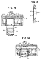
- FIG. 9 through 12 yet another optical modifier 70 is shown.
- the modifier 70 is mounted into the frame structure of a cartridge 72.
- the cartridge 72 is a thin plate which is adapted to be inserted into a slot 74 located in a camera 76.
- the camera 76 is either specially made with the slot 74 or a replaceable camera back (not shown) may be provided having a slot 74.
- the slot 74 positions the cartridge 72 so that the modifier 70 (mounted within the cartridge 72) aligns into a position between the film gate 18 and the film 16, as shown in Figs. 11 and 12 .
- One of a variety of cartridges 72 (each having a different modifier 70) may be inserted into the slot 74.
- Each cartridge 72 preferably includes a handle which remains accessible when the cartridge 72 is inserted into the slot 74.
- the slot 74 and/or the insertable cartridge 72 includes an appropriate light-barrier to prevent unwanted light from entering the camera through the slot opening and exposing the film.
- a modifier coupler 80 is positioned between the camera body 12 and the lens assembly 14.
- the modifier coupler 80 couples the lens assembly 14 to the camera body 12 and passes the incoming light from the lens assembly 14 to the film gate 18 of the camera 10.
- the modifier coupler 80 includes an image plane 82, a primary lens assembly 84, a secondary lens assembly 86, a modifier receiving slot 88, and a filter receiving slot 90.
- each of several different modifiers 20 is mounted to a plate 92.
- Several selected plates 92 are mounted to a plate holder 94, as shown in Fig. 14 .
- the plate holder 94 is adapted to be mounted to the modifier coupler 80, adjacent the modifier receiving slot 88.
- the plate holder 94 is mounted so that it may slide relative the modifier coupler 80 in such a manner that allows any selected one of the several plates 92 held in the plate holder 94 to align with the modifier receiving slot 88.
- the selected plate 92 once aligned with the modifier receiving slot 88, may be moved into the modifier coupler 80 so that the selected modifier 20 aligns with the path of incoming light from the lens assembly 14.
- a selected plate 92 is shown in an inserted position in Figs. 14 and 15 .
- Other light modifiers such as conventional filters may be inserted into the filter receiving slot 90.
- the internal lenses of the lens assembly 14 and the primary lens assembly 84 will focus the reflected light of a subject onto the image plane 82 of the coupler 80 (the image will be inverted).
- the inverted image is modified by the selected modifier 20 located at the image plane 82.
- the secondary lens assembly 86 re-focuses the image (and uprights the image) onto the film plane which is located at the film gate 18 of the camera 10.
- the modifier 20 is located as close as possible to the focal plane of the camera 10 regardless of the location of the focal plane with respect to the film plane.
- a single focal plane is usually located at the film plane, it is possible to create two effective focal planes, one located a prescribed distance from the film plane towards the subject, the other located at the film plane 18.
- a camera 100 having an optical modifier assembly 102 is shown, in accordance with another embodiment of the invention.
- the camera 100 in this particular embodiment is intended to be a disposable type made using relatively inexpensive parts and including a built-in supply of film.
- the camera 100 in this embodiment may likewise be a non-disposable type.
- the camera 100 includes a camera body 104 having a front face 106 and a lens aperture 108.
- the commercially available conventional disposable camera i.e., one not including the modifier assembly of this invention
- the conventional lens (not shown) focuses a subject located in front of the camera, onto a frame of film located at the film plane (located in the rear of the camera).
- the optical modifier assembly 102 includes a first outer lens 110 located farthest from the film plane, and a second inner lens 112 located adjacent the front face 106 of the camera 100.
- An optical modifier 114 is located and movable within a plane lying between the inner and outer lenses (112, 110) and parallel to the film plane of the camera 100.
- the outer lens 110 focuses the light reflected off a subject located in front of the camera onto an intermediate focal plane 115.
- the inner lens 112 focuses the image located at the intermediate focal plane 115 onto the film plane. It is desirable to position the optical modifier 114 close to the intermediate focal plane so that the distortion applied to the light from the subject may be recorded on film in sharp focus (that is, as focused as the diffusion of the passing light through the modifier will allow).
- the optical modifier 114 is mounted to an arm 116.
- the arm 116 is pivotally connected to a housing 118 of the optical modifier assembly 102.
- a portion of the arm 116 is accessible to the user of the camera 100 and may be displaced, moving the optical modifier 114 between a stowed position (shown in Fig. 17 in dashed lines) wherein the incoming light passes directly to the film and is not otherwise distorted (except by the lenses), and an interference position wherein the optical modifier 114 is located in the path of the light (shown in Fig. 17 , in solid lines).
- a preferred embodiment of the invention as applied to disposable cameras, is shown, wherein the optical modifier 114 is mounted along the edge of a disc 120.
- the disc 120 is pivotally attached to the body of the camera 100 at a central pivot point 122.
- the disc 120 includes several peripheral openings 124 which include one of several different optical modifiers 114 for achieving different effects.
- the disc 120 is mounted so that any one of the openings 124 may be positioned in front of the lens aperture 108.
- the operator of the camera 100 may select a particular effect by rotating the disc 120 until the appropriate optical modifier 114 aligns with the lens aperture 108.
- a lever 126 may be provided for assisting in the rotation of the disc 120.
- an indicator (not shown) may be included to point to indicia located on the face of the camera body, for example, indicating the particular effects in use.
- FIG. 21-22 another embodiment of the invention is shown wherein the optical modifier 114 is mounted onto an elongated panel 128.
- the panel 128 include two parallel internal edges 130 which define an elongated window.
- Several sliding plates 132 are slidably positioned between the two edges 130.
- the panel 128 is mounted to the front face of the camera 100 so that each plate 132 may be selectively moved between a stowed position and a usable position, located in front of the lens aperture 108.
- Each plate 132 includes an opening 134 across which lies one of several different optical modifiers 114.
- Each plate 132 preferably includes an accessible handle 136 which may be grasped by the camera operator to move the plates 132 with respect to the lens aperture 108, as necessary.
- a representation of a non-modified photograph is shown in Fig. 23 .
- One purpose of the invention is to modify the image of a subject (i.e., the light reflected from the subject entering the camera) to introduce visual characteristics indicative of a painting.
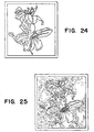
- One particular optical modifier 114 modifies the image to introduce an impressionistic appearance, as shown in Fig. 24 .
- Fig. 24 Here, all the detail is distorted, yet the image remains substantially in focus.
- Another optical modifier 114 introduces a "craquelure" effect (typical of old oil-base paintings) to the original flower image so that the resulting print resembles Fig. 25 .
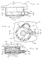
- Figs. 26-28 Another embodiment, similar to the one shown in Figs. 19 and 20 and described above, is shown in Figs. 26-28 and includes a modifier housing 200, a modifier turret 202, and a primary-lens housing 204.
- the modifier housing 200 is preferably formed integrally with a face of a disposable-type camera 206, yet could also be formed separately and adapted to attach to a face of any camera 206 to be used as a camera attachment.
- the modifier housing 200 includes a front wall 208 and an aperture 210 which is aligned with the primary-lens aperture 212 of the camera 206.
- a secondary-lens tube 214 is located behind the front wall 208 and preferably includes an appropriate lens (not shown) which is designed to re-focus an image located at an intermediate focal plane 216 onto the film.
- the intermediate focal plane 216 is preferably located just in front of the front wall 208, at the location of the modifier turret 202.
- the modifier turret 202 is pivotally connected to a portion of the modifier housing 200 at a pivot pin 218.
- the modifier turret 202 is rotatable about the pivot pin 218.
- the primary-lens housing 204 is preferably fixed relative to the camera 206 and the modifier housing 200 by the pivot pin 218 or by being formed integrally with (or otherwise connected to) the camera 206.
- the primary-lens housing 204 supports a primary lens 220.
- the primary lens 220 is designed to focus the incoming light reflected from an image in front of the camera to the intermediate focal plane 216.
- the primary lens 220 may be mounted in a primary-lens tube 222.
- the modifier turret 202 includes at least two openings 224, as shown in Fig. 28 .
- One opening 224 may include an optical modifier 226, for example.
- the other opening (or openings) shown in Fig. 28 may be left open, include a clear element 227 or a translucent element having a frosted surface or include another optical modifier element.
- Other variations of the modifier turret are possible including several different modifiers such as one for producing "craquelure", impressionism, or other painting-related effects.
- the modifier turret 202 preferably further includes indicia 228 or other indication of the type of modifier (or lack thereof) in use.
- the primary-lens housing 204 may further include an indicator opening 230 which aligns with the indicia printed on the modifier turret 202 so that an operator may view the indicia 228 to learn which modifier, if any, is located in the path of incoming light and will effect the film.
- the turret 202 further includes a rubber O-ring 232 along its periphery to ensure high friction for positive gripping while being rotated by an operator.
- the O-ring is shown in Fig. 27 .
- Other gripping peripheral surfaces include a roughened edge (not shown) and serrations 234 shown in Fig. 28 , in place of the rubber O-ring 232 of Fig. 27 .
- the operator rotates the modifier turret 202 while viewing indicia 228 through the indicator opening 230 until a desired modifier effect is indicated.
- the modifier will be in position in front of the primary lens 220 and will effect the film accordingly.
- a camera 300 includes a body 302, a lens assembly 304, an eyepiece 306, a film gate 308, a first pivotally mounted modifier 310 pivotal about a first pivot point 311 and a second pivotally mounted modifier 312 pivotal about a second pivot point 313.
- a first pivotally mounted modifier 310 pivotal about a first pivot point 311
- a second pivotally mounted modifier 312 pivotal about a second pivot point 313.
- first pivotally mounted modifier 310, 312 are shown in this example.
- four or more modifiers may be implemented with this example.
- Each modifier is pivotal between a stowed position wherein incoming light entering camera 300 through lens assembly 304 is not interrupted, allowing, the light to reach film (not shown) located within film gate 308, when the shutter (not shown) is open.
- Fig. 29a shows both modifiers 310, 312 in the stowed position, in which case, camera 300 will function similar to a conventional camera in that unmodified pictures will be recorded on film.
- Fig. 29b shows second modifier 312 located within or just adjacent to film gate 308 (and also in front of the shutter and the film), while first modifier 310 remains in the stowed position.
- Fig. 29c shows first modifier 310 located within or just adjacent to film gate 308 (and also in front of the shutter and the film), while second modifier 312 is relocated back to stowed position.
- Each modifier 310, 312 is preferably spring biased to its stowed position, as shown in Fig. 29a , and must be mechanically pivoted to its film gate position, shown in Figs. 29b and 29c . Any appropriate mechanism may be used to pivot either or both modifiers between their stowed and film gate positions, as would be known to those skilled in the art.
- camera 300 selects a subject for recording on film and then selects if the image should be modified, for example to appear like a painting, and which type of modifier (already installed in camera 300) should be used. If no modifier is to be used, camera 300 may operate in a conventional manner, however, if it is desired to deploy a modifier 310, 312, from its stowed position to the film gate position, an appropriate actuator located on camera 300 may be activated to mechanically or electro-mechanically pivot either (or both) modifier(s) 310, 312 from its stowed position, against the action of the spring bias, to the film gate position. Appropriate electronics and software may be used to automatically return each deployed modifier back to its stowed position after each picture is taken.
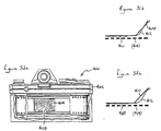
- a camera 400 includes a body 402, a film gate 404, film 406, a first modifier 408, a second modifier 410, rails 412, and a shutter 414.
- each modifier 408, 410 is slidably mounted to rails 412 that are positioned on opposing sides of film gate 404 and extend to a location within body 402 that is remote from film gate 404.
- either modifier 408, 410 (or both) may be slidably displaced along rails 412 between a stowed position shown in Fig. 30b , and a film gate position shown in Figs. 31b and 32b .
- the modifiers. 408, 410 may be moved along rails 412 using any appropriate mechanism. Such a mechanism may be driven using an internal electric motor that is controlled by an on-board processor (not shown) or manually by lever action directed manipulated by the user of camera 400.
- Figs. 30a and 30b show both modifiers 408, 410 located in the stowed position so that neither modifier will alter the image light entering camera 400 before reaching film 406.
- Figs. 31a and 31b show first modifier 408 located in the film gate position, while second modifier 410 remains in the stowed position so that first modifier 408 will modify the incoming light prior to it reaching film 406.
- Figs. 32a and 32b show second modifier 410 located in the film gate position, while first modifier 408 is located in the stowed position so that only second modifier 410 will effect the image light prior to it reaching film 406.
- first modifier 408 may modify the image light to include impressionistic characteristics and second modifier 208 may modify the image light to include craqueleur characteristics, so that the operator of camera 400 may select either of these modifications, or neither (a normal picture) or both modifiers creating a third different modification.
- This example may include any number of modifiers 408, 410. Only two modifiers are shown and described for clarity.
- incoming light from an image passes through a lens assembly and is reflected to an eyepiece using a pivotal mirror and a prism (or a second, stationary mirror), so that the camera operator may view the exact image as seen through the lens.
- the lens typically includes means for focusing the image and an aperture for controlling the amount of light that enters the camera.
- a schematic of a single-use single lens reflex (SLR) camera 500 is shown, according to another example not part of the invention, including a lens assembly 502, a fixed mirror 504, a pivotal mirror 506, a viewing screen 508, an eyepiece 510, a film cassette 512, and a film gate 514.
- Film cassette 512 and film gate 514 are-preferably located in the front of camera 500, above lens assembly 502, as shown in Figs. 33a-33b , opposite viewing screen 508 and eyepiece 510.
- the purpose of this example of the invention is to provide a camera that combines the benefits of an SLR camera with the simplicity and low cost of a single-use camera.
- Lens assembly 502 preferably includes a built-in, single-speed shutter similar to the type of lens/shutters used in conventional single-use cameras.
- Pivotal mirror 506 is pivotally mounted within camera 500 and may be angularly displaced between a viewing position (shown in Fig. 33a ) and an exposing position .
- image light from the subject enters camera 500 through lens assembly 502 (and shutter, not shown), is projected onto viewing screen 508 by way of fixed mirror 504, and pivotal mirror 506.
- the image projected onto viewing screen 508 may be viewed through eyepiece 510 in a conventional manner. Film is not exposed to the image light when pivotal mirror 506 is in the viewing position.
- pivotal mirror 506 When pivotal mirror 506 is in the exposing position, the same image light passing lens assembly 502 and the shutter (not shown) reflects off of fixed mirror 504 and pivotal mirror 506 to film gate 514 and film 512. Image light may not be viewed when pivotal mirror 506 is in the exposing position.
- the shutter located within lens assembly 502 may open only when pivotal mirror 506 is located either in the viewing position ( Fig. 33a ) or the exposing position, not when pivotal mirror 506 is moving between the two positions, as shown in Fig. 33b .
- the shutter of the camera is biased open and pivotal mirror 506 is in the viewing position so that the operator may see the image of the subject through the lens (similar to a conventional, more expensive, single lens reflex camera).
- a button (not shown) is released which closes the shutter thereby blocking image light from entering camera 500, and simultaneously rotates pivotal mirror 506 from the viewing position to the exposing position.
- pivotal mirror 506 reaches the exposing position, the shutter automatically opens and re-closes (preferably at a set shutter speed) to expose the image onto the frame of film that is located within film gate 514.
- pivotal mirror 506 is returned to the viewing position and, again the shutter re-opens to reveal the image light to the operator so that the next picture may be viewed.
- Lens assembly 502 focuses the image light either onto viewing screen 508 or the film located within film gate. Therefore, the distance the image light must travel from fixed mirror 504, past pivotal mirror 506, to viewing screen 508 is the same as the distance from the fixed mirror 504, past pivotal mirror 506, to film gate 514.
- Pivotal mirror 506 may be rotated using a motor (not shown) or using a pre-wound main spring that has sufficiently rotational energy to operate the pivotal mirror 506 and expose all the film of film cassette 512. Any suitable mechanism may be used to operate the shutter in concert with pivotal mirror 506, as would be known by those skilled in the art.
- pivotal mirror 506 may include a light modifier, as described earlier in this application, so that the image light is modified, distorted, or otherwise altered prior to being recorded on film.
- Pivotal mirror 506 may include two or more functional sides, wherein several different types of modifiers may be incorporated and selected.
- a schematic of a single-lens-reflex (SLR) camera 600 including a body 602, a lens assembly 604, an aperture 606, a pivotal mirror and prism assembly 608, an eyepiece 610, a shutter 612 and film 614.
- SLR single-lens-reflex
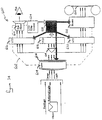
- camera 600 includes a multi-segmented light meter 616, a reference liquid crystal display neutral-density filter (LCD-ND) filter 620, and a compensating LCD-ND filter 622
- pivotal mirror/prism assembly 608 effectively divides the light rays entering camera 600 through lens 604 (as "image light") into three separate paths, each path receiving all of the image light; a first path is directed to eyepiece 610, through reference LCD-ND filter 620, a second path is directed to multi-segmented light meter 616, and a third path is directed to film 614, through compensating LCD-ND filter 622 and shutter 612.
- Multi-segment light meter 616 converts (digitizes) the optical image light it receives into electronic signals similar to the manner in which a charged coupled device (CCD) converts optical information to electrical signals to record an optical image onto video tape.
- Multi-segment light meter 616 is preferably a CCD type sensor.
- the information is read by a processor 618.
- the received information includes the intensity (brightness) of each pixel of the image light, as measured by multi-segment light meter 616.
- processor 618 uses the information from multi-segment light meter 616 to categorize pixels of multi-segment light meter 616 that have similar contrast levels (or exceed a predetermined intensity level) thereby identifying the group of pixels that represent a foreground object (or objects) against pixels that represent a background image (or images).
- LCD-ND filter liquid crystal display neutral density filter
- compensating liquid crystal display neutral density filter 622 LCD-ND filters 620 and 622 are preferably high resolution clear-plate LCDs and function as light valves (for each pixel).
- Reference LCD-ND filter 620 is physically positioned in front of eyepiece 610, as described below.
- Compensating LCD-ND filter 622 is physically positioned in front of shutter 612, as described below.
- Processor 618 may selectively control the collective density of each pixel in a selected group so that an entire group of pixels representing a foreground subject, for example, may be made effectively opaque, or uniformly semi-opaque, thereby forming a "mask” that may be used to block specific regions of the image light (corresponding to the "bright” regions of the image) from reaching film 614 (for at least a portion of the exposure time).
- a controller 624 is electrically connected to processor 618 and is used to control the density of either a foreground subject, or a background image. This is done simply by controlling the feed voltage to LCD-ND filters 620, 622. Varying the voltage to LCD-ND filters 620, 622, will vary the opacity of each selected pixel of LCD-ND 620, 622.
- Processor 618 uses the digitized image data to select the pixels of both LCD-ND filters 620, 622.
- Reference LCD-ND filter 620 is positioned in front of eyepiece 610 so that the image light directed to eyepiece 610 by pivotal mirror/prism assembly 608 must pass through reference LCD-ND filter 620.
- Selected pixels of LCD-ND filter 620 will cause the image light directed to eyepiece 610 to be selectively masked, according to the digitized image data sent to processor 618.
- the operator may view the image through eyepiece 610 with a superimposed mask of darkened (selected) pixels of reference LCD-ND filter 620 covering the selected "bright" areas of the image.
- processor 618 controls compensating LCD-ND filter 622 in a similar manner so that the image light that is simultaneously directed, by pivotal mirror/prism assembly 608, to shutter 612 must pass through LCD-ND filter 622.
- processor 618 selectively darkens selected regions of compensating LCD-ND filter 622 so that selected regions of film 614 is protected, for a predetermined period of time during exposure of film 614 (when shutter 612 opens).
- Processor 618 further controls the operation of shutter 612 and aperture 606 so that processor 618 may control the proper exposure time for the non-masked regions of the image light, in further response to the specific aperture and shutter speed settings controlled by the operator, as understood by those skilled in the art.
- Processor may further control and change the relative opacity of any pixel or groups of pixels during the exposure. This includes shifting darkened pixels or pixel groups in rapid succession during the exposure period (shutter open) across the entire "bright" region of the image or simply along a boundary-line of two regions of varying contrast (bright sky next to foreground person). This controlled shifting during the exposure mimics the dodging process used in conventional print processing. By moving the mask, the masking effects may be softened to provide a more realistic exposure correction.
- camera 600 is shown recording an image onto film 614.
- the image shown here includes a woman located in the foreground wearing a black hat against a bright partly-cloudy sky.
- the image enters camera 600 as described above (see Fig. 34 ), it is simultaneously sent to multi-segmented light meter 616, reference LCD-ND filter 620, and LCD-ND filter 622.
- Multi-segmented light meter 616 digitizes the image light it receives and sends pixel-intensity information to processor 618 which in turn categorizes the image into groups of pixels having densities exceeding preset levels.
- the pixels representing the woman and her hat are considered dark compared to the bright background sky and are therefore grouped together and electronically displayed on both reference LCD-ND filter 620 and compensating LCD-ND filter 622 as transparent, as shown in Fig. 35 .
- the bright sky portion of the image is categorized as a single zone or region and darkened to a predetermined opacity, depending on the relative contrast between the sky and the woman/hat subject.
- the darkened pixels representing the bright sky portion of the image is mapped out on both LCD-ND filters 620, 622 so that an exact mask of the bright sky portion is displayed in front of eyepiece 610 and, simultaneously, in front of film 614.
- the end result is a correctly exposed woman/hat subject and a correctly exposed bright sky background simultaneously recorded on the same frame of film 614.
- controller 624 may be used to vary the level of opacity or transparency of the both the bright and darker zones or regions of the image. For example, the exposure for the bright sky may be varied to create different exposures and therefore different relative contrasts (similar to bracketing techniques used in conventional photography).
- Figure 35 also includes five sample compensation images of varying contrast of both groups (the woman/hat subject and the bright sky background) of the original image, as controlled by controller 624.
- the operator of camera 600 may use controller 624 to darken-out the bright regions of the image in real-time, as it is being viewed through eyepiece 610.
- the lighter regions of the image may be selectively darkened using controller 624.
- the compensated image appears correct (or otherwise desirable)
- the image may be recorded on film 614, as described above (see Fig. 34 ).
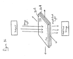
- a first modifier 702 is preferably stationary with respect to the film and located within a first plane.
- a second modifier 704 is selectively movable, preferably within a second plane that is adjacent and parallel to the first plane.
- Each modifier 702, 704 includes a textured, patterned, roughened, or otherwise distorted surface (either surface or includes internal distorting elements located within the modifier).
- second modifier 704 As second modifier 704 is moved with respect to first modifier 702, the image light from the subject will be continuously distorted in a somewhat unpredictable manner, thereby creating a variety of unusual and unique effects to the image light prior to the light being recorded on film.
- This variable distorting effect is somewhat similar to the distorting effect experienced when an image is viewed through two layers of screen. In this example, if one screen is moved slightly (depending on the size of the openings), the view image will appear different.
- a side sectional view of a camera 700 is shown, according to the example not part of the invention shown in Fig. 36 , having first (stationary) modifier 702, second (movable) modifier 704, a lens assembly 706, an eyepiece 708, a film gate 710, and film 712.
- first (stationary) modifier 702 second (movable) modifier 704, a lens assembly 706, an eyepiece 708, a film gate 710, and film 712.
- Second modifier 704 is mounted to camera 700 in such a manner to allow controlled movement (in this case up and down) with respect to film 712 and first modifier 702.
- a button 714 is attached to second modifier 704 by arm 716.
- a spring 718 is attached between second modifier 704 and camera 700 so that button 714 is biased to a rest position.
- a primary lens 750 including a primary lens 750, a first modifier 752, a second modifier 754, a third modifier 756, a relay lens 758, and film 760 (or digital input device, scanner, digitizer, etc.).
- any combination of modifiers 752, 754, 756 may be laterally displaced (each within a plane that is parallel to film 760), a selected amount.
- Primary lens focuses the image light from the subject to the modifiers 752, 754, 756. Once modified by all three modifiers, the image light is re-focused using relay lens 758 onto film 760.
- Relay lens 758 is only required if modifiers cannot be positioned adjacent to film 760, as described in earlier examples not part of this invention.
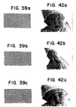
- Figs. 39a, 39b, and 39c are examples of first modifier 752, second modifier 754, and third modifier 756, respectively.
- either (or both) modifier 702, 704 may be mounted in a non-parallel orientation with respect to film 712. Although movement within either the second or first planes is preferred, either (or both) modifiers 702, 704 may be displaced or distorted in any plane, with respect to film 712 to create a variety of image distortions.
- modifiers 702, 704 be formed from a flat sheet of rigid or semi-rigid transparent material, such as plastic or glass, they may also be formed through an appropriate injection molding process and thereby be shaped curved or bent, or include 3-dimensional surface texture (e.g., a surface relief) to further vary image distortions.
- either (or both) modifiers 702, 704 may be formed from flexible transparent film (not shown) that is supplied on a roll within camera 700 and includes random or at least different distortions along its length.
- the film-type modifier (not shown) may be selectively moved past film gate 714 (e.g., rolled up similar to winding conventional film) so that a different distortion pattern or texture may be positioned in front of the yet to be exposed frame of film.
- light entering the camera may be modified by placing a modifier within film plane, in front of the film so that the recorded image is artistically distorted and altered, creating an unusual and aesthetically pleasing representation of the image, depending on the modifier used (e.g., an image may be altered to appear like an impressionistic painting of the subject).
- the sharpness of the modified light reaching the film may be controlled, thereby creating a variety of effects to a single image using a single modifier.
- the sharpness of the light modification may also be controlled by changing the main focus of the lens assembly 706.
- a fixed modifier 702 located adjacent to or within film gate 712 the operator first focuses onto a subject, then deliberately changes the focus a controlled amount (in either direction) within a prescribed range that can be indicated by indica located on the lens and/or camera (or similarly indicated using an appropriate electronic device).
- the focus of lens assembly 706 on the subject By changing the focus of lens assembly 706 on the subject, the image light entering the camera and representing the subject will be softened, defining the subject's contrast border lines with less sharpness and detail, resulting in a soft image.
- This "soft" light may be modified by modifier 702 and recorded on film. The degree of focus variation will determine the degree and characteristics of the modification by the modifier.
- the aperture of the lens may be also be varied to control the variations of modification.
- a camera 800 having a body 802 and a lens assembly 804.
- a lens attachment 806 is mounted to the exposed end of lens assembly 804 so that image light entering lens assembly 804, first passes through lens attachment 806.
- Lens attachment 806 includes a generally cylindrical housing 808 which supports at least one lens 810 (two are shown in the figure).
- Lens 810 is elastically mounted to housing 808 by mount 812 so that lens 810 remains in a rest position, but may be manually displaced within housing 808 in a somewhat random manner, by applying an internally directed force to mount 812 along an outer surface of housing 808, as indicated by arrows in Fig. 41 .
- mount 812 which is accessible on the outer surface of housing 808, so that lens 810 moves from its rest position, depending how mount 812 is squeezed and with how much force.
- mount 812 the image of the subject he views distorts, not unlike the distortion mirrors found at an amusement park.
- Mount 812 is preferably ring-shaped made from an appropriate semi-rigid to flexible rubber, such as silicone, and forms part of housing 808, as shown in Figs. 40 and 41 .
- Figures 42a-42c are examples of how the subject (a baby) may be distorted by displacing lens 810 within housing 808. It is preferred that lens 810 returns to the rest position after applied force to mount 812 is removed and that lens 810 does not distort (other than magnify) the image light when at the rest position within housing 808.
- lens 810 is positioned adjacent to another lens 811, which together with mount 812, defines an intermediate space 814.
- Either lens 811 or lens 810 (or both) is made from a semi-rigid plastic (such as the plastic used to make conventional contact lenses to correct myopia).
- a fluid such as an inert gas, or a transparent liquid is located within intermediate space 814. This fluid is sealed in intermediate space 814 by mount 812 (which is preferably flexible rubber).
- lens attachment 806 may alternately be provided integrally with lens assembly 804.
- a modifier may be positioned at an intermediate position, so that the projected image light is modified, in a manner described above, prior to the light exposing the paper (or downloaded to electronic memory).
- the modifier may be positioned within a slot located within the enlarger.
- a modifier as described above, may be used to distort the image light prior being "recorded" by an electronic scanner and downloaded into a computer.
- certain computer software programs are capable of electronically distorting a stored image, this process is very time consuming. Downloading a pre-modified image into the computer saves time and introduces effects that are not easily attainable using a computer program.
Landscapes
- Physics & Mathematics (AREA)
- General Physics & Mathematics (AREA)
- Structure And Mechanism Of Cameras (AREA)
Claims (7)
- Accessoire pour un appareil photographique pour modifier la lumière collective d'image réfléchie d'un sujet et pénétrant dans l'appareil photographique avant que l'image ainsi modifiée du sujet ne soit enregistrée sur le film, ledit appareil photographique ayant une ouverture d'objectif, un cadre d'image de film situé au niveau d'un plan du film, et un objectif, ledit accessoire comprenant :un plan focal intermédiaire situé à une distance prédéterminée dudit plan du film entre ledit plan du film et ledit sujet ;un moyen pour focaliser ladite lumière collective de ladite image sur ledit plan focal intermédiaire ;un modificateur optique transparent situé au niveau dudit plan focal intermédiaire ;un moyen pour distordre la lumière, ledit moyen de distorsion étant situé sur et formé de façon intégrale avec une surface dudit modificateur optique transparent, ledit moyen de distorsion étant transparent de façon à ce que ladite lumière provenant de ladite image soit distordue au niveau dudit plan focal intermédiaire sans être bloquée pour créer une image intermédiaire distordue focalisée ; etun moyen pour refocaliser ladite image intermédiaire distordue focalisée dudit plan focal intermédiaire sur ledit plan du film.
- Accessoire pour appareil photographique selon la revendication 1, comprenant en outre un moyen pour déplacer ledit modificateur optique transparent entre une première position dans laquelle ledit modificateur modifie une partie de ladite lumière provenant de ladite image et une deuxième position dans laquelle ladite lumière provenant de ladite image atteint ledit film sans modification.
- Accessoire pour appareil photographique selon la revendication 1, comprenant en outre un deuxième modificateur optique transparent et incluant un moyen pour positionner l'un dudit premier et dudit deuxième modificateurs optiques transparents dans ledit plan focal intermédiaire de façon à ce que ledit modificateur optique sélectionné modifie au moins une partie de ladite lumière provenant de ladite image avant que ladite lumière n'expose ledit film.
- Accessoire pour appareil photographique selon la revendication 3, dans lequel lesdits premier et deuxième modificateurs optiques transparents sont tous les deux montés sur un élément de transport mobile qui peut être déplacé à l'intérieur dudit plan focal intermédiaire entre une première position dans laquelle ledit premier modificateur optique modifie au moins une partie de ladite lumière provenant de ladite image et une deuxième position dans laquelle ledit deuxième modificateur optique modifie au moins une partie de ladite lumière provenant de ladite image.
- Accessoire pour appareil photographique selon la revendication 4, dans lequel ledit élément de transport inclut en outre une position dans laquelle ladite lumière provenant de ladite image atteint ledit film sans modification.
- Accessoire pour appareil photographique selon la revendication 5, dans lequel ledit élément de transport est une tourelle qui est rotative autour d'un point de pivot.
- Accessoire pour appareil photographique selon la revendication 5, dans lequel ledit élément de transport est une plaque allongée qui peut coulisser entre lesdites première et deuxième positions.
Applications Claiming Priority (2)
| Application Number | Priority Date | Filing Date | Title |
|---|---|---|---|
| US08/526,990 US5649259A (en) | 1995-09-12 | 1995-09-12 | Image modifiers for use in photography |
| PCT/US1997/008605 WO1998050825A1 (fr) | 1995-09-12 | 1997-05-09 | Modificateur d'images a usage photographique |
Publications (3)
| Publication Number | Publication Date |
|---|---|
| EP0980539A1 EP0980539A1 (fr) | 2000-02-23 |
| EP0980539A4 EP0980539A4 (fr) | 2006-11-02 |
| EP0980539B1 true EP0980539B1 (fr) | 2010-01-06 |
Family
ID=26792529
Family Applications (1)
| Application Number | Title | Priority Date | Filing Date |
|---|---|---|---|
| EP97925667A Expired - Lifetime EP0980539B1 (fr) | 1995-09-12 | 1997-05-09 | Modificateur d'images a usage photographique |
Country Status (4)
| Country | Link |
|---|---|
| US (1) | US5649259A (fr) |
| EP (1) | EP0980539B1 (fr) |
| AU (1) | AU3073897A (fr) |
| WO (1) | WO1998050825A1 (fr) |
Families Citing this family (8)
| Publication number | Priority date | Publication date | Assignee | Title |
|---|---|---|---|---|
| US6285834B1 (en) * | 1995-09-12 | 2001-09-04 | Smartlens Corporation | Image modifiers for use in photography |
| US6201933B1 (en) * | 1995-09-12 | 2001-03-13 | Smartlens Corporation | Image modifiers for use in photography |
| JP3673474B2 (ja) * | 1998-11-06 | 2005-07-20 | スマートレンズ・コーポレイション | 写真に使用する画像変形装置 |
| US6366740B1 (en) * | 1999-02-08 | 2002-04-02 | Fortunato Procopio | Apparatus and method for adapting a 35mm SLR still camera to a 35mm motion picture viewfinder |
| US6202040B1 (en) | 1999-05-20 | 2001-03-13 | The University Of Arizona | Image modifiers for use in scanning photographic images |
| US7391929B2 (en) * | 2000-02-11 | 2008-06-24 | Sony Corporation | Masking tool |
| JP2005513517A (ja) * | 2001-12-07 | 2005-05-12 | スマートレンズ・コーポレイション | 写真技術に使用するための選択的合焦システム |
| MX2022008965A (es) * | 2020-01-21 | 2022-08-15 | Freestyle Partners Llc | Dispositivo uv portatil y desechable con luz visible y optica de conformacion. |
Family Cites Families (13)
| Publication number | Priority date | Publication date | Assignee | Title |
|---|---|---|---|---|
| US1396035A (en) * | 1921-09-12 | 1921-11-08 | Eastman Kodak Co | Method of and apparatus for designating photographic exposures |
| US1773335A (en) * | 1922-06-21 | 1930-08-19 | Jr Adelbert Ames | Image modifier |
| GB593045A (en) * | 1942-06-20 | 1947-10-07 | Achille Pierre Dufour | Improvements in devices for taking moving pictures |
| US3665828A (en) * | 1970-06-01 | 1972-05-30 | Josef Reiter | Background photography |
| JPS5419174B2 (fr) * | 1973-06-15 | 1979-07-13 | ||
| CH622108A5 (fr) * | 1978-04-07 | 1981-03-13 | Zelacolor Syst | |
| US4304471A (en) * | 1979-04-23 | 1981-12-08 | Jones Mary R | Means for producing artistic borders on photographic prints, with or without appropriate wording |
| US4533224A (en) * | 1982-12-10 | 1985-08-06 | Ou Jan Chou | Multi-image camera |
| US4754297A (en) * | 1987-03-06 | 1988-06-28 | Edwards Clarence C | Camera and filter assembly |
| DE59103870D1 (de) * | 1990-08-17 | 1995-01-26 | Gretag Imaging Ag | Belichtungssteuerungsverfahren und fotografisches Kopiergerät. |
| US5247320A (en) * | 1992-03-11 | 1993-09-21 | Ct&T Promotions Nv | Process and apparatus for producing collage photographs |
| US5563675A (en) * | 1992-09-30 | 1996-10-08 | Lifetouch Portrait Studios, Inc. | Special effects carrier |
| US5550610A (en) * | 1995-08-09 | 1996-08-27 | Demarco; Frank G. | System for creating special effect images in the out-of-focus highlights of photographs |
-
1995
- 1995-09-12 US US08/526,990 patent/US5649259A/en not_active Expired - Lifetime
-
1997
- 1997-05-09 WO PCT/US1997/008605 patent/WO1998050825A1/fr not_active Ceased
- 1997-05-09 AU AU30738/97A patent/AU3073897A/en not_active Abandoned
- 1997-05-09 EP EP97925667A patent/EP0980539B1/fr not_active Expired - Lifetime
Also Published As
| Publication number | Publication date |
|---|---|
| AU3073897A (en) | 1998-11-27 |
| WO1998050825A1 (fr) | 1998-11-12 |
| US5649259A (en) | 1997-07-15 |
| EP0980539A1 (fr) | 2000-02-23 |
| EP0980539A4 (fr) | 2006-11-02 |
Similar Documents
| Publication | Publication Date | Title |
|---|---|---|
| US6167206A (en) | Image modifiers for use in photography | |
| US5570150A (en) | Stereo photographing system | |
| US3981565A (en) | Light-modulating device | |
| US5546146A (en) | Single use camera film pre-exposure method | |
| US6339680B1 (en) | Selectable multi-lens disposable camera | |
| US6285834B1 (en) | Image modifiers for use in photography | |
| AU3073897A (en) | Image modifiers for use in photography | |
| US6201933B1 (en) | Image modifiers for use in photography | |
| US4804992A (en) | Photographic film package | |
| JPH06317815A (ja) | 絞りプレート及びこれを用いたレンズ付きフイルムユニット | |
| US5021815A (en) | Viewfinder for tele/pan camera | |
| CA2291757C (fr) | Modificateur d'images a usage photographique | |
| EP1133714B1 (fr) | Modificateur d'image usage photographique | |
| US4107711A (en) | Photographic camera for taking three dimensional photographs and method and apparatus for forming trivision images | |
| KR20010012381A (ko) | 사진에서 사용하기 위한 이미지 변경자 | |
| MXPA99010246A (en) | Image modifiers for use in photography | |
| JPH05173004A (ja) | Ndフィルタの製造方法と絞り装置 | |
| US5070350A (en) | Field curvature effects minimized in tele/pan camera | |
| US4740812A (en) | Single channel masking camera & projector | |
| JP2007171988A (ja) | 写真技術に使用するための画像変形装置 | |
| JP2808750B2 (ja) | カメラ及びカメラ用シャッタユニット | |
| JPH04328537A (ja) | カメラ | |
| JP2627598B2 (ja) | カメラ | |
| JPH08184902A (ja) | 瞬間調光ガラスのカメラへの取付け構造 | |
| JPH08106112A (ja) | カメラ |
Legal Events
| Date | Code | Title | Description |
|---|---|---|---|
| PUAI | Public reference made under article 153(3) epc to a published international application that has entered the european phase |
Free format text: ORIGINAL CODE: 0009012 |
|
| 17P | Request for examination filed |
Effective date: 19991106 |
|
| AK | Designated contracting states |
Kind code of ref document: A1 Designated state(s): AT BE CH DE DK ES FI FR GB GR IE IT LI LU MC NL PT SE |
|
| RAP1 | Party data changed (applicant data changed or rights of an application transferred) |
Owner name: SMARTLENS CORPORATION |
|
| A4 | Supplementary search report drawn up and despatched |
Effective date: 20060929 |
|
| 17Q | First examination report despatched |
Effective date: 20070328 |
|
| GRAP | Despatch of communication of intention to grant a patent |
Free format text: ORIGINAL CODE: EPIDOSNIGR1 |
|
| GRAS | Grant fee paid |
Free format text: ORIGINAL CODE: EPIDOSNIGR3 |
|
| GRAA | (expected) grant |
Free format text: ORIGINAL CODE: 0009210 |
|
| AK | Designated contracting states |
Kind code of ref document: B1 Designated state(s): AT BE CH DE DK ES FI FR GB GR IE IT LI LU MC NL PT SE |
|
| REG | Reference to a national code |
Ref country code: GB Ref legal event code: FG4D |
|
| REG | Reference to a national code |
Ref country code: CH Ref legal event code: EP |
|
| REG | Reference to a national code |
Ref country code: IE Ref legal event code: FG4D |
|
| REF | Corresponds to: |
Ref document number: 69739735 Country of ref document: DE Date of ref document: 20100225 Kind code of ref document: P |
|
| REG | Reference to a national code |
Ref country code: NL Ref legal event code: VDEP Effective date: 20100106 |
|
| PG25 | Lapsed in a contracting state [announced via postgrant information from national office to epo] |
Ref country code: AT Free format text: LAPSE BECAUSE OF FAILURE TO SUBMIT A TRANSLATION OF THE DESCRIPTION OR TO PAY THE FEE WITHIN THE PRESCRIBED TIME-LIMIT Effective date: 20100106 |
|
| PG25 | Lapsed in a contracting state [announced via postgrant information from national office to epo] |
Ref country code: PT Free format text: LAPSE BECAUSE OF FAILURE TO SUBMIT A TRANSLATION OF THE DESCRIPTION OR TO PAY THE FEE WITHIN THE PRESCRIBED TIME-LIMIT Effective date: 20100506 Ref country code: NL Free format text: LAPSE BECAUSE OF FAILURE TO SUBMIT A TRANSLATION OF THE DESCRIPTION OR TO PAY THE FEE WITHIN THE PRESCRIBED TIME-LIMIT Effective date: 20100106 Ref country code: ES Free format text: LAPSE BECAUSE OF FAILURE TO SUBMIT A TRANSLATION OF THE DESCRIPTION OR TO PAY THE FEE WITHIN THE PRESCRIBED TIME-LIMIT Effective date: 20100417 |
|
| PG25 | Lapsed in a contracting state [announced via postgrant information from national office to epo] |
Ref country code: FI Free format text: LAPSE BECAUSE OF FAILURE TO SUBMIT A TRANSLATION OF THE DESCRIPTION OR TO PAY THE FEE WITHIN THE PRESCRIBED TIME-LIMIT Effective date: 20100106 |
|
| PG25 | Lapsed in a contracting state [announced via postgrant information from national office to epo] |
Ref country code: SE Free format text: LAPSE BECAUSE OF FAILURE TO SUBMIT A TRANSLATION OF THE DESCRIPTION OR TO PAY THE FEE WITHIN THE PRESCRIBED TIME-LIMIT Effective date: 20100106 Ref country code: GR Free format text: LAPSE BECAUSE OF FAILURE TO SUBMIT A TRANSLATION OF THE DESCRIPTION OR TO PAY THE FEE WITHIN THE PRESCRIBED TIME-LIMIT Effective date: 20100407 Ref country code: BE Free format text: LAPSE BECAUSE OF FAILURE TO SUBMIT A TRANSLATION OF THE DESCRIPTION OR TO PAY THE FEE WITHIN THE PRESCRIBED TIME-LIMIT Effective date: 20100106 |
|
| PLBE | No opposition filed within time limit |
Free format text: ORIGINAL CODE: 0009261 |
|
| STAA | Information on the status of an ep patent application or granted ep patent |
Free format text: STATUS: NO OPPOSITION FILED WITHIN TIME LIMIT |
|
| 26N | No opposition filed |
Effective date: 20101007 |
|
| PG25 | Lapsed in a contracting state [announced via postgrant information from national office to epo] |
Ref country code: MC Free format text: LAPSE BECAUSE OF NON-PAYMENT OF DUE FEES Effective date: 20100531 |
|
| REG | Reference to a national code |
Ref country code: CH Ref legal event code: PL |
|
| GBPC | Gb: european patent ceased through non-payment of renewal fee |
Effective date: 20100509 |
|
| PG25 | Lapsed in a contracting state [announced via postgrant information from national office to epo] |
Ref country code: DK Free format text: LAPSE BECAUSE OF FAILURE TO SUBMIT A TRANSLATION OF THE DESCRIPTION OR TO PAY THE FEE WITHIN THE PRESCRIBED TIME-LIMIT Effective date: 20100106 |
|
| REG | Reference to a national code |
Ref country code: FR Ref legal event code: ST Effective date: 20110131 |
|
| PG25 | Lapsed in a contracting state [announced via postgrant information from national office to epo] |
Ref country code: LI Free format text: LAPSE BECAUSE OF NON-PAYMENT OF DUE FEES Effective date: 20100531 Ref country code: CH Free format text: LAPSE BECAUSE OF NON-PAYMENT OF DUE FEES Effective date: 20100531 |
|
| PG25 | Lapsed in a contracting state [announced via postgrant information from national office to epo] |
Ref country code: IT Free format text: LAPSE BECAUSE OF FAILURE TO SUBMIT A TRANSLATION OF THE DESCRIPTION OR TO PAY THE FEE WITHIN THE PRESCRIBED TIME-LIMIT Effective date: 20100106 |
|
| PG25 | Lapsed in a contracting state [announced via postgrant information from national office to epo] |
Ref country code: DE Free format text: LAPSE BECAUSE OF NON-PAYMENT OF DUE FEES Effective date: 20101201 Ref country code: IE Free format text: LAPSE BECAUSE OF NON-PAYMENT OF DUE FEES Effective date: 20100509 |
|
| PG25 | Lapsed in a contracting state [announced via postgrant information from national office to epo] |
Ref country code: FR Free format text: LAPSE BECAUSE OF NON-PAYMENT OF DUE FEES Effective date: 20100531 |
|
| PG25 | Lapsed in a contracting state [announced via postgrant information from national office to epo] |
Ref country code: GB Free format text: LAPSE BECAUSE OF NON-PAYMENT OF DUE FEES Effective date: 20100509 |
|
| PG25 | Lapsed in a contracting state [announced via postgrant information from national office to epo] |
Ref country code: LU Free format text: LAPSE BECAUSE OF NON-PAYMENT OF DUE FEES Effective date: 20100509 |