EP0980776A2 - Antriebseinrichtung für Schiebetüren von Kraftfahrzeugen - Google Patents
Antriebseinrichtung für Schiebetüren von Kraftfahrzeugen Download PDFInfo
- Publication number
- EP0980776A2 EP0980776A2 EP99202102A EP99202102A EP0980776A2 EP 0980776 A2 EP0980776 A2 EP 0980776A2 EP 99202102 A EP99202102 A EP 99202102A EP 99202102 A EP99202102 A EP 99202102A EP 0980776 A2 EP0980776 A2 EP 0980776A2
- Authority
- EP
- European Patent Office
- Prior art keywords
- motor
- transmission
- drive apparatus
- gear wheel
- accordance
- Prior art date
- Legal status (The legal status is an assumption and is not a legal conclusion. Google has not performed a legal analysis and makes no representation as to the accuracy of the status listed.)
- Withdrawn
Links
Images
Classifications
-
- E—FIXED CONSTRUCTIONS
- E05—LOCKS; KEYS; WINDOW OR DOOR FITTINGS; SAFES
- E05F—DEVICES FOR MOVING WINGS INTO OPEN OR CLOSED POSITION; CHECKS FOR WINGS; WING FITTINGS NOT OTHERWISE PROVIDED FOR, CONCERNED WITH THE FUNCTIONING OF THE WING
- E05F15/00—Power-operated mechanisms for wings
- E05F15/60—Power-operated mechanisms for wings using electrical actuators
- E05F15/603—Power-operated mechanisms for wings using electrical actuators using rotary electromotors
- E05F15/632—Power-operated mechanisms for wings using electrical actuators using rotary electromotors for horizontally-sliding wings
-
- E—FIXED CONSTRUCTIONS
- E05—LOCKS; KEYS; WINDOW OR DOOR FITTINGS; SAFES
- E05F—DEVICES FOR MOVING WINGS INTO OPEN OR CLOSED POSITION; CHECKS FOR WINGS; WING FITTINGS NOT OTHERWISE PROVIDED FOR, CONCERNED WITH THE FUNCTIONING OF THE WING
- E05F15/00—Power-operated mechanisms for wings
- E05F15/60—Power-operated mechanisms for wings using electrical actuators
- E05F15/603—Power-operated mechanisms for wings using electrical actuators using rotary electromotors
-
- F—MECHANICAL ENGINEERING; LIGHTING; HEATING; WEAPONS; BLASTING
- F16—ENGINEERING ELEMENTS AND UNITS; GENERAL MEASURES FOR PRODUCING AND MAINTAINING EFFECTIVE FUNCTIONING OF MACHINES OR INSTALLATIONS; THERMAL INSULATION IN GENERAL
- F16H—GEARING
- F16H1/00—Toothed gearings for conveying rotary motion
- F16H1/28—Toothed gearings for conveying rotary motion with gears having orbital motion
- F16H1/32—Toothed gearings for conveying rotary motion with gears having orbital motion in which the central axis of the gearing lies inside the periphery of an orbital gear
-
- E—FIXED CONSTRUCTIONS
- E05—LOCKS; KEYS; WINDOW OR DOOR FITTINGS; SAFES
- E05Y—INDEXING SCHEME ASSOCIATED WITH SUBCLASSES E05D AND E05F, RELATING TO CONSTRUCTION ELEMENTS, ELECTRIC CONTROL, POWER SUPPLY, POWER SIGNAL OR TRANSMISSION, USER INTERFACES, MOUNTING OR COUPLING, DETAILS, ACCESSORIES, AUXILIARY OPERATIONS NOT OTHERWISE PROVIDED FOR, APPLICATION THEREOF
- E05Y2201/00—Constructional elements; Accessories therefor
- E05Y2201/20—Brakes; Disengaging means; Holders; Stops; Valves; Accessories therefor
- E05Y2201/214—Disengaging means
- E05Y2201/216—Clutches
-
- E—FIXED CONSTRUCTIONS
- E05—LOCKS; KEYS; WINDOW OR DOOR FITTINGS; SAFES
- E05Y—INDEXING SCHEME ASSOCIATED WITH SUBCLASSES E05D AND E05F, RELATING TO CONSTRUCTION ELEMENTS, ELECTRIC CONTROL, POWER SUPPLY, POWER SIGNAL OR TRANSMISSION, USER INTERFACES, MOUNTING OR COUPLING, DETAILS, ACCESSORIES, AUXILIARY OPERATIONS NOT OTHERWISE PROVIDED FOR, APPLICATION THEREOF
- E05Y2201/00—Constructional elements; Accessories therefor
- E05Y2201/20—Brakes; Disengaging means; Holders; Stops; Valves; Accessories therefor
- E05Y2201/23—Actuation thereof
- E05Y2201/246—Actuation thereof by auxiliary motors, magnets, springs or weights
-
- E—FIXED CONSTRUCTIONS
- E05—LOCKS; KEYS; WINDOW OR DOOR FITTINGS; SAFES
- E05Y—INDEXING SCHEME ASSOCIATED WITH SUBCLASSES E05D AND E05F, RELATING TO CONSTRUCTION ELEMENTS, ELECTRIC CONTROL, POWER SUPPLY, POWER SIGNAL OR TRANSMISSION, USER INTERFACES, MOUNTING OR COUPLING, DETAILS, ACCESSORIES, AUXILIARY OPERATIONS NOT OTHERWISE PROVIDED FOR, APPLICATION THEREOF
- E05Y2201/00—Constructional elements; Accessories therefor
- E05Y2201/40—Motors; Magnets; Springs; Weights; Accessories therefor
- E05Y2201/43—Motors
- E05Y2201/434—Electromotors; Details thereof
-
- E—FIXED CONSTRUCTIONS
- E05—LOCKS; KEYS; WINDOW OR DOOR FITTINGS; SAFES
- E05Y—INDEXING SCHEME ASSOCIATED WITH SUBCLASSES E05D AND E05F, RELATING TO CONSTRUCTION ELEMENTS, ELECTRIC CONTROL, POWER SUPPLY, POWER SIGNAL OR TRANSMISSION, USER INTERFACES, MOUNTING OR COUPLING, DETAILS, ACCESSORIES, AUXILIARY OPERATIONS NOT OTHERWISE PROVIDED FOR, APPLICATION THEREOF
- E05Y2201/00—Constructional elements; Accessories therefor
- E05Y2201/40—Motors; Magnets; Springs; Weights; Accessories therefor
- E05Y2201/46—Magnets
- E05Y2201/462—Electromagnets
-
- E—FIXED CONSTRUCTIONS
- E05—LOCKS; KEYS; WINDOW OR DOOR FITTINGS; SAFES
- E05Y—INDEXING SCHEME ASSOCIATED WITH SUBCLASSES E05D AND E05F, RELATING TO CONSTRUCTION ELEMENTS, ELECTRIC CONTROL, POWER SUPPLY, POWER SIGNAL OR TRANSMISSION, USER INTERFACES, MOUNTING OR COUPLING, DETAILS, ACCESSORIES, AUXILIARY OPERATIONS NOT OTHERWISE PROVIDED FOR, APPLICATION THEREOF
- E05Y2201/00—Constructional elements; Accessories therefor
- E05Y2201/60—Suspension or transmission members; Accessories therefor
- E05Y2201/606—Accessories therefor
- E05Y2201/618—Transmission ratio variation
-
- E—FIXED CONSTRUCTIONS
- E05—LOCKS; KEYS; WINDOW OR DOOR FITTINGS; SAFES
- E05Y—INDEXING SCHEME ASSOCIATED WITH SUBCLASSES E05D AND E05F, RELATING TO CONSTRUCTION ELEMENTS, ELECTRIC CONTROL, POWER SUPPLY, POWER SIGNAL OR TRANSMISSION, USER INTERFACES, MOUNTING OR COUPLING, DETAILS, ACCESSORIES, AUXILIARY OPERATIONS NOT OTHERWISE PROVIDED FOR, APPLICATION THEREOF
- E05Y2201/00—Constructional elements; Accessories therefor
- E05Y2201/60—Suspension or transmission members; Accessories therefor
- E05Y2201/622—Suspension or transmission members elements
- E05Y2201/71—Toothed gearing
- E05Y2201/716—Pinions
-
- E—FIXED CONSTRUCTIONS
- E05—LOCKS; KEYS; WINDOW OR DOOR FITTINGS; SAFES
- E05Y—INDEXING SCHEME ASSOCIATED WITH SUBCLASSES E05D AND E05F, RELATING TO CONSTRUCTION ELEMENTS, ELECTRIC CONTROL, POWER SUPPLY, POWER SIGNAL OR TRANSMISSION, USER INTERFACES, MOUNTING OR COUPLING, DETAILS, ACCESSORIES, AUXILIARY OPERATIONS NOT OTHERWISE PROVIDED FOR, APPLICATION THEREOF
- E05Y2201/00—Constructional elements; Accessories therefor
- E05Y2201/60—Suspension or transmission members; Accessories therefor
- E05Y2201/622—Suspension or transmission members elements
- E05Y2201/71—Toothed gearing
- E05Y2201/72—Planetary gearing
-
- E—FIXED CONSTRUCTIONS
- E05—LOCKS; KEYS; WINDOW OR DOOR FITTINGS; SAFES
- E05Y—INDEXING SCHEME ASSOCIATED WITH SUBCLASSES E05D AND E05F, RELATING TO CONSTRUCTION ELEMENTS, ELECTRIC CONTROL, POWER SUPPLY, POWER SIGNAL OR TRANSMISSION, USER INTERFACES, MOUNTING OR COUPLING, DETAILS, ACCESSORIES, AUXILIARY OPERATIONS NOT OTHERWISE PROVIDED FOR, APPLICATION THEREOF
- E05Y2400/00—Electronic control; Electrical power; Power supply; Power or signal transmission; User interfaces
- E05Y2400/10—Electronic control
- E05Y2400/30—Electronic control of motors
- E05Y2400/3013—Electronic control of motors during manual wing operation
- E05Y2400/3014—Back driving the transmission or motor
-
- E—FIXED CONSTRUCTIONS
- E05—LOCKS; KEYS; WINDOW OR DOOR FITTINGS; SAFES
- E05Y—INDEXING SCHEME ASSOCIATED WITH SUBCLASSES E05D AND E05F, RELATING TO CONSTRUCTION ELEMENTS, ELECTRIC CONTROL, POWER SUPPLY, POWER SIGNAL OR TRANSMISSION, USER INTERFACES, MOUNTING OR COUPLING, DETAILS, ACCESSORIES, AUXILIARY OPERATIONS NOT OTHERWISE PROVIDED FOR, APPLICATION THEREOF
- E05Y2400/00—Electronic control; Electrical power; Power supply; Power or signal transmission; User interfaces
- E05Y2400/10—Electronic control
- E05Y2400/30—Electronic control of motors
- E05Y2400/3013—Electronic control of motors during manual wing operation
- E05Y2400/3015—Power assistance
-
- E—FIXED CONSTRUCTIONS
- E05—LOCKS; KEYS; WINDOW OR DOOR FITTINGS; SAFES
- E05Y—INDEXING SCHEME ASSOCIATED WITH SUBCLASSES E05D AND E05F, RELATING TO CONSTRUCTION ELEMENTS, ELECTRIC CONTROL, POWER SUPPLY, POWER SIGNAL OR TRANSMISSION, USER INTERFACES, MOUNTING OR COUPLING, DETAILS, ACCESSORIES, AUXILIARY OPERATIONS NOT OTHERWISE PROVIDED FOR, APPLICATION THEREOF
- E05Y2400/00—Electronic control; Electrical power; Power supply; Power or signal transmission; User interfaces
- E05Y2400/10—Electronic control
- E05Y2400/44—Sensors not directly associated with the wing movement
-
- E—FIXED CONSTRUCTIONS
- E05—LOCKS; KEYS; WINDOW OR DOOR FITTINGS; SAFES
- E05Y—INDEXING SCHEME ASSOCIATED WITH SUBCLASSES E05D AND E05F, RELATING TO CONSTRUCTION ELEMENTS, ELECTRIC CONTROL, POWER SUPPLY, POWER SIGNAL OR TRANSMISSION, USER INTERFACES, MOUNTING OR COUPLING, DETAILS, ACCESSORIES, AUXILIARY OPERATIONS NOT OTHERWISE PROVIDED FOR, APPLICATION THEREOF
- E05Y2600/00—Mounting or coupling arrangements for elements provided for in this subclass
- E05Y2600/40—Mounting location; Visibility of the elements
- E05Y2600/454—Mounting location; Visibility of the elements in or on the motor
-
- E—FIXED CONSTRUCTIONS
- E05—LOCKS; KEYS; WINDOW OR DOOR FITTINGS; SAFES
- E05Y—INDEXING SCHEME ASSOCIATED WITH SUBCLASSES E05D AND E05F, RELATING TO CONSTRUCTION ELEMENTS, ELECTRIC CONTROL, POWER SUPPLY, POWER SIGNAL OR TRANSMISSION, USER INTERFACES, MOUNTING OR COUPLING, DETAILS, ACCESSORIES, AUXILIARY OPERATIONS NOT OTHERWISE PROVIDED FOR, APPLICATION THEREOF
- E05Y2800/00—Details, accessories and auxiliary operations not otherwise provided for
- E05Y2800/26—Form or shape
- E05Y2800/268—Form or shape cylindrical; disc-shaped; circular
-
- E—FIXED CONSTRUCTIONS
- E05—LOCKS; KEYS; WINDOW OR DOOR FITTINGS; SAFES
- E05Y—INDEXING SCHEME ASSOCIATED WITH SUBCLASSES E05D AND E05F, RELATING TO CONSTRUCTION ELEMENTS, ELECTRIC CONTROL, POWER SUPPLY, POWER SIGNAL OR TRANSMISSION, USER INTERFACES, MOUNTING OR COUPLING, DETAILS, ACCESSORIES, AUXILIARY OPERATIONS NOT OTHERWISE PROVIDED FOR, APPLICATION THEREOF
- E05Y2900/00—Application of doors, windows, wings or fittings thereof
- E05Y2900/50—Application of doors, windows, wings or fittings thereof for vehicles
- E05Y2900/53—Type of wing
- E05Y2900/531—Doors
Definitions
- the present invention relates to a drive apparatus, in particular for the automatic actuation of a sliding door of a motor vehicle.
- Such drive apparatuses normally operate with an electric motor and a step-down transmission.
- the small amount of space available in the region of the door proves to be problematic.
- it must be ensured that the door can also be moved manually with as little force as possible.
- the object of the invention is to set forth a drive apparatus of the initially named kind which has a low space requirement and enables easy manual movement of the door.
- a drive apparatus having a fast running motor, the motor shaft of which is connected to a transmission with a large step-down ratio, the transmission having a first gear wheel which can be secured against rotation, via a releasable blocking device, and a second rotatable gear wheel which is rotationally fixedly connected to an output drive shaft and which is rotatable relative to the first gear wheel by the rotation of the motor when the first gear wheel is blocked, with the number of teeth of the first gear wheel only differing by a few teeth from the number of teeth of the second gear wheel and with the large step-down ratio being determined by this difference of the tooth numbers.
- the high step-down ratio of the transmission can also be changed to a 1:1 ratio.
- the transmission can thereby by driven in reverse, so that the sliding door can be actuated manually without it being necessary to provide a releasable clutch device between the sliding door and the drive apparatus as in the known drive apparatuses. Through this, both the space required and the costs are also reduced.
- the transmission of the drive apparatus of the invention is preferably formed in the manner of a so-called harmonic drive or flex drive transmission comprising a hollow gear having an inner toothed ring, the so-called circular spline, and a flexible ring with an outer toothed rim, the so-called flex spline, arranged therein, with the circular spline being releasably fixable against rotation via the releasable blocking device and with the flex spline being rotationally fixedly connected to the output drive shaft or vice versa.
- a so-called harmonic drive or flex drive transmission comprising a hollow gear having an inner toothed ring, the so-called circular spline, and a flexible ring with an outer toothed rim, the so-called flex spline, arranged therein, with the circular spline being releasably fixable against rotation via the releasable blocking device and with the flex spline being rotationally fixedly connected to the output
- the transmission is formed in the manner of a cyclo transmission comprising a rigid hollow gear, having an inner ring of teeth and a cam disc arranged therein which can be moved by means of an eccentric device, with the hollow gear being capable of being secured against rotation via the releasable blocking device and the cam disc being rotationally fixedly connected to the output drive shaft or vice versa.
- a cyclo transmission comprising a rigid hollow gear, having an inner ring of teeth and a cam disc arranged therein which can be moved by means of an eccentric device, with the hollow gear being capable of being secured against rotation via the releasable blocking device and the cam disc being rotationally fixedly connected to the output drive shaft or vice versa.
- the blocking device is electrically actuatable.
- the blocking device is preferably automatically actuated together with the motor. In this way the operation of the drive apparatus can be realised in a simple manner with a high step-down ratio through actuation of the blocking device and with a low step-down ratio on releasing the blocking device.
- the blocking device operates electromagnetically.
- the blocking device can in particular be formed as an electromagnetic brake. This is not complicated design-wise and is very reliable in operation.
- a sensor is present for detecting a motor rotation. It can be advantageously determined via the sensor whether the sliding door is moving because, in the drive apparatus of the invention which does not require a coupling device, the motor always turns when the sliding door is moving.
- the sensor is preferably integrated into the motor and is thereby better protected against environmental influences.
- the motor is formed as a disc armature or pancake motor. This is a very cost-favourable quick running type of motor. As a result of the high step-down ratio of the transmission used for the drive apparatus of the invention, this motor can be used without problem and the manufacturing costs of the apparatus can be lowered in this way.
- the transmission drives a drum onto which and from which a draw means, in particular a draw cable, can be wound and unwound.
- a draw means in particular a draw cable
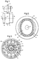
- the drive apparatus shown in Fig. 1 includes a motor 1 which is in particular formed as a disc armature or pancake motor, with the motor shaft 2 of the motor 1 being connected to a transmission 3.
- the transmission 3 has an output drive gear 4 with outer teeth 5 and a blocking device 6 which is in particular formed as an electromagnetic brake.
- the outer teeth 5 of the output drive gear 4 stand in engagement with the outer teeth 7 of a ring of teeth 8 on a drum 9 which is rotatably journalled about an axis II.
- a non-illustrated draw cable 9 can be wound onto and unwound from the drum 9 and acts in turn on a sliding door of a motor vehicle, which is likewise not illustrated. An activation of the motor 1 thus leads to an actuation of the sliding door by rotation of the drum 9.
- the transmission 3, which is not shown in more detail in Fig. 1, can, for example, be formed in the manner shown in Fig. 2.
- the basic layout thereby corresponds to a so-called harmonic drive or flex drive transmission of a type known per se.
- a flexible ring 12 with outer teeth 13 is arranged within a rigid hollow gear 10 having inner teeth 11.
- the number of teeth of the inner toothed arrangement 11 is selected to differ from the number of teeth of the outer toothed arrangement 13.
- the inner toothed arrangement 11 has 52 teeth and the outer toothed arrangement 13 has 50 teeth.
- An elliptical body 14 is rotatably journalled within the flexible ring 12 about an axis which corresponds to the motor axis I.
- the elliptical body 14 is rotationally fixedly connected to the motor shaft 2.
- a ball bearing 15 is provided between the elliptical body and the flexible ring 12.
- the rigid hollow gear 10 is likewise rotatably journalled about the axis 1, but can be blocked via the blocking device 6 against rotation.
- the blocking device 6 On activating the motor 1, the blocking device 6 is automatically actuated at the same time and the hollow gear is thereby blocked.
- the elliptical body 14 rotates and brings the teeth of the outer toothed arrangement 13 of the flexible ring 12 into engagement with the teeth of the inner toothed arrangement 11 of the hollow gear 10 in each case in the region of the main axis of the ellipse.
- the flexible ring 12 thus rotates about the axis I.
- the function corresponds to that of a known harmonic drive transmission.
- the flexible ring 12 rotates by one tooth relative to the hollow gear 10, i.e. about the axis I, on a rotation of the motor shaft 2, and thus of the elliptical body 14, through 180°. With a full rotation the flexible ring moves on by two teeth. In this way, a step-down ratio of 1:25 arises.
- the step-down ratio generally corresponds to the difference of the number of teeth divided by the total number of the teeth of the flexible ring 12.
- the flexible ring 12 is coaxially arranged relative to the output drive gear 4 and rotationally fixedly connected thereto.
- the rotation of the output drive gear 4 thus corresponds to the rotation of the flexible ring 12.
- the blocking device 6 On stopping the electric motor 1, the blocking device 6 is also released.
- the hollow gear 10 can now be rotated about the axis I.
- the hollow gear 10 On manual shifting of the sliding door, the hollow gear 10 now rotates, together with the flexible ring 12, about the axis I. In this way the motor is driven with a transmission ratio of 1:1.
- the transmission of the invention can thus be driven backwardly.
- a sensor 16 can finally be provided in the area of the motor and detects a rotation of the motor 1 about the axis I.
- This can, for example, be a sensor which operates with light.
- the motor 1 is, namely, turned about the axis I on manual actuation of the sliding door, as a result of the design of the drive apparatus without a clutch in accordance with the invention.
- the manual actuation can thus be detected simply in this manner, by means of the sensor, in particular in order to activate the motor 1 to assist the door movement.
- the invention can be realised with the transmission shown in Fig. 3 which corresponds from its basic layout to a cyclo (or cycloidal) transmission known per se.
- the output drive gear 4 is then connected via pins 17 to the inwardly disposed cam disc 18 of the cyclo transmission, while the outer hollow gear 10 can be fixed via the blocking device 6 for the motor operation and can be released for manual actuation, so that the transmission can also be driven backwardly here when the motor is stopped.
- the cam disc 18 is in other respects moved via the motor shaft 2 by means of an eccentric element 19 through the intermediary of a ball bearing 20.
- the hollow gear 10 could also, in each case, basically be rotationally fixedly connected to the output drive gear 4 and, in exchange, the flexible ring 12 or the inner cam disc 18 of the cyclo transmission can be fixed via the blocking device 6 against a rotation about the motor axis I.
- a high step-down ratio also results in motor operation and a ratio of 1:1 during manual operation, so that the transmission can be driven backwardly.
Landscapes
- Engineering & Computer Science (AREA)
- General Engineering & Computer Science (AREA)
- Mechanical Engineering (AREA)
- Power-Operated Mechanisms For Wings (AREA)
Applications Claiming Priority (2)
| Application Number | Priority Date | Filing Date | Title |
|---|---|---|---|
| US09/126,127 US6100619A (en) | 1998-07-30 | 1998-07-30 | Drive apparatus, in particular for a sliding door of a motor vehicle |
| US126127 | 1998-07-30 |
Publications (2)
| Publication Number | Publication Date |
|---|---|
| EP0980776A2 true EP0980776A2 (de) | 2000-02-23 |
| EP0980776A3 EP0980776A3 (de) | 2000-10-11 |
Family
ID=22423124
Family Applications (1)
| Application Number | Title | Priority Date | Filing Date |
|---|---|---|---|
| EP99202102A Withdrawn EP0980776A3 (de) | 1998-07-30 | 1999-06-29 | Antriebseinrichtung für Schiebetüren von Kraftfahrzeugen |
Country Status (2)
| Country | Link |
|---|---|
| US (1) | US6100619A (de) |
| EP (1) | EP0980776A3 (de) |
Cited By (4)
| Publication number | Priority date | Publication date | Assignee | Title |
|---|---|---|---|---|
| WO2006008280A1 (de) * | 2004-07-20 | 2006-01-26 | Witte-Velbert Gmbh & Co. Kg | Getriebeanordnung zum öffnen / schliessen einer tür, einer klappe oder dergleichen |
| US7243461B2 (en) | 2003-03-19 | 2007-07-17 | Rogers Jr Lloyd W | Hinge mechanism for a sliding door |
| US7325361B2 (en) | 2003-03-19 | 2008-02-05 | Delphi Technologies, Inc. | Apparatus and method for providing a modular sliding door mechanism |
| US10337216B2 (en) | 2014-01-02 | 2019-07-02 | Strattec Power Access Llc | Vehicle door |
Families Citing this family (17)
| Publication number | Priority date | Publication date | Assignee | Title |
|---|---|---|---|---|
| DE10024907B4 (de) * | 2000-05-16 | 2004-05-27 | Brose Fahrzeugteile Gmbh & Co. Kg, Coburg | Antriebseinheit |
| US6566777B2 (en) * | 2001-10-05 | 2003-05-20 | Abuakeel Hadi | Elastic wave actuator |
| AU2002365178A1 (en) * | 2002-10-28 | 2004-05-25 | Abu Akeel Hadi | Elastic wave actuator |
| US6848216B2 (en) * | 2003-02-27 | 2005-02-01 | Arvinmeritor Technology Llc | Single drive system for driving components of sliding vehicle closure member |
| US6854212B2 (en) * | 2003-03-06 | 2005-02-15 | Arvinmeritor Technology, Llc. | Belt drive system for sliding vehicle door |
| US9523231B2 (en) | 2003-11-10 | 2016-12-20 | Strattec Power Access Llc | Attachment assembly and drive unit having same |
| US7144068B2 (en) * | 2003-11-20 | 2006-12-05 | Intier Automotive Closures Inc. | Drive mechanism for selectively opening and closing a closure panel manually or automatically |
| EP1713160B1 (de) * | 2005-04-11 | 2020-06-17 | Delphi Technologies, Inc. | Antriebsvorrichtung für eine motorisch verstellbare Kraftfahrzeugtür mit einem Bewegungsdetektor |
| US7852183B2 (en) * | 2005-11-14 | 2010-12-14 | Honeywell International Inc. | Power drive unit electromagnetic latch |
| ATE455924T1 (de) * | 2007-03-12 | 2010-02-15 | Delphi Tech Inc | Türbetätigungsverfahren |
| DE102007023712B4 (de) * | 2007-05-22 | 2010-12-30 | Bühler Motor GmbH | Antrieb mit einem Elektromotor, einem Gehäuse und einer richtungsabhängigen Bremse |
| US7777385B2 (en) * | 2008-05-15 | 2010-08-17 | Honeywell International Inc. | Compact, electromagnetically braked actuator assembly |
| DE102009053727A1 (de) * | 2009-11-18 | 2011-05-19 | Audi Ag | Zykloidgetriebe |
| US9783027B1 (en) | 2016-04-12 | 2017-10-10 | Ford Global Technologies, Llc | Vehicle door assist assembly incorporating a high torque operating mechanism |
| JP6918343B2 (ja) * | 2017-05-22 | 2021-08-11 | Skg株式会社 | 回転減速伝達装置 |
| GB201716311D0 (en) * | 2017-10-05 | 2017-11-22 | Freeflow Tech Limited | Apparatus and Method |
| DE102017220326B4 (de) * | 2017-11-15 | 2022-10-06 | Ford Global Technologies, Llc | Verfahren zum Betrieb einer Motorantriebsvorrichtung einer Fahrzeugschiebetür |
Family Cites Families (18)
| Publication number | Priority date | Publication date | Assignee | Title |
|---|---|---|---|---|
| US3457674A (en) * | 1967-03-22 | 1969-07-29 | Gyro Tech Door Co | Automatic balanced door operator |
| US3495108A (en) * | 1968-03-19 | 1970-02-10 | Us Navy | Self-contained servomechanism |
| US4227092A (en) * | 1977-11-30 | 1980-10-07 | The United States Of America As Represented By The Secretary Of The Army | Hand cranked electrical power source |
| CA1244855A (en) * | 1985-01-18 | 1988-11-15 | Kazuyuki Matsumoto | Robot arm drive apparatus of industrial robot |
| US4862640A (en) * | 1987-12-18 | 1989-09-05 | Masco Industries, Inc. | Powered sliding door opener/closer for vehicles |
| US4984385A (en) * | 1990-03-22 | 1991-01-15 | Masco Industries, Inc. | Powered closing assist mechanism for vehicle doors or lid members |
| JPH0749746B2 (ja) * | 1990-06-29 | 1995-05-31 | 株式会社大井製作所 | スライドドアの自動開閉装置 |
| US5221239A (en) * | 1990-09-17 | 1993-06-22 | Overhead Door Corporation, Horton Automatics Division | Automatic door operator with compound epicyclic gear drive system |
| JP2901424B2 (ja) * | 1992-08-06 | 1999-06-07 | 住友重機械工業株式会社 | 低速ギヤドモータ |
| DK0619638T3 (da) * | 1993-04-03 | 1999-04-12 | Knoerzer Karl Heinz | Elektrisk skiverotormaskine |
| US5551190A (en) * | 1993-05-19 | 1996-09-03 | Ohi Seisakusho Co., Ltd. | Slide door driving system |
| DE4332323C2 (de) * | 1993-09-23 | 1995-11-30 | Leybold Ag | Getriebemotor mit einem eine Hohlwelle aufweisenden Elektromotor |
| WO1995026701A1 (en) * | 1994-03-30 | 1995-10-12 | Lumex, Inc. | Exercise method and apparatus with cycloidal reducer |
| US5613321A (en) * | 1994-08-30 | 1997-03-25 | Ricon Corporation | Releasable drive mechanism |
| DE19532808C1 (de) * | 1995-08-25 | 1997-01-02 | Brose Fahrzeugteile | Antriebseinrichtung für bewegliche Bauteile in Kraftfahrzeugen |
| US5643128A (en) * | 1996-02-01 | 1997-07-01 | Ami Industries | Harmonic drive using guided, floating cam driven cylinders as power transmitting elements |
| US5755059A (en) * | 1996-05-01 | 1998-05-26 | Itt Automotive Electrical Systems, Inc. | Solenoid operated clutch for powered sliding door |
| US5831358A (en) * | 1997-09-30 | 1998-11-03 | General Electric Company | Rotor end cap |
-
1998
- 1998-07-30 US US09/126,127 patent/US6100619A/en not_active Expired - Fee Related
-
1999
- 1999-06-29 EP EP99202102A patent/EP0980776A3/de not_active Withdrawn
Cited By (5)
| Publication number | Priority date | Publication date | Assignee | Title |
|---|---|---|---|---|
| US7243461B2 (en) | 2003-03-19 | 2007-07-17 | Rogers Jr Lloyd W | Hinge mechanism for a sliding door |
| US7325361B2 (en) | 2003-03-19 | 2008-02-05 | Delphi Technologies, Inc. | Apparatus and method for providing a modular sliding door mechanism |
| WO2006008280A1 (de) * | 2004-07-20 | 2006-01-26 | Witte-Velbert Gmbh & Co. Kg | Getriebeanordnung zum öffnen / schliessen einer tür, einer klappe oder dergleichen |
| DE102004051767B4 (de) | 2004-07-20 | 2018-03-29 | Witte-Velbert Gmbh & Co. Kg | Getriebeanordnung zum Öffnen/Schließen einer Tür, einer Klappe o. dgl. |
| US10337216B2 (en) | 2014-01-02 | 2019-07-02 | Strattec Power Access Llc | Vehicle door |
Also Published As
| Publication number | Publication date |
|---|---|
| EP0980776A3 (de) | 2000-10-11 |
| US6100619A (en) | 2000-08-08 |
Similar Documents
| Publication | Publication Date | Title |
|---|---|---|
| US6100619A (en) | Drive apparatus, in particular for a sliding door of a motor vehicle | |
| CN1221423C (zh) | 用于操纵车辆驻车制动器的驱动装置 | |
| US4765425A (en) | Electric power steering apparatus | |
| IL171664A (en) | Steerable/ retractable cargo power drive unit | |
| US20120204663A1 (en) | Vehicle door driving apparatus | |
| TW201726482A (zh) | 自行車用驅動裝置 | |
| EP0742127A3 (de) | Startsteuerung für Fahrzeuge | |
| JP2023533322A (ja) | デュアル動力源駆動減速機用のデフロック及びパーキング構造 | |
| US7584572B2 (en) | Driving apparatus for vehicle door | |
| JPS62295776A (ja) | 電気式パワ−ステアリング装置 | |
| CA3077740A1 (en) | Hinge-based door control system | |
| US7357751B2 (en) | Drive for pivoting a flap arranged on a body of a vehicle about a pivot axis | |
| US20100097745A1 (en) | Cover closer | |
| WO1991008403A1 (en) | Stop and start reversing mechanism for a motor drive | |
| US12467510B2 (en) | Electronic parking brake | |
| JP2010133518A (ja) | デファレンシャル装置 | |
| US6385401B1 (en) | Camera with motor-driven zoom lens and motor-driven film-advance mechanism | |
| JP2000337401A (ja) | 電磁クラッチ | |
| KR100543491B1 (ko) | 낚시용 전동 릴 | |
| JP4191542B2 (ja) | コイン払出装置 | |
| JP2008120113A (ja) | 電動ステアリングロック装置 | |
| JPH09194193A (ja) | 回転増力装置 | |
| JP2001041312A (ja) | 小型乗用車両 | |
| JPH0724801Y2 (ja) | 車両用モータアンテナ装置 | |
| JP3623188B2 (ja) | バルブの電動開閉方法及び装置 |
Legal Events
| Date | Code | Title | Description |
|---|---|---|---|
| PUAI | Public reference made under article 153(3) epc to a published international application that has entered the european phase |
Free format text: ORIGINAL CODE: 0009012 |
|
| AK | Designated contracting states |
Kind code of ref document: A2 Designated state(s): DE FR GB IT |
|
| AX | Request for extension of the european patent |
Free format text: AL;LT;LV;MK;RO;SI |
|
| PUAL | Search report despatched |
Free format text: ORIGINAL CODE: 0009013 |
|
| AK | Designated contracting states |
Kind code of ref document: A3 Designated state(s): AT BE CH CY DE DK ES FI FR GB GR IE IT LI LU MC NL PT SE |
|
| AX | Request for extension of the european patent |
Free format text: AL;LT;LV;MK;RO;SI |
|
| 17P | Request for examination filed |
Effective date: 20010411 |
|
| AKX | Designation fees paid |
Free format text: DE FR GB IT |
|
| 17Q | First examination report despatched |
Effective date: 20040511 |
|
| STAA | Information on the status of an ep patent application or granted ep patent |
Free format text: STATUS: THE APPLICATION IS DEEMED TO BE WITHDRAWN |
|
| 18D | Application deemed to be withdrawn |
Effective date: 20040922 |