EP0980848A2 - Procédé de fabrication d'objets en verre plat - Google Patents
Procédé de fabrication d'objets en verre plat Download PDFInfo
- Publication number
- EP0980848A2 EP0980848A2 EP99115922A EP99115922A EP0980848A2 EP 0980848 A2 EP0980848 A2 EP 0980848A2 EP 99115922 A EP99115922 A EP 99115922A EP 99115922 A EP99115922 A EP 99115922A EP 0980848 A2 EP0980848 A2 EP 0980848A2
- Authority
- EP
- European Patent Office
- Prior art keywords
- sheet
- articles
- glass
- removing operation
- additional material
- Prior art date
- Legal status (The legal status is an assumption and is not a legal conclusion. Google has not performed a legal analysis and makes no representation as to the accuracy of the status listed.)
- Withdrawn
Links
- 239000011521 glass Substances 0.000 title claims abstract description 40
- 238000000034 method Methods 0.000 title claims abstract description 26
- 238000005520 cutting process Methods 0.000 claims description 10
- 239000000463 material Substances 0.000 claims description 9
- 230000006870 function Effects 0.000 description 2
- 238000000227 grinding Methods 0.000 description 2
- 238000012432 intermediate storage Methods 0.000 description 2
- 238000004519 manufacturing process Methods 0.000 description 2
- 239000002184 metal Substances 0.000 description 2
- 239000003973 paint Substances 0.000 description 2
- 238000003860 storage Methods 0.000 description 2
- 230000015572 biosynthetic process Effects 0.000 description 1
- 238000000151 deposition Methods 0.000 description 1
- 238000005553 drilling Methods 0.000 description 1
- 239000005340 laminated glass Substances 0.000 description 1
- 230000000717 retained effect Effects 0.000 description 1
Images
Classifications
-
- C—CHEMISTRY; METALLURGY
- C03—GLASS; MINERAL OR SLAG WOOL
- C03B—MANUFACTURE, SHAPING, OR SUPPLEMENTARY PROCESSES
- C03B33/00—Severing cooled glass
- C03B33/07—Cutting armoured, multi-layered, coated or laminated, glass products
- C03B33/076—Laminated glass comprising interlayers
- C03B33/078—Polymeric interlayers
-
- C—CHEMISTRY; METALLURGY
- C03—GLASS; MINERAL OR SLAG WOOL
- C03B—MANUFACTURE, SHAPING, OR SUPPLEMENTARY PROCESSES
- C03B33/00—Severing cooled glass
- C03B33/02—Cutting or splitting sheet glass or ribbons; Apparatus or machines therefor
- C03B33/04—Cutting or splitting in curves, especially for making spectacle lenses
Definitions
- the present invention relates to a method of producing plane glass articles.
- plane glass articles are formed from large sheets of glass with or without metal and/or plastic surfacing material and/or paint on at least one face of the glass portion of the sheet, or from sheets of laminated glass, which are first notched along given lines defining the respective articles, and are than broken along the notch lines to physically separate the articles from one another.
- the articles so formed are then either used directly, i.e. with no further processing, or are processed further to form lettering and/or designs or straightforward holes/cavities on the major surfaces of the articles.
- the semifinished articles once broken off the sheets and normally stored or collected in intermediate storage facilities, are fed successively to one or more work stations, at each of which, each semifinished article is placed in a respective reference position, is retained on a respective supporting table, normally by means of suction cups or suction devices, and undergoes a given material-removing operation to further process one or both major surfaces of the article as required.
- the above method of producing plane glass articles involves several drawbacks : storing the articles in intermediate storage facilities, transferring the articles to the various work stations, and positioning and clamping each of the semifinished articles on the respective table call for specially designed fixtures and, even so, involve considerable time and cost, and pose serious difficulties which increase in inverse proportion to the size of the semifinished articles.
- the assistance of the operator is required to manually transfer the semifinished articles to the various work stations, and position and clamp the semifinished articles at the respective work stations, thus resulting in a considerable increase in production cost and a considerable fall in the quality standard of the finished articles.
- a method of producing plane glass articles from a large sheet of glass comprising the steps of forming, on a major surface of said sheet, at least one notch line at least partly defining a pair of said plane glass articles; breaking the sheet along said notch line to obtain at least one pair of distinct plane glass articles; and performing at least one additional material-removing operation on at least one major surface of at least one of the plane glass articles; characterized in that said additional material-removing operation is performed before separating the plane glass articles.
- said additional material-removing operation is preferably performed prior to the breaking step.
- Said additional material-removing operation preferably comprises the step of removing at least one portion of the glass material of said sheet of glass.
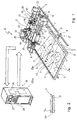
- Number 1 in Figure 1 indicates as a whole a machine for producing plane glass articles 2 having respective major surfaces 2a on which are formed, by material removal, lettering, designs, cavities and/or through holes indicated as a whole by D.
- Articles 2 are formed from an ordinary sheet 3 of glass or from sheets comprising at least one glass portion 3a and at least one layer 3b partially covering portion 3a and made of metal and/or plastic material and/or by depositing paint.
- machine 1 comprises a supporting frame 4; and a board 5 defining a supporting surface 6 for the sheet 3 of glass for processing, and which is connected to frame 4 either in a fixed position or on a swivel for easy loading of sheet 3.
- machine 1 also comprises a known powered cutting bridge 7 which in turn comprises two uprights 8, each connected in sliding manner to a respective straight guide 9 integral with board 5 so as to slide in a longitudinal direction 10, and a cross member 12 extending over supporting surface 6.
- a powered cutting carriage 14 is fitted to cross member 12 so as to slide in a direction 13 perpendicular to direction 10, and carries a supporting assembly 15 for supporting a known notching tool 16 not described in detail.
- Machine 1 also comprises a respective electronic control unit 18 for controlling the movement of bridge 7 and carriage 14 in their respective directions, and for moving notching tool 16 along given paths to form a number of notch lines 17, some of which are shown by way of example by the dash lines in Figure 1.
- machine 1 also comprises a tracing station 20 forming at least part of surface 6; and a known tracing device 21 which is movable at station 20, as described later on, to trace a reference path P1 located at station 20.
- reference path P1 is defined by the contour of a two- or three-dimensional pattern 22.
- Tracing device 21 is connected directly, by wiring (not shown), to unit 18 which comprises a memory 26 for memorizing in known manner the reference path P1 traced by device 21, and a control assembly - shown schematically and indicated 26a - for controlling and synchronizing bridge 7, carriage 14, and assembly 15.
- device 21 traces path P1 located at station 20, and supplies path P1 directly to unit 18, which memorizes path P1 in memory 26.
- unit 18, as a function of path P1 supplies signals to so control bridge 7 and carriage 14 as to move notching tool 16 along a notching path identical to the traced path.
- the traced path P1 may be altered by the operator by means of unit 18.
- unit 18 comprises a display device 27 for displaying the memorized path; and a keyboard 28 by which the machine 1 operator may, e.g. when setting and setting up machine 1, correct and/or alter the memorized traced path P1 to obtain and memorize another desired reference path.
- the operator instructs unit 18 to control notching tool 16 as a function of the newly memorized reference path.
- the operator may then select one of the paths in memory 26 and control the movement of notching tool 16 according to the selected path.
- machine 1 also comprises a known break-off assembly 29 by which sheet 3 is broken along the previously formed notch lines 17; and a further cutting bridge 30 which, in the example shown, is similar to bridge 7, is connected to board 5 in the same way as bridge 7, and carries a respective powered carriage 31 which slides in a direction parallel to direction 13.
- carriage 31 supports tracing device 21 and a known rotary toolhead 32.
- Toolhead 32 rotates about an axis substantially parallel to supporting surface 6, and comprises a number of selectively activated spindles 33 and 34, each fitted with a respective cutting tool 35, e.g. a grinding wheel, cutter and/or drill, for performing a material-removing operation on sheet 3; spindles 33 have respective axes of rotation parallel to surface 6, and spindle 34 a respective axis of rotation perpendicular to surface 6.
- Bridge 30, carriage 31 and toolhead 32 are also controlled by unit 18 which - again on the basis of paths traced beforehand by device 21 as described previously and memorized in unit 18, or on the basis of instructions entered directly by the operator from keyboard 28 - supplies bridge 30, carriage 31 and toolhead 32 with a number of control signals - independent of those supplied to bridge 7, carriage 14 and assembly 15 supporting notching tool 16 - to perform cutting, grinding and drilling operations on surface 2a of each article 2. More specifically, in actual use, once unit 18 is instructed directly or by means of tracing device 21, notch lines 17 are formed defining the various articles 2, after which, the desired additional operations are performed on surfaces 2a of articles 2 by toolhead 32 removing only glass material, in the case of straightforward glass sheets, and/or various other materials when working with partly surfaced sheets.
- break-off assembly 29 is activated, if sheet 3 is a straightforward glass sheet, and sheet 3 is broken to physically separate the various by now finished articles.
- the additional operations are performed on sheet 3 before sheet 3 is notched with lines 17.
- the additional operations may be performed, as stated, before or after breaking off portion 3a, but before cutting cover layer 3b, which holds the various articles together in practically fixed positions with respect to one another, even after glass portion 3a is broken off.
- the method described of producing processed glass articles therefore involves no transfer of the semifinished articles from the break-off station to a storage region and from the storage region to the various operating units, and no individual positioning of the semifinished articles on the operating units.
- the articles are not separated physically from one another until after the additional operations are completed, so that, throughout additional processing, the various articles are locked permanently to one another in given fixed positions.
- the method described therefore provides for considerably reducing cycle time, eliminating the need for specially designed fixtures, and so reducing production cost, while at the same time obtaining articles of consistent quality standard, regardless of the size of the articles.
- the tracing device and the notching tool together obviously permit the formation on sheet 3 of notch lines 17 of any shape, and in particular notch lines of particular shapes which cannot be keyboard-entered directly into unit 18, while the tracing device and the rotary toolhead together enable any material-removing operation to be performed on surfaces 2a of articles 2. That is, as for notching tool 16, spindles 33 and 34 may be operated to faithfully reproduce the pattern traced by device 21, or the traced pattern may be altered to obtain another desired pattern which, as stated, may also be memorized and used for controlling different cutting tools.
- the method described may obviously be implemented by machines other than machine 1 described by way of example, and in particular by a number of different machines through which the whole sheet 3 is transferred before being fed to a cutting/break-off assembly to physically separate the finished articles 2.
Landscapes
- Chemical & Material Sciences (AREA)
- Engineering & Computer Science (AREA)
- Materials Engineering (AREA)
- Organic Chemistry (AREA)
- Re-Forming, After-Treatment, Cutting And Transporting Of Glass Products (AREA)
- Glass Compositions (AREA)
Applications Claiming Priority (2)
| Application Number | Priority Date | Filing Date | Title |
|---|---|---|---|
| ITTO980712 | 1998-08-14 | ||
| IT1998TO000712A IT1303232B1 (it) | 1998-08-14 | 1998-08-14 | Metodo per la realizzazione di articoli di vetro a sviluppo piano. |
Publications (2)
| Publication Number | Publication Date |
|---|---|
| EP0980848A2 true EP0980848A2 (fr) | 2000-02-23 |
| EP0980848A3 EP0980848A3 (fr) | 2000-06-28 |
Family
ID=11416998
Family Applications (1)
| Application Number | Title | Priority Date | Filing Date |
|---|---|---|---|
| EP99115922A Withdrawn EP0980848A3 (fr) | 1998-08-14 | 1999-08-12 | Procédé de fabrication d'objets en verre plat |
Country Status (2)
| Country | Link |
|---|---|
| EP (1) | EP0980848A3 (fr) |
| IT (1) | IT1303232B1 (fr) |
Family Cites Families (6)
| Publication number | Priority date | Publication date | Assignee | Title |
|---|---|---|---|---|
| US2328405A (en) * | 1941-07-17 | 1943-08-31 | Libbey Owens Ford Glass Co | Cutting machine |
| US3150806A (en) * | 1962-04-10 | 1964-09-29 | Foster Grant Co Inc | Means and method for selectively breaking fragile members |
| DE2657757C2 (de) * | 1976-12-20 | 1984-08-02 | Bottero S.P.A., Cuneo-Spinetta | Vorrichtung zum Zuschneiden von Verbundglasplatten |
| DE3339320C2 (de) * | 1983-10-29 | 1986-10-16 | VEGLA Vereinigte Glaswerke GmbH, 5100 Aachen | Verfahren zur Herstellung einer Verbundglasscheibe |
| US4709483A (en) * | 1984-03-14 | 1987-12-01 | Wing Aero | Glass cutting device |
| GB2244231A (en) * | 1989-11-02 | 1991-11-27 | Hickman James A A | Cutting of cured resin based articles |
-
1998
- 1998-08-14 IT IT1998TO000712A patent/IT1303232B1/it active IP Right Grant
-
1999
- 1999-08-12 EP EP99115922A patent/EP0980848A3/fr not_active Withdrawn
Also Published As
| Publication number | Publication date |
|---|---|
| ITTO980712A1 (it) | 2000-02-14 |
| ITTO980712A0 (it) | 1998-08-14 |
| IT1303232B1 (it) | 2000-11-02 |
| EP0980848A3 (fr) | 2000-06-28 |
Similar Documents
| Publication | Publication Date | Title |
|---|---|---|
| US5407415A (en) | Automated composite trim workstation | |
| US6935003B2 (en) | Compound fabrication process and apparatus | |
| EP1310327B1 (fr) | Dispositif d'usinage de verre de lunettes | |
| US4995286A (en) | Apparatus for removing flash from molded products | |
| EP1175962B1 (fr) | Dispositif de production de verres optiques | |
| CN105105432A (zh) | 一种多轴数控首饰批花机及其实现方法 | |
| EP0484674B1 (fr) | Procédé pour l'usinage automatique des bords de plaques de verre et appareil pour exécuter le procédé | |
| CN204930588U (zh) | 一种多轴数控首饰批花机 | |
| US5482589A (en) | Method and apparatus for making pre-cut pre-preg tape | |
| KR100890644B1 (ko) | 브이컷 가공이 가능한 다목적 조각기 | |
| JP3078869B2 (ja) | 板材加工機 | |
| EP1247611B1 (fr) | Centre d'usinage à plusieurs axes, pour usinage multiple, en particulier pour le travail du bois | |
| KR100926342B1 (ko) | 경사 가공이 가능한 복합 가공기 | |
| JPH10507692A (ja) | Cncマシニングシステム | |
| JP5305733B2 (ja) | プリント基板分割装置及び方法 | |
| US5158422A (en) | Method and apparatus for shaping and finishing lenses | |
| EP0980847B1 (fr) | Table de coupe pour le traitement de feuilles de verre | |
| EP0980848A2 (fr) | Procédé de fabrication d'objets en verre plat | |
| JP4554842B2 (ja) | 軸状ワークの加工装置 | |
| CN113075908B (zh) | 数控雕铣加工宝玉石工艺品的方法 | |
| JP2002520177A (ja) | 2ステップサイクルで少なくとも2つの孔を穿孔するための方法 | |
| CN209698448U (zh) | 一种车雕双用的贵金属佛珠加工装置 | |
| JP3045535U (ja) | 加工装置および切断加工装置 | |
| JP4090748B2 (ja) | ワーク加工装置 | |
| KR102779487B1 (ko) | 대나무 가공 장치 |
Legal Events
| Date | Code | Title | Description |
|---|---|---|---|
| PUAI | Public reference made under article 153(3) epc to a published international application that has entered the european phase |
Free format text: ORIGINAL CODE: 0009012 |
|
| AK | Designated contracting states |
Kind code of ref document: A2 Designated state(s): AT BE CH CY DE DK ES FI FR GB GR IE IT LI LU MC NL PT SE |
|
| AX | Request for extension of the european patent |
Free format text: AL;LT;LV;MK;RO;SI |
|
| PUAL | Search report despatched |
Free format text: ORIGINAL CODE: 0009013 |
|
| AK | Designated contracting states |
Kind code of ref document: A3 Designated state(s): AT BE CH CY DE DK ES FI FR GB GR IE IT LI LU MC NL PT SE |
|
| AX | Request for extension of the european patent |
Free format text: AL;LT;LV;MK;RO;SI |
|
| 17P | Request for examination filed |
Effective date: 20001218 |
|
| AKX | Designation fees paid |
Free format text: AT BE CH CY DE DK ES FI FR GB GR IE IT LI LU MC NL PT SE |
|
| 17Q | First examination report despatched |
Effective date: 20020830 |
|
| STAA | Information on the status of an ep patent application or granted ep patent |
Free format text: STATUS: THE APPLICATION IS DEEMED TO BE WITHDRAWN |
|
| 18D | Application deemed to be withdrawn |
Effective date: 20030110 |