EP0980925A1 - Vorrichtung zum Eintragen von Schussfäden für eine Reihenfachwebmaschine und Reihenfachwebmaschine mit einer Vorrichtung - Google Patents
Vorrichtung zum Eintragen von Schussfäden für eine Reihenfachwebmaschine und Reihenfachwebmaschine mit einer Vorrichtung Download PDFInfo
- Publication number
- EP0980925A1 EP0980925A1 EP99810620A EP99810620A EP0980925A1 EP 0980925 A1 EP0980925 A1 EP 0980925A1 EP 99810620 A EP99810620 A EP 99810620A EP 99810620 A EP99810620 A EP 99810620A EP 0980925 A1 EP0980925 A1 EP 0980925A1
- Authority
- EP
- European Patent Office
- Prior art keywords
- channels
- channel
- unit
- component
- weft
- Prior art date
- Legal status (The legal status is an assumption and is not a legal conclusion. Google has not performed a legal analysis and makes no representation as to the accuracy of the status listed.)
- Withdrawn
Links
- 238000003780 insertion Methods 0.000 title claims abstract description 7
- 230000037431 insertion Effects 0.000 claims abstract description 6
- 238000009941 weaving Methods 0.000 claims description 17
- 238000000605 extraction Methods 0.000 abstract 2
- 238000005096 rolling process Methods 0.000 abstract 1
- 230000003068 static effect Effects 0.000 abstract 1
- 238000010304 firing Methods 0.000 description 3
- 230000001360 synchronised effect Effects 0.000 description 2
- 238000007789 sealing Methods 0.000 description 1
Images



Classifications
-
- D—TEXTILES; PAPER
- D03—WEAVING
- D03D—WOVEN FABRICS; METHODS OF WEAVING; LOOMS
- D03D41/00—Looms not otherwise provided for, e.g. for weaving chenille yarn; Details peculiar to these looms
- D03D41/005—Linear-shed multiphase looms
Definitions
- the invention relates to a device for inserting weft threads according to the preamble of claim 1 and one Row shed loom with one device.
- EP-A-0 433 216 there is a device for distributing the weft threads from a thread feeder to several weft channels
- Weaving rotors of a series shed weaving machine which have a fixed Part and a part rotating with the weaving rotor, which in one rotationally symmetrical surface a common separating and sealing surface own and via which the weft threads are transferred.
- the stationary part channels are formed in a known arrangement and Nozzles are provided for each channel to remove the weft threads from one of the Pull the weft supplying device and into the respective channel introduce.
- Takeover channels are in in the part rotating with the weaving rotor formed a known arrangement and provided shooting tubes, around the weft threads fed from the nozzles into the ones on the weaving rotor to shoot trained firing channels.
- Thread parts e.g. Fibrils in the gap between the fixed and the with can penetrate the rotating part of the weaving rotor. From this follows one Significant restriction of what is to be woven on the weaving machine Types of yarn.
- the invention is based on the object of a device of this type improve.
- weft threads are characterized by the features of claim 13 featured.
- the loom has the advantage of being discontinuous Feeding the weft is possible Weft yarn free and according to a predetermined program for the Select weft entry.
- FIG. 1 shows a weaving rotor 1 and a device 2 according to the invention for inserting weft threads 3 for a row shed weaving machine.
- the device 2 comprises a stationary unit 4 for feeding the weft threads, a unit 5 for feeding the weft threads, which are synchronized with the weaving rotor 1 about the axis of rotation 6 in the direction of arrow A. rotates and a rotary slide valve 7 for supplying the air.
- Unit 4 for Feeding the weft threads has a holder 8 for an arrangement 11 of Channels.
- the unit 5 for feeding the weft threads has twelve Injector nozzles 12, which are arranged on a cylindrical support part 13.
- the support member includes a first annular portion 14 for the Nozzle body and a second annular portion 15 for the Nozzle orifices. It should be noted that the nozzles are in one common section can be arranged and that the number of Nozzles may vary.
- the device contains the stationary arranged unit 4 for feeding the weft threads and a unit 5 for feeding the weft threads, which are synchronous with the weaving rotor 1 turns.
- the unit 4 for feeding the weft threads 3 contains a holder 21 and an assembly 22 mounted on the holder.
- Unit 5 for Feeding the weft threads 3 comprises a cylindrical support part 23 and twelve injector nozzles 12, their entry and exit on the same pitch circle 24 lie.
- the arrangement 22 comprises four units 25, the channels Form 26 and are arranged in a fan shape.
- a component 27 consists of a first section 28 with the units 25 and a second section 29 which is connected to the units and which has an opening 30.
- Each channel 26 has a nozzle 31 for feeding a weft thread assigned.
- Each channel 26 has one in the direction of the axis of rotation 6 continuously tapering cross-section, so that a gap 32 for Pulling out the weft thread is formed.
- the injector nozzles 12 are at equal intervals on a pitch circle 41 arranged horizontally such that the inlet of the injector nozzle and the Opening 30 of section 29 when taking over a weft thread 3 are aligned.
- the inlet is advantageously the Injector nozzle expanded in a funnel shape to take over the weft thread ensure.
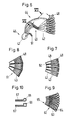
- FIG. 4 shows the component 27 according to FIG. 3 in a stretched representation.
- the stress on the weft thread while pulling it out of the To reduce channel 26 and the entry in the shed it can by It may be advantageous to vary the depth of the channel 26 as shown shape.
- FIGS. 6 and 7. show another embodiment of the arrangement with four units 42, each two Form channels 43 and are arranged in a fan shape.
- the arrangement is as Component 44 is formed and consists of a first section 45 with the Units 42 and a second section 46 which is associated with the units is connected and has an opening 47.
- Each channel 43 is a nozzle 48 assigned to feed a weft.
- the two channels 43 each Unit are separated by an intermediate wall 49 and form one common gap 50 to pull out a weft.
- an auxiliary nozzle 51 is provided, which in the second section 46 of the component 44 is arranged so that the mouth of the auxiliary nozzle on the opening 47th is aligned.
- FIG. 8 shows a unit 61 with four channels 43. It is on it note that the number of channels 43 may vary.
- FIG. 9 shows eight units 62, each of which forms a channel 63, wherein each channel from a transport channel 64 and a pull-out channel 65 consists.
- each channel from a transport channel 66 and a pull-out channel 67 shows cross-sectional shapes of designs of units, wherein each channel from a transport channel 66 and a pull-out channel 67 consists.
- FIG. 11 shows a device 71 for the continuous feeding of Weft threads 3 with a thread conveying device 72 for each nozzle 31.
- Figure 12 shows a device 81 for discontinuous, i.e. selective Supplying weft threads 3 with a thread store 82 for each nozzle 31, wherein the thread store is provided with a thread stop member 83.
- the device contains a stationary unit 4, the one Arrangement 22 having a plurality of channels 26 and a plurality of Has nozzles 31 for supplying weft threads 3 and one with the Webrotor 1 rotating unit 5 with a plurality of injector nozzles 12, the for this purpose, the weft threads fed to the channels are successively subtract and feed into the shed.
- This device ensures the insertion of weft threads different types and designs.
Landscapes
- Engineering & Computer Science (AREA)
- Textile Engineering (AREA)
- Looms (AREA)
Abstract
Description
- Fig.1
- Eine Seitenansicht einer Ausführung einer erfindungsgemässen Vorrichtung;
- Fig.2
- eine schematische Darstellung der ortsfesten und rotierenden Einheit gemäss Fig.1 zu Beginn der Schussfadeneintragung;
- Fig.3
- eine Ausführung eines Bauteiles mit einer erfindungsgemässen Kanalanordnung in räumlicher Darstellung;
- Fig.4
- das Bauteil gemäss Fig.3 in gestreckter Darstellung;
- Fig.6
- eine zweite Ausführung eines Bauteiles mit einer erfindungsgemässen Kanalanordnung in räumlicher Darstellung;
- Fig.7
- einen Schnitt entlang der Linie VII-VII in Fig.6;
- Fig.8
- einen Querschnitt einer anderen Ausführung einer Kanalanordnung;
- Fig.9
- einen Querschnitt einer weiteren Ausführung einer Kanalanordnung;
- Fig.10
- Querschnitte von Kanälen;
- Fig.11
- eine Ausführung einer Einrichtung zum kontinuierlichen Zuführen von Schussfäden und
- Fig.12
- eine Ausführung einer Einrichtung zum diskontinuierlichen Zuführen von Schussfäden.
Claims (13)
- Vorrichtung zum Eintragen von Schussfäden in eine Reihenfachwebmaschine mit einem Webrotor (1), der Schusseintragskanäle aufweist, welche Vorrichtung (2) eine ortsfest angeordnete Einheit (4) mit einer Mehrzahl von Kanälen (26,43) und mit einer Mehrzahl von Düsen (12) zum Eintragen der Schussfäden (3) und eine mit dem Webrotor rotierende Einheit (5) aufweist, um die Schussfäden in die Schusseintragskanäle einzuspeisen, dadurch gekennzeichnet, dass die Düsen (12) an der mit dem Webrotor (1) drehenden Einheit (5) vorgesehen sind, um die den Kanälen (26,43,63) zugeführten Schussfäden abzuziehen und in die Schusseintragskanäle einzutragen.
- Vorrichtung nach Anspruch 1, dadurch gekennzeichnet, dass eine Mehrzahl von zweiten Düsen (31,48) vorgesehen sind, die an der ortsfesten Einheit (4) angeordnet sind, um die Schussfäden (3) in die Kanäle zu fördern, wobei die Schussfäden einer Vorratseinrichtung (71,81) den zweiten Düsen entweder kontinuierlich oder diskontinuierlich zugeführt werden.
- Vorrichtung nach Anspruch 1 oder 2, dadurch gekennzeichnet, dass die ortsfeste Einheit einen Halter (21) und eine Anordnung (22) von Kanälen (26,43,63) aufweist, wobei die Kanäle bogenförmig ausgebildet und im Wesentlichen konzentrisch am Halter angeordnet sind.
- Vorrichtung nach einem der Ansprüche 1 bis 3, gekennzeichnet durch Einheiten (25,42), welche die Kanäle bilden und fächerförmig angeordnet sind.
- Vorrichtung nach einem der Ansprüche 1 bis 4, dadurch gekennzeichnet, dass der Kanal (63) einen Transportkanal (64,66) und einen Ausziehkanal (65,67) umfasst.
- Vorrichtung nach Anspruch 5, dadurch gekennzeichnet, dass der Transportkanal (64,66) eine lichte Weite hat, die grösser ist, als die lichte Weite des Ausziehkanals (65,67).
- Vorrichtung nach einem der Ansprüche 1 bis 6, dadurch gekennzeichnet, dass die Kanäle (26,43,63) in einem Bauteil (27,44) zusammengefasst sind, wobei jeder Kanal mindestens einen Einlass hat und wobei alle Kanäle in einen gemeinsamen Auslass münden.
- Vorrichtung nach einem der Ansprüche 1 bis 7, dadurch gekennzeichnet, dass der Bauteil (27,44) eine Anzahl von Einheiten (25,42) enthält und dass der Bauteil aus einem ersten Abschnitt (28,45) mit den Kanälen und einem zweiten Abschnitt (29,46) besteht, in welchen die Kanäle münden und der eine Öffnung (30,47) aufweist.
- Vorrichtung nach einem der Ansprüche 1 bis 8, dadurch gekennzeichnet, dass die Kanäle (25,43) in Gruppen unterteilt sind und dass der Bauteil (27,44) mindestens eine Gruppe von Kanälen aufweist.
- Vorrichtung nach einem der Ansprüche 1 bis 9, dadurch gekennzeichnet, dass der Kanal (26,43) einen Querschnitt aufweist, der sich zur offenen Längsseite hin verjüngt.
- Vorrichtung nach einem der Ansprüche 1 bis 10 gekennzeichnet durch eine Hilfsdüse (51), die in den zweiten Abschnitt (29,46)des Bauteiles so angeordnet ist, dass die Mündung der Hilfsdüse auf die Öffnung (30,47) gerichtet ist.
- Vorrichtung nach einem der Ansprüche 1 bis 4, dadurch gekennzeichnet, dass die Düsen (12) in gleichen Winkelabständen auf einem gemeinsamen Teilkreis (24) angeordnet sind.
- Reihenfachwebmaschine mit einer Vorrichtung nach einem der Ansprüche 1 bis 12.
Priority Applications (1)
| Application Number | Priority Date | Filing Date | Title |
|---|---|---|---|
| EP99810620A EP0980925A1 (de) | 1998-08-19 | 1999-07-12 | Vorrichtung zum Eintragen von Schussfäden für eine Reihenfachwebmaschine und Reihenfachwebmaschine mit einer Vorrichtung |
Applications Claiming Priority (3)
| Application Number | Priority Date | Filing Date | Title |
|---|---|---|---|
| EP98810807A EP0980923A1 (de) | 1998-08-19 | 1998-08-19 | Vorrichtung zum Eintragen von Schussfäden für eine Reihenfachwebmaschine und Reihenfachwebmaschine mit einer Vorrichtung |
| EP98810807 | 1998-08-19 | ||
| EP99810620A EP0980925A1 (de) | 1998-08-19 | 1999-07-12 | Vorrichtung zum Eintragen von Schussfäden für eine Reihenfachwebmaschine und Reihenfachwebmaschine mit einer Vorrichtung |
Publications (1)
| Publication Number | Publication Date |
|---|---|
| EP0980925A1 true EP0980925A1 (de) | 2000-02-23 |
Family
ID=26151994
Family Applications (1)
| Application Number | Title | Priority Date | Filing Date |
|---|---|---|---|
| EP99810620A Withdrawn EP0980925A1 (de) | 1998-08-19 | 1999-07-12 | Vorrichtung zum Eintragen von Schussfäden für eine Reihenfachwebmaschine und Reihenfachwebmaschine mit einer Vorrichtung |
Country Status (1)
| Country | Link |
|---|---|
| EP (1) | EP0980925A1 (de) |
Citations (3)
| Publication number | Priority date | Publication date | Assignee | Title |
|---|---|---|---|---|
| EP0143860A1 (de) * | 1983-12-01 | 1985-06-12 | Maschinenfabrik Sulzer-Rüti Ag | Schussfadenaufbereitungsvorrichtung für Reihenfachwebmaschinen |
| EP0433216A1 (de) | 1989-11-16 | 1991-06-19 | Sulzer RàTi Ag | Schussfadenverteilvorrichtung einer Reihenfachwebmaschine mit Lufteintrag |
| EP0685584A1 (de) * | 1994-05-30 | 1995-12-06 | Sulzer RàTi Ag | Verfahren und Vorrichtung zum Eintrag von Schussfäden in eine Reihenfachwebmaschine |
-
1999
- 1999-07-12 EP EP99810620A patent/EP0980925A1/de not_active Withdrawn
Patent Citations (3)
| Publication number | Priority date | Publication date | Assignee | Title |
|---|---|---|---|---|
| EP0143860A1 (de) * | 1983-12-01 | 1985-06-12 | Maschinenfabrik Sulzer-Rüti Ag | Schussfadenaufbereitungsvorrichtung für Reihenfachwebmaschinen |
| EP0433216A1 (de) | 1989-11-16 | 1991-06-19 | Sulzer RàTi Ag | Schussfadenverteilvorrichtung einer Reihenfachwebmaschine mit Lufteintrag |
| EP0685584A1 (de) * | 1994-05-30 | 1995-12-06 | Sulzer RàTi Ag | Verfahren und Vorrichtung zum Eintrag von Schussfäden in eine Reihenfachwebmaschine |
Similar Documents
| Publication | Publication Date | Title |
|---|---|---|
| EP0433216B1 (de) | Schussfadenverteilvorrichtung einer Reihenfachwebmaschine mit Lufteintrag | |
| DE2620118A1 (de) | Garnspinnmaschine | |
| CH622563A5 (de) | ||
| EP2230341A1 (de) | Verfahren und Speichervorrichtung zum Speichern von Schussfäden in einer Webmaschine | |
| EP0039009B1 (de) | Verfahren und Vorrichtung zum pneumatischen Eintragen des Schussfadens in die Schussfadenträger einer mehrsystemigen Webmaschine | |
| EP1630269B1 (de) | Fadenführer | |
| EP0980923A1 (de) | Vorrichtung zum Eintragen von Schussfäden für eine Reihenfachwebmaschine und Reihenfachwebmaschine mit einer Vorrichtung | |
| EP0582763A1 (de) | Vorrichtung zum Halten von Schussfäden für Reihenfachwebmaschinen | |
| EP1092053A1 (de) | Vorrichtung und verfahren zum abteilen von fäden aus einer schicht | |
| EP0949370B1 (de) | Schlussfadeneintragsvorrichtung für eine Luftdüsenwebmaschine | |
| EP1006223A1 (de) | Vorrichtung zum Auflösen von Faserbändern | |
| CH610366A5 (en) | Device for inserting weft threads into a shed | |
| DE3220064C2 (de) | ||
| EP0980924A1 (de) | Vorrichtung zum Eintragen von Schussfäden für eine Reihenfachwebmaschine und Reihenfachwebmaschine mit einer Vorrichtung | |
| EP0143859B1 (de) | Webrotor für pneumatische Reihenfachwebmaschinen | |
| EP0828880B1 (de) | Fadenhaltevorrichtung mit sich überlappenden halteelementen und mit einführelementen | |
| EP0127719A1 (de) | Vorrichtung zum Abziehen von abgetrennten Gewebeteilen auf einer Webmaschine | |
| EP0236324B1 (de) | Offenend-spinnverfahren und vorrichtung zu seiner durchführung | |
| DE3521756C2 (de) | ||
| DE3025541C2 (de) | Mit Luft betriebene Saugdüse zum Erfassen von Fadenenden an Webmaschinen | |
| DE3008622C2 (de) | ||
| DE60122799T2 (de) | Verfahren und Vorrichtung zur Herstellung von Einlegekanten auf Luftdüsenwebmaschinen | |
| DE102023125211B3 (de) | Schusseintragsvorrichtung für eine Webmaschine | |
| DE102022200452B3 (de) | Schusseintragsvorrichtung für eine luftdüsenwebmaschine, düsenaufsatz sowie luftdüsenwebmaschine | |
| EP0022812A1 (de) | Einrichtung zur schussfadenvorbereitung an einer webmaschine mit schützenloser schusseintragung |
Legal Events
| Date | Code | Title | Description |
|---|---|---|---|
| PUAI | Public reference made under article 153(3) epc to a published international application that has entered the european phase |
Free format text: ORIGINAL CODE: 0009012 |
|
| AK | Designated contracting states |
Kind code of ref document: A1 Designated state(s): BE DE IT |
|
| AX | Request for extension of the european patent |
Free format text: AL;LT;LV;MK;RO;SI |
|
| RAP1 | Party data changed (applicant data changed or rights of an application transferred) |
Owner name: SULZER TEXTIL AG |
|
| RAP1 | Party data changed (applicant data changed or rights of an application transferred) |
Owner name: SULZER TEXTIL AG |
|
| 17P | Request for examination filed |
Effective date: 20000727 |
|
| AKX | Designation fees paid |
Free format text: BE DE IT |
|
| GRAH | Despatch of communication of intention to grant a patent |
Free format text: ORIGINAL CODE: EPIDOS IGRA |
|
| STAA | Information on the status of an ep patent application or granted ep patent |
Free format text: STATUS: THE APPLICATION IS DEEMED TO BE WITHDRAWN |
|
| 18D | Application deemed to be withdrawn |
Effective date: 20030617 |