EP0980966A1 - Abgasanlage einer Brennkraftmaschine mit einem Speichervolumen - Google Patents
Abgasanlage einer Brennkraftmaschine mit einem Speichervolumen Download PDFInfo
- Publication number
- EP0980966A1 EP0980966A1 EP99115344A EP99115344A EP0980966A1 EP 0980966 A1 EP0980966 A1 EP 0980966A1 EP 99115344 A EP99115344 A EP 99115344A EP 99115344 A EP99115344 A EP 99115344A EP 0980966 A1 EP0980966 A1 EP 0980966A1
- Authority
- EP
- European Patent Office
- Prior art keywords
- internal combustion
- combustion engine
- exhaust gas
- storage volume
- exhaust
- Prior art date
- Legal status (The legal status is an assumption and is not a legal conclusion. Google has not performed a legal analysis and makes no representation as to the accuracy of the status listed.)
- Granted
Links
Images
Classifications
-
- F—MECHANICAL ENGINEERING; LIGHTING; HEATING; WEAPONS; BLASTING
- F02—COMBUSTION ENGINES; HOT-GAS OR COMBUSTION-PRODUCT ENGINE PLANTS
- F02D—CONTROLLING COMBUSTION ENGINES
- F02D9/00—Controlling engines by throttling air or fuel-and-air induction conduits or exhaust conduits
- F02D9/04—Controlling engines by throttling air or fuel-and-air induction conduits or exhaust conduits concerning exhaust conduits
-
- F—MECHANICAL ENGINEERING; LIGHTING; HEATING; WEAPONS; BLASTING
- F01—MACHINES OR ENGINES IN GENERAL; ENGINE PLANTS IN GENERAL; STEAM ENGINES
- F01N—GAS-FLOW SILENCERS OR EXHAUST APPARATUS FOR MACHINES OR ENGINES IN GENERAL; GAS-FLOW SILENCERS OR EXHAUST APPARATUS FOR INTERNAL-COMBUSTION ENGINES
- F01N3/00—Exhaust or silencing apparatus having means for purifying, rendering innocuous, or otherwise treating exhaust
- F01N3/08—Exhaust or silencing apparatus having means for purifying, rendering innocuous, or otherwise treating exhaust for rendering innocuous
- F01N3/10—Exhaust or silencing apparatus having means for purifying, rendering innocuous, or otherwise treating exhaust for rendering innocuous by thermal or catalytic conversion of noxious components of exhaust
- F01N3/18—Exhaust or silencing apparatus having means for purifying, rendering innocuous, or otherwise treating exhaust for rendering innocuous by thermal or catalytic conversion of noxious components of exhaust characterised by methods of operation; Control
-
- F—MECHANICAL ENGINEERING; LIGHTING; HEATING; WEAPONS; BLASTING
- F01—MACHINES OR ENGINES IN GENERAL; ENGINE PLANTS IN GENERAL; STEAM ENGINES
- F01N—GAS-FLOW SILENCERS OR EXHAUST APPARATUS FOR MACHINES OR ENGINES IN GENERAL; GAS-FLOW SILENCERS OR EXHAUST APPARATUS FOR INTERNAL-COMBUSTION ENGINES
- F01N3/00—Exhaust or silencing apparatus having means for purifying, rendering innocuous, or otherwise treating exhaust
- F01N3/08—Exhaust or silencing apparatus having means for purifying, rendering innocuous, or otherwise treating exhaust for rendering innocuous
- F01N3/10—Exhaust or silencing apparatus having means for purifying, rendering innocuous, or otherwise treating exhaust for rendering innocuous by thermal or catalytic conversion of noxious components of exhaust
- F01N3/18—Exhaust or silencing apparatus having means for purifying, rendering innocuous, or otherwise treating exhaust for rendering innocuous by thermal or catalytic conversion of noxious components of exhaust characterised by methods of operation; Control
- F01N3/20—Exhaust or silencing apparatus having means for purifying, rendering innocuous, or otherwise treating exhaust for rendering innocuous by thermal or catalytic conversion of noxious components of exhaust characterised by methods of operation; Control specially adapted for catalytic conversion
-
- F—MECHANICAL ENGINEERING; LIGHTING; HEATING; WEAPONS; BLASTING
- F02—COMBUSTION ENGINES; HOT-GAS OR COMBUSTION-PRODUCT ENGINE PLANTS
- F02M—SUPPLYING COMBUSTION ENGINES IN GENERAL WITH COMBUSTIBLE MIXTURES OR CONSTITUENTS THEREOF
- F02M26/00—Engine-pertinent apparatus for adding exhaust gases to combustion-air, main fuel or fuel-air mixture, e.g. by exhaust gas recirculation [EGR] systems
- F02M26/13—Arrangement or layout of EGR passages, e.g. in relation to specific engine parts or for incorporation of accessories
- F02M26/14—Arrangement or layout of EGR passages, e.g. in relation to specific engine parts or for incorporation of accessories in relation to the exhaust system
- F02M26/15—Arrangement or layout of EGR passages, e.g. in relation to specific engine parts or for incorporation of accessories in relation to the exhaust system in relation to engine exhaust purifying apparatus
-
- F—MECHANICAL ENGINEERING; LIGHTING; HEATING; WEAPONS; BLASTING
- F02—COMBUSTION ENGINES; HOT-GAS OR COMBUSTION-PRODUCT ENGINE PLANTS
- F02M—SUPPLYING COMBUSTION ENGINES IN GENERAL WITH COMBUSTIBLE MIXTURES OR CONSTITUENTS THEREOF
- F02M26/00—Engine-pertinent apparatus for adding exhaust gases to combustion-air, main fuel or fuel-air mixture, e.g. by exhaust gas recirculation [EGR] systems
- F02M26/13—Arrangement or layout of EGR passages, e.g. in relation to specific engine parts or for incorporation of accessories
- F02M26/34—Arrangement or layout of EGR passages, e.g. in relation to specific engine parts or for incorporation of accessories with compressors, turbines or the like in the recirculation passage
-
- F—MECHANICAL ENGINEERING; LIGHTING; HEATING; WEAPONS; BLASTING
- F02—COMBUSTION ENGINES; HOT-GAS OR COMBUSTION-PRODUCT ENGINE PLANTS
- F02M—SUPPLYING COMBUSTION ENGINES IN GENERAL WITH COMBUSTIBLE MIXTURES OR CONSTITUENTS THEREOF
- F02M26/00—Engine-pertinent apparatus for adding exhaust gases to combustion-air, main fuel or fuel-air mixture, e.g. by exhaust gas recirculation [EGR] systems
- F02M26/13—Arrangement or layout of EGR passages, e.g. in relation to specific engine parts or for incorporation of accessories
- F02M26/37—Arrangement or layout of EGR passages, e.g. in relation to specific engine parts or for incorporation of accessories with temporary storage of recirculated exhaust gas
-
- F—MECHANICAL ENGINEERING; LIGHTING; HEATING; WEAPONS; BLASTING
- F02—COMBUSTION ENGINES; HOT-GAS OR COMBUSTION-PRODUCT ENGINE PLANTS
- F02M—SUPPLYING COMBUSTION ENGINES IN GENERAL WITH COMBUSTIBLE MIXTURES OR CONSTITUENTS THEREOF
- F02M26/00—Engine-pertinent apparatus for adding exhaust gases to combustion-air, main fuel or fuel-air mixture, e.g. by exhaust gas recirculation [EGR] systems
- F02M26/65—Constructional details of EGR valves
- F02M26/71—Multi-way valves
-
- F—MECHANICAL ENGINEERING; LIGHTING; HEATING; WEAPONS; BLASTING
- F01—MACHINES OR ENGINES IN GENERAL; ENGINE PLANTS IN GENERAL; STEAM ENGINES
- F01N—GAS-FLOW SILENCERS OR EXHAUST APPARATUS FOR MACHINES OR ENGINES IN GENERAL; GAS-FLOW SILENCERS OR EXHAUST APPARATUS FOR INTERNAL-COMBUSTION ENGINES
- F01N2240/00—Combination or association of two or more different exhaust treating devices, or of at least one such device with an auxiliary device, not covered by indexing codes F01N2230/00 or F01N2250/00, one of the devices being
- F01N2240/26—Combination or association of two or more different exhaust treating devices, or of at least one such device with an auxiliary device, not covered by indexing codes F01N2230/00 or F01N2250/00, one of the devices being an exhaust gas reservoir, e.g. emission buffer
-
- F—MECHANICAL ENGINEERING; LIGHTING; HEATING; WEAPONS; BLASTING
- F02—COMBUSTION ENGINES; HOT-GAS OR COMBUSTION-PRODUCT ENGINE PLANTS
- F02M—SUPPLYING COMBUSTION ENGINES IN GENERAL WITH COMBUSTIBLE MIXTURES OR CONSTITUENTS THEREOF
- F02M26/00—Engine-pertinent apparatus for adding exhaust gases to combustion-air, main fuel or fuel-air mixture, e.g. by exhaust gas recirculation [EGR] systems
- F02M26/13—Arrangement or layout of EGR passages, e.g. in relation to specific engine parts or for incorporation of accessories
- F02M26/42—Arrangement or layout of EGR passages, e.g. in relation to specific engine parts or for incorporation of accessories having two or more EGR passages; EGR systems specially adapted for engines having two or more cylinders
Definitions
- the invention relates to an exhaust system of an internal combustion engine with a Exhaust gas cleaning device and with an evacuable storage volume, in particular after a start of the internal combustion engine for a certain period of time at least part of the internal combustion engine exhaust gas flow can be initiated.
- a Exhaust gas cleaning device and with an evacuable storage volume, in particular after a start of the internal combustion engine for a certain period of time at least part of the internal combustion engine exhaust gas flow can be initiated.
- DE 43 42 296 C1 or DE 40 25 565 A1 in particular to the GB 1 349 051.
- the exhaust gases of a motor vehicle internal combustion engine have to be cleaned, ie at least partially freed from harmful components, for which exhaust gas catalysts are used in particular.
- these catalytic converters require a certain operating temperature so that they can perform their function of converting harmful exhaust gas components.
- Modern so-called catalytic converters reach this so-called light-off temperature directly after a (cold) start of the internal combustion engine in conventional exhaust-gas test cycles only after about 25 seconds, so that during this period, which is also referred to below critical "period of time is referred to, that the internal combustion engine exhaust gas enters the environment virtually unpurified.
- a vacuum pump for generating the storage vacuum.
- a vacuum can generally be generated in the storage volume and held by means of the shut-off valve, so that the internal combustion engine exhaust gas is conveyed safely and efficiently into the storage volume during this critical time period by means of this vacuum.
- a vacuum pump of this type can be used in a safe manner to generate the vacuum required in the storage volume even before the internal combustion engine is started, even if the internal combustion engine has to be started repeatedly or after relatively long downtimes.
- a control valve for metered filling of the storage volume can be provided in a branch line leading the internal combustion engine exhaust gas flow to the storage volume, so that after starting the internal combustion engine with the desired filling of the storage volume associated therewith, the negative pressure initially present therein is not abruptly reduced, but quasi-metered .
- a control unit which suitably controls the vacuum pump and / or the control valve on the basis of the pressure sensor signals is provided in addition to a pressure sensor which detects the pressure value in the storage volume.
- a suitable adsorber material can be stored in the storage volume an undesirable exhaust gas component may be provided, so that in the Storage volume introduced exhaust gases at least partially cleaned at the same time before they expire after the desired or required storage period back into the exhaust pipe of the internal combustion engine be delivered.
- the exhaust system partially double-walled, so that two essentially Exhaust gas lines running coaxially to one another are present Via the first, preferably inner exhaust pipe, the exhaust gas from the internal combustion engine led away and via the second, preferably outer exhaust pipe is led to the storage volume.
- an exhaust system according to the invention is that the regionally double-walled exhaust system itself forms part of the storage volume, with a minimal additional space requirement, so that the actual storage volume can be made correspondingly smaller.
- a relatively simple exhaust gas routing to the storage volume arranged near the internal combustion engine is advantageously possible .
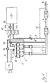
- Reference number 1 thus designates an (here four-cylinder reciprocating piston) internal combustion engine, the exhaust gases of which are first passed via exhaust manifolds 2 into (here two parallel side by side) electrically heated pre-catalysts 3.
- exhaust pipes 4 referred to as first exhaust pipe in FIG. 2
- exhaust pipes 4 ′ FIG. 1
- the internal combustion engine exhaust gases then enter a main catalytic converter 5 and from there through an exhaust pipe 4, which has at least one silencer 19, finally into the Surroundings.
- a shutoff flap 6 is provided in the exhaust line 4 downstream of the sound damper 19, by means of which the exhaust line 4 can be shut off essentially completely, ie when the shutoff flap 6 is closed, the exhaust gas flow flowing through the muffler 19 cannot get into the environment.
- the exhaust gas flow conducted in the exhaust gas line 4 ′ is conducted via a branch line 7 branching off upstream of the main catalytic converter 5 into a storage volume 8.
- the exhaust gas flow with the shut-off flap 6 closed can also be taken downstream of the main catalytic converter 5 or - as shown here via the branch line 7 ′ shown in dashed lines - downstream of the silencer 19 from the exhaust line 4 and fed to the storage volume 8.
- both a control valve 9 provided in the branch line 7 and a further shut-off valve 10a designed as a three-way valve 10 must be suitably connected for this purpose, ie these two valves 9, 10a, the function of which will be discussed in more detail later, must flow through the exhaust gas release the branch line 7 at least partially.
- the introduction of the exhaust gas flow into the storage volume 8 just described is intended to be harmful, particularly after a (cold) start of the internal combustion engine 1, if the pre-catalysts 3 and the main catalyst 5 have not yet reached their light-off temperature and are therefore not able Convert exhaust gas components (especially hydrocarbons) for a certain period of time (for example. 25 seconds).
- the shut-off flap 6 is opened so that the exhaust gas stream is then cleaned, ie freed from at least the essential pollutant components, and discharged into the environment.
- the storage volume 8 can be emptied in order to be able to start (cold) the internal combustion engine 1 again at a later (renewed) start, or the exhaust gas flow expelled during the aforementioned period of, for example, 25 seconds to record.
- This necessary emptying of the storage volume 8 can take place either into the intake system 11 of the internal combustion engine 1 or into the exhaust gas line 4 '.
- a drain line 17 branching off from the storage volume 8 is provided for this purpose, which branches in a branch valve 20 into a first line branch 17 ′ opening into the suction system 11 and into a second line branch 17 ′′ opening into the exhaust line 4 ′.
- the amount of exhaust gas initially stored in the storage volume 8 thus becomes either Cleaning "(or aftertreatment) through the then functional main catalytic converter 5, or alternatively introduced into the intake system 11 of the internal combustion engine 1.
- the amount of exhaust gas previously stored in the storage volume 8 is thus suitably dosed when the storage volume 8 is emptied for further post-combustion Internal combustion engine combustion chambers added to the fresh gas flow supplied for combustion, preferably in those operating points of the internal combustion engine 1 in which this addition is not a hindrance to the smooth running of the internal combustion engine 1.
- FIG. 1 the further elements shown in FIG. 1 in the periphery of the internal combustion engine 1 are briefly explained:
- the (here four) combustion chambers of the internal combustion engine 1 are supplied with fresh gas via the suction system 11 already mentioned.
- a throttle valve 13 is provided in an intake line 12 leading to the intake system 11 for controlling the power of the internal combustion engine 1.
- a conventional intake air filter 14 At the free end of the intake line 12 there is a conventional intake air filter 14.
- a secondary air line 15 which opens into the exhaust manifold 2 and is known to the person skilled in the art, branches off, in which, as usual, a secondary air pump 16 is provided, but for the present invention is immaterial.
- a vacuum pump 18 can be seen in this in addition to a shut-off valve 10b, which in turn is part of the three-way valve 10 already mentioned or forms this three-way valve 10 together with the other already mentioned shut-off valve 10a . If the shut-off valve 10a is now closed and the shut-off valve 10b is open, i.e. if the three-way valve 10 assumes the switch position shown in FIG. 1 , the storage volume 8 is sucked empty and thus evacuated when this vacuum pump 18 is operated at the same time, since this vacuum pump 18 has its suction side against the Storage volume 8 is connected. As already mentioned, the vacuum pump 18 then conveys the amount of exhaust gas located in the storage volume 8 via the emptying line 17 either into the suction system 11 or into the exhaust line 4 '.
- a feed pump (already shown in the aforementioned prior art) can also be provided which stores the amount of exhaust gas generated in the storage volume 8 below Overpressure enables this storage volume 8 to be dimensioned smaller.
- a feed pump of this type is shown in the usual way in FIG. 2 , which will be explained later, under the reference number 24.
- a lower-performing feed pump (24 ) can be used or - as in DE 43 42 296 C1, which has also already been mentioned, internal combustion engine 1 can be used to compress the exhaust gas by adapting its valve timing, after having initially (ie when starting the internal combustion engine ft machine 1) vacuum prevailing in the storage volume 8 ensures an absolutely safe introduction of the exhaust gas flow into the storage volume 8.
- control valve 9 For the described filling of the storage volume 8 by means of the vacuum originally prevailing therein, previously generated by the vacuum pump 18 and held by the shut-off valves 10a, 10b, the control valve 9 already briefly mentioned, which is arranged in the branch line 7, can now be particularly advantageous: In order to prevent the vacuum in the storage volume 8 from being abruptly reduced when the shut-off valve 10a is opened, this control valve 9 can be suitably controlled to form a throttle point which is only a gradual one, over a longer period of time, ie in particular over the period of time mentioned, for example. 25 seconds during the vacuum reduction in the storage volume 8 enables.
- an electronic control unit in particular, which, among other things, positions the shut-off flap 6 and the three-way valve 10, ie the shut-off valves 10a and 10b, according to the respective requirements.
- This control unit can also take over the suitable control of the control valve 9 and the vacuum pump 18, preferably using the signals of a pressure sensor provided in particular in the storage volume 8 and detecting the respective current pressure value therein.
- this control unit When filling the storage volume 8 during the critical "period of time, this control unit (possibly using other signals or boundary conditions) can suitably control the control valve 9 in the mouth area of the branch line 7 or 7" into the exhaust line 4 'or 4, an approximately constant negative pressure of, for example, 0.75 bar
- this control unit can ensure that this emptying and the associated admixture of the amount of exhaust gas collected in the storage volume 8 to the fresh gas flow supplied to the internal combustion engine combustion chambers only takes place in those operating points of the internal combustion engine 1 in which this addition is carried out for one perfect running of the internal combustion engine is not a hindrance.
- control unit operates the vacuum pump Monitor 18 such that the desired negative pressure in the storage volume 8 is generated in the desired order.
- the control unit operates the vacuum pump Monitor 18 such that the desired negative pressure in the storage volume 8 is generated in the desired order.
- the vacuum in the storage volume 8 it is also possible to set the vacuum in the storage volume 8 to be continuously monitored and also when the internal combustion engine is at a standstill 1 to ensure by temporarily operating the vacuum pump 18, that in the storage volume 8 always for a restart of the internal combustion engine 1 desired (or in view of the reduction that can be achieved with this of the exhaust gas emissions) is present.
- the conveying side should be connected to the environment are, for example, via the drain line 17 '' and the exhaust line 4.
- the delivery side of the vacuum pump 18 with the suction system 11 Internal combustion engine 1 is connectable, requires a reduced pump output if, in addition - as is known to the person skilled in the art - in the Suction system 11 at a variety of engine operating points (and particularly intensively at idle) prevailing negative pressure becomes.
- the control unit already mentioned can be the vacuum pump 18 operate appropriately.
- the detailed structure of the storage volume 8 is not to be discussed in detail. In essence, this can be a suitable vacuum storage that is stable when the evacuation is complete.
- an absolute tightness is required not only of the vacuum accumulator or the accumulator volume 8, but also of the check valves 10a, 10b (or the three-way valve 10) as well as the drain line 17 and the branch line 7.
- an adsorber material can also be provided in the storage volume 8, which itself stores at least one undesired exhaust gas component for a certain period of time or, as known to the person skilled in the art, for example, as activated carbon, has an adsorbent effect on pollutants.
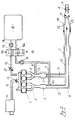
- FIG. 2 and the essential differences of this second exemplary embodiment compared to that according to FIG. 1 are now described: While in normal continuous engine operation the internal combustion engine exhaust gases ultimately reach the environment through the so-called first exhaust pipe 4, as shown by the flow arrow, via the main catalytic converter 5 and via the muffler 19, the internal combustion engine will also start during this 1 subsequent critical "time period during which neither the pre-catalysts 3 nor the main catalyst 5 have reached their starting or operating temperature, the shutoff valve 6 provided downstream of the muffler 19 in the exhaust line 4 is closed, so that the first exhaust line 4 essentially at this point When the shut-off flap 6 is closed, the exhaust gas flow flowing through the muffler 19 cannot get into the environment, but is directed into a storage volume 8.
- a transition 21 is provided in the first exhaust line 4 into a second exhaust line 22, into which the exhaust gas flow - as shown by flow arrows - enters with the shut-off valve 6 closed.
- This second exhaust line 22 is arranged coaxially or concentrically to the first exhaust line 4 or envelops the first exhaust line 4, an annular space (not specified in more detail) being present between the outer wall of the first exhaust line 4 and the inner wall of the second exhaust line 22, through which the internal combustion engine exhaust gases then be guided in the second exhaust line 22.
- This second exhaust line 22 extends from the transfer line 21 in the direction of the internal combustion engine 1 (back) to a so-called diversion 23, which is upstream of the pre-catalytic converter 3 here on the left-hand side with respect to the flow direction in the second exhaust-gas line 22, and for the pre-catalytic converter here on the right-hand side 3 is provided between this pre-catalyst 3 and the internal combustion engine 1.
- the internal combustion engine exhaust system shown is thus double-walled, with not only the exhaust line 4 but also the exhaust gas purification devices in the form of the main catalytic converter 5 and the pre-catalytic converter 3 on the right being encased by the exhaust gas line 22.
- the shut-off flap 6 When the shut-off flap 6 is closed, the internal combustion engine exhaust gases are thus introduced into the storage volume 8 via the second exhaust line 22 and the adjoining branch line 7.
- the check valve 10a provided in the branch line 7 and designed as a three-way valve 10 must also be suitably connected, ie this check valve 10a must release the flow of the exhaust gas flow through the branch line 7.
- the introduction of the exhaust gas flow into the storage volume 8 just described is intended to be harmful, particularly after a (cold) start of the internal combustion engine 1, if the pre-catalysts 3 and the main catalyst 5 have not yet reached their light-off temperature and are therefore not able Convert exhaust gas components (especially hydrocarbons) for a certain period of time (for example. 25 seconds).
- the shut-off flap 6 is opened so that the exhaust gas stream is then cleaned, ie freed from at least the essential pollutant components, and discharged into the environment.
- the storage volume can 8 to be emptied for a later (new) start or cold start the internal combustion engine 1 to be able to again during the said Time span of, for example, 25 seconds of exhaust gas flow to record.
- This required emptying of the storage volume 8 takes place in this second exemplary embodiment, only in the suction system 11 the internal combustion engine 1, namely via the drain line 17, wherein a targeted quantity control of those taken from the storage volume 8 and the suction system 11 fed and thus recirculated exhaust gas amount by means of a control valve provided in the drain line 17 25 takes place.
- the vacuum pump 18 In the emptying line 17 there is also the vacuum pump 18 already explained in connection with the exemplary embodiment according to FIG. 1.
- the pre-catalysts 3 generally an exhaust gas cleaning device
- the amount of exhaust gas previously collected in the storage volume 8 was removed from the storage volume 8 - an essentially absolute vacuum was created with this vacuum pump 18 in the storage volume 8.
- the exhaust gas stream is hereby simultaneously cooled, as a result of which the volume of the amount of exhaust gas to be stored (according to the physical equation of state for gases) is reduced, so that a larger amount of exhaust gas, ie exhaust gas mass, can thus be stored in a storage volume 8 predetermined in terms of its volume.
- the exhaust system is partially double-walled is, so that the engine exhaust gas in this area in one first exhaust pipe 4, which contains the exhaust gas purification device (s), led away from the internal combustion engine 1 and coaxially in a second this first extending exhaust pipe 22 in the manner of a counterflow heat exchanger returned in the direction of the internal combustion engine 1, ultimately, however, is introduced into the storage volume 8.
- the first exhaust pipe 4 is the inner one and the second one Exhaust line 22 around the outer exhaust line of the double-walled, an exhaust system having an annular space. Rather can also the first exhaust line 4 on the outside and the second exhaust line 22 be provided on the inside, the latter then the exhaust gas purification devices, i.e. the main catalytic converter 5 and the precatalyst (s) 3 would penetrate.
Landscapes
- Engineering & Computer Science (AREA)
- Chemical & Material Sciences (AREA)
- Combustion & Propulsion (AREA)
- Mechanical Engineering (AREA)
- General Engineering & Computer Science (AREA)
- Chemical Kinetics & Catalysis (AREA)
- Health & Medical Sciences (AREA)
- Toxicology (AREA)
- Exhaust Gas After Treatment (AREA)
Abstract
Description

Die Lösung dieser Aufgabe ist dadurch gekennzeichnet, daß neben einem bei stillstehender Brennkraftmaschine das Vakuum im Speichervolumen haltenden Sperrventil eine Unterdruckpumpe zur Erzeugung des Speicher-Unterdruckes vorgesehen ist. Mit einer derartigen Unterdruckpumpe läßt sich generell im Speichervolumen ein Unterdruck erzeugen und mittels des Sperrventiles halten, so daß während der genannten kritischen Zeitspanne mittels dieses Unterdruckes das Brennkraftmaschinen-Abgas sicher und effizient in das Speichervolumen gefördert wird. Insbesondere läßt sich mit einer derartigen Unterdruckpumpe auch im Falle eines eventuell erforderlichen Wiederholstarts der Brennkraftmaschine oder nach relativ langen Stillstandszeiten derselben auf sichere Weise der im Speichervolumen gewünschte Unterdruck erzeugen, noch ehe die Brennkraftmaschine gestartet wird.
So kann in einer den Brennkraftmaschinen-Abgasstrom zum Speichervolumen führenden Zweigleitung ein Regelventil zur dosierten Befüllung des Speichervolumens vorgesehen sein, wodurch anschließend an einen Start der Brennkraftmaschine bei der damit gewünschterweise einhergehenden Befüllung des Speichervolumens der darin zunächst vorliegende Unterdruck nicht schlagartig, sondern quasi dosiert abgebaut wird. Hierdurch ist ein Absaugen von Brennkraftmaschinen-Abgas aus der Brennkraftmaschinen-Abgasleitung über einen längeren Zeitraum möglich. Bevorzugt ist zur bestmöglichen Umsetzung dieses Verfahrens neben einem den Druckwert im Speichervolumen erfassenden Druckfühler eine die Unterdruckpumpe und/oder das Regelventil anhand der Druckfühler-Signale geeignet steuernde Steuereinheit vorgesehen.
Über die bereits erwähnte Sauganlage 11 werden wie üblich die (hier vier) Brennräume der Brennkraftmaschine 1 mit Frischgas versorgt. Ebenfalls wie üblich ist in einer zur Sauganlage 11 führenden Ansaugleitung 12 eine Drosselklappe 13 zur Leistungssteuerung der Brennkraftmaschine 1 vorgesehen. Am freien Ende der Ansaugleitung 12 befindet sich ein übliches Ansaug-Luftfilter 14. Von diesem zweigt neben der Ansaugleitung 12 noch eine in den Abgaskrümmern 2 mündende, dem Fachmann bekannte Sekundärluftleitung 15 ab, in welcher wie üblich eine Sekundärluftpumpe 16 vorgesehen ist, was jedoch für die vorliegende Erfindung unwesentlich ist.
Ist nun das Sperrventil 10a geschlossen und das Sperrventil 10b geöffnet, d.h. nimmt das Dreiwegeventil 10 die in Figur 1 dargestellte Schaltstellung ein, so wird bei gleichzeitigem Betrieb dieser Unterdruckpumpe 18 das Speichervolumen 8 leergesaugt und somit evakuiert, da diese Unterdruckpumpe 18 mit ihrer Saugseite an das Speichervolumen 8 angeschlossen ist. Wie bereits erwähnt fördert die Unterdruckpumpe 18 dann die sich im Speichervolumen 8 befindende Abgasmenge über die Entleerungsleitung 17 entweder in die Sauganlage 11 oder in die Abgasleitung 4'.
Es ist bekannt, daß die in der bereits mehrfach genannten, im Hinblick auf die Abgasemissionen der Brennkraftmaschine 1 anschließend an einen Start derselben sog.
Um nämlich zu verhindern, daß mit einem Öffnen des Sperrventiles 10a der Unterdruck im Speichervolumen 8 schlagartig abgebaut wird, kann dieses Regelventil 9 geeignet gesteuert eine Drosselstelle bilden, die nur einen allmählichen, über einen längeren Zeitraum, d.h. insbesondere über die genannte Zeitspanne von bspw. 25 Sekunden währenden Abbau des Unterdruckes im Speichervolumen 8 ermöglicht. Wäre hingegen eine derartige Drosselstelle bspw. in Form des geeignet gesteuerten Regelventiles 9 nicht vorhanden, so könnte über allgemein in der Abgasanlage bzw. insbesondere über an der Sperrklappe 6 unvermeidbar vorhandene Undichtigkeitsstellen auch Umgebungsluft in das Speichervolumen 8 gesaugt werden, wodurch dessen Speicherkapazität für die Abgasmenge herabgesetzt werden würde. Dieser unerwünschte Effekt kann durch das geeignet gesteuerte und hierbei als einstellbare Drosselstelle wirkende Regelventil 9 vermieden werden, wobei dieser Regelventil 9 bspw. derart eingestellt werden kann, daß im Mündungsbereich der Zweigleitung 7 in die Abgasleitung 4 während der genannten
Indem nämlich während der besagten
Schließlich kann im Speichervolumen 8 noch ein Adsorbermaterial vorgesehen sein, welches selbst zumindest eine unerwünschte Abgaskomponente für einen gewissen Zeitraum speichert, bzw. - wie dem Fachmann bspw. als Aktivkohle bekannt - schadstoffadsorbierend wirkt.
Während im üblichen Brennkraftmaschinen-Dauerbetrieb die Brennkraftmaschinen-Abgase durch die hier sog. erste Abgasleitung 4 wie durch den Strömungspfeil dargestellt über den Hauptkatalysator 5 sowie über den Schalldämpfer 19 letztendlich in die Umgebung gelangen, wird auch hier während der genannten sich an einen Start der Brennkraftmaschine 1 anschließenden
Im Bereich zwischen der Ausleitung 23 und der Überleitung 21 ist die gezeigte Brennkraftmaschinen-Abgasanlage somit doppelwandig ausgebildet, wobei nicht nur die Abgasleitung 4, sondern auch die Abgasreinigungsvorrichtungen in Form des Hauptkatalysators 5 sowie des hier rechten Vorkatalysators 3 von der Abgasleitung 22 umhüllt sind.
Indem das Brennkraftmaschinen-Abgas vor einer Einleitung in das Speichervolumen 8 zunächst über die erste Abgasleitung 4 durch die Vorkatalysatoren 3 und durch den Hauptkatalysator 5 hindurchströmt und anschließend daran - geführt in der zweiten Abgasleitung 22 - nicht nur diese Abgasreinigungsvorrichtungen (nämlich den Hauptkatalysator 5 sowie ggf. den Vorkatalysator 3), sondern auch die Abgasleitung 4 außenseitig umströmt, werden diese soeben genannten Elemente der Brennkraftmaschinen-Abgasanlage in gewünschter Weise beschleunigt erwärmt, so daß die Abgasreinigungsvorrichtung(en) seine/ihre Anspring- oder Betriebstemperatur schneller erreichen, wodurch die sog.
Vorteilhafterweise wird hiermit gleichzeitig der Abgasstrom abgekühlt, wodurch das Volumen der zu speichernden Abgasmenge (nach der physikalischen Zustandsgleichung für Gase) verringert wird, so daß in einem in seinem Rauminhalt vorgegebenen Speichervolumen 8 somit eine größere Abgasmenge, d.h. Abgasmasse gespeichert werden kann.
- 1
- Brennkraftmaschine
- 2
- Abgaskrümmer
- 3
- Vorkatalysator
- 4
- (erste) Abgasleitung
- 4'
- Abgasleitung
- 5
- Hauptkatalysator
- 6
- Sperrklappe
- 7
- Zweigleitung
- 7'
- Zweigleitung (alternativ geführt)
- 8
- Speichervolumen
- 9
- Regelventil
- 10
- Dreiwegeventil, bestehend aus10a, 10b
- 10a
- Sperrventil
- 10b
- Sperrventil
- 11
- Sauganlage
- 12
- Ansaugleitung
- 13
- Drosselklappe
- 14
- Ansaug-Luftfilter
- 15
- Sekundärluftleitung
- 16
- Sekundärluftpumpe
- 17
- Entleerungsleitung
- 17'
- erster Leitungszweig von 17, in 11 mündend
- 17''
- zweiter Leitungszweig von 17, in 4' mündend
- 18
- Unterdruckpumpe
- 19
- Schalldämpfer
- 20
- Zweigventil in 17
- 21
- Überleitung (zwischen 4 und 22)
- 22
- zweite Abgasleitung
- 23
- Ausleitung = Übergang von 22 in 7
- 24
- Förderpumpe
- 25
- Steuerventil
Claims (9)
- Abgasanlage einer Brennkraftmaschine mit einer Abgasreinigungsvorrichtung (3, 5) sowie mit einem evakuierbaren Speichervolumen (8), in das insbesondere nach einem Start der Brennkraftmaschine (1) für eine gewisse Zeitspanne zumindest ein Teil des Brennkraftmaschinen-Abgasstromes einleitbar ist,
dadurch gekennzeichnet, daß neben einem bei stillstehender Brennkraftmaschine (1) das Vakuum im Speichervolumen (8) haltenden Sperrventil (10, 10a, 10b) eine Unterdruckpumpe (18) zur Evakuierung des Speichervolumens (8) vorgesehen ist. - Brennkraftmaschinen-Abgasanlage nach Anspruch 1,
dadurch gekennzeichnet, daß die mit ihrer Saugseite an das Speichervolumen (8) angeschlossene Unterdruckpumpe (18) mit ihrer Förderseite mit der Sauganlage (11) der Brennkraftmaschine (1) und/oder mit der Abgasleitung (4') stromauf der Abgasreinigungsvorrichtung (Hauptkatalysator 5) verbindbar ist. - Brennkraftmaschinen-Abgasanlage nach Anspruch 1 oder 2,
dadurch gekennzeichnet, daß neben einer in der Abgasanlage stromab der Abgasreinigungsvorrichtung (5) vorgesehenen Sperrklappe (6) in einer den Brennkraftmaschinen-Abgasstrom zum Speichervolumen (8) führenden Zweigleitung (7) ein Regelventil (9) zur dosierten Befüllung des Speichervolumens (8) vorgesehen ist. - Brennkraftmaschinen-Abgasanlage nach einem der vorangegangenen Ansprüche,
gekennzeichnet durch einen den Druckwert im Speichervolumen (8) erfassenden Druckfühler sowie durch eine die Unterdruckpumpe (18) und/oder das Regelventil (9) anhand der Druckfühler-Signale geeignet steuernde Steuereinheit. - Brennkraftmaschinen-Abgasanlage nach einem der vorangegangenen Ansprüche,
dadurch gekennzeichnet, daß im Speichervolumen (8) zumindest ein Adsorbermaterial für eine unerwünschte Abgaskomponente vorgesehen ist. - Abgasanlage nach einem der vorangegangenen Ansprüche,
dadurch gekennzeichnet, daß die Abgasanlage bereichsweise doppelwandig ausgeführt ist, so daß zwei im wesentlichen koaxial zueinander verlaufende Abgasleitungen (4, 22) vorliegen, wobei über die erste, vorzugsweise innere Abgasleitung (4) das Abgas von der Brennkraftmaschine (1) weggeführt und über die zweite, vorzugsweise äußere Abgasleitung (22) zum Speichervolumen (8) hingeführt wird. - Brennkraftmaschinen-Abgasanlage nach Anspruch 6,
dadurch gekennzeichnet, daß stromauf einer in der ersten, vorzugsweise inneren Abgasleitung (4) stromab der Abgasreinigungsvorrichtung (5) vorgesehenen Sperrklappe (6) eine Überleitung (21) in die zweite, vorzugsweise äußere Abgasleitung (22) vorgesehen ist. - Brennkraftmaschinen-Abgasanlage nach Anspruch 6 oder 7,
dadurch gekennzeichnet, daß im Abschnitt zwischen der Brennkraftmaschine (1) und einer als Vorkatalysator (3) ausgebildeten Abgasreinigungsvorrichtung eine Ausleitung (23) aus der zweiten, vorzugsweise äußeren Abgasleitung (22) in eine zum Speichervolumen (8) führende Zweigleitung (17) vorgesehen ist. - Brennkraftmaschinen-Abgasanlage nach einem der vorangegangenen Ansprüche,
dadurch gekennzeichnet, daß in der das Brennkraftmaschinen-Abgas zum Speichervolumen (8) hinführenden Zweigleitung (17) eine Förderpumpe (24) vorgesehen ist.
Applications Claiming Priority (4)
| Application Number | Priority Date | Filing Date | Title |
|---|---|---|---|
| DE19837509A DE19837509A1 (de) | 1998-08-19 | 1998-08-19 | Abgasanlage einer Brennkraftmaschine mit einem Speichervolumen |
| DE19837509 | 1998-08-19 | ||
| DE19837507 | 1998-08-19 | ||
| DE19837507A DE19837507A1 (de) | 1998-08-19 | 1998-08-19 | Abgasanlage einer Brennkraftmaschine mit einem Speichervolumen |
Publications (2)
| Publication Number | Publication Date |
|---|---|
| EP0980966A1 true EP0980966A1 (de) | 2000-02-23 |
| EP0980966B1 EP0980966B1 (de) | 2002-05-08 |
Family
ID=26048248
Family Applications (1)
| Application Number | Title | Priority Date | Filing Date |
|---|---|---|---|
| EP99115344A Expired - Lifetime EP0980966B1 (de) | 1998-08-19 | 1999-08-03 | Abgasanlage einer Brennkraftmaschine mit einem Speichervolumen |
Country Status (3)
| Country | Link |
|---|---|
| US (1) | US6250073B1 (de) |
| EP (1) | EP0980966B1 (de) |
| DE (1) | DE59901383D1 (de) |
Cited By (11)
| Publication number | Priority date | Publication date | Assignee | Title |
|---|---|---|---|---|
| WO2007050563A1 (en) * | 2005-10-26 | 2007-05-03 | Honeywell International Inc. | An exhaust gas recirculation system |
| WO2007141435A1 (fr) * | 2006-06-07 | 2007-12-13 | Peugeot Citroën Automobiles SA | Moteur a combustion interne ayant un circuit de recirculation des gaz d'echappement |
| AT503458B1 (de) * | 2006-04-03 | 2008-09-15 | Man Nutzfahrzeuge Oesterreich | Abgasanlage einer antriebseinheit für ein kraftfahrzeug mit abgasrückführung |
| WO2013175238A1 (en) * | 2012-05-25 | 2013-11-28 | Perkins Engines Company Limited | Engine boosting system and method therefor |
| IT201700055359A1 (it) * | 2017-05-22 | 2018-11-22 | Fpt Motorenforschung Ag | Configurazione egr di un motore a combustione interna comprendente un ats |
| DE102019202383A1 (de) * | 2019-02-21 | 2019-11-28 | Audi Ag | Verfahren zum Betreiben einer Antriebseinrichtung für ein Kraftfahrzeug sowie entsprechende Antriebseinrichtung |
| DE102018215877A1 (de) * | 2018-09-18 | 2020-03-19 | Bayerische Motoren Werke Aktiengesellschaft | Abgaseinrichtung für eine Verbrennungskraftmaschine eines Kraftfahrzeugs und Kraftfahrzeug mit einer solchen Abgaseinrichtung |
| FR3085998A1 (fr) * | 2018-09-18 | 2020-03-20 | Psa Automobiles Sa | Ligne d’echappement de vehicule a circuit de refroidissement par gaz neutre en amont du dispositif de depollution |
| DE102019124775A1 (de) * | 2019-09-16 | 2021-03-18 | Bayerische Motoren Werke Aktiengesellschaft | Brennkraftmaschine mit einer Abgasanlage |
| FR3121714A1 (fr) * | 2021-04-07 | 2022-10-14 | Renault S.A.S | Moteur à combustion interne et procédé de pilotage d’un tel moteur |
| WO2025006807A1 (en) * | 2023-06-29 | 2025-01-02 | Daimler Truck North America Llc | Exhaust system for reducing emissions |
Families Citing this family (20)
| Publication number | Priority date | Publication date | Assignee | Title |
|---|---|---|---|---|
| EP0939199B1 (de) * | 1998-02-25 | 2004-03-31 | ALSTOM Technology Ltd | Kraftwerksanlage und Verfahren zum Betrieb einer Kraftwerksanlage mit einem CO2-Prozess |
| JP2003516493A (ja) * | 1999-12-08 | 2003-05-13 | フオルクスワーゲン・アクチエンゲゼルシヤフト | 燃焼エンジンから触媒装置、特に貯蔵触媒装置へ排気ガスを供給するための装置 |
| DE10202171A1 (de) * | 2002-01-22 | 2003-07-31 | Bayerische Motoren Werke Ag | Kraftfahrzeug mit einem Kryotank |
| JP3912192B2 (ja) * | 2002-06-05 | 2007-05-09 | トヨタ自動車株式会社 | 内燃機関の排気浄化方法、及び排気浄化装置並びに排気捕集装置 |
| US20040226289A1 (en) * | 2003-01-18 | 2004-11-18 | Hagerty Jon C. | Exhaust containment system |
| DE10309468A1 (de) * | 2003-03-03 | 2004-09-23 | Dr.Ing.H.C. F. Porsche Ag | Abgasleitung einer Brennkraftmaschine mit steuerbaren Abgasklappen |
| FR2857697B1 (fr) * | 2003-07-15 | 2006-01-21 | Inst Francais Du Petrole | Moteur a combustion interne a quatre temps suralimente avec dispositif d'echappement des gaz d'echappement a volume variable et procede de fonctionnement d'un tel moteur |
| FR2873405B1 (fr) * | 2004-07-21 | 2009-08-07 | Renault V I Sa | Dispositif et procede de suralimentation en gaz comprime d'une tubulure d'admission d'un moteur turbo-compresse |
| FR2880073B1 (fr) * | 2004-12-23 | 2007-03-30 | Renault Sas | Dispositif de recyclage des gaz d'echappement d'un moteur a combustion interne |
| US8069655B2 (en) * | 2007-08-13 | 2011-12-06 | Cummins Filtration Ip, Inc. | Apparatus, system, and method for using a fraction of engine exhaust to deliver a dosant |
| JP5115630B2 (ja) * | 2008-12-11 | 2013-01-09 | トヨタ自動車株式会社 | 内燃機関用蓄圧システム |
| GB0912081D0 (en) * | 2009-07-11 | 2009-08-19 | Tonery David | Combustion method and apparatus |
| US8516797B2 (en) * | 2009-09-29 | 2013-08-27 | Ford Global Technologies, Llc | Control of exhaust flow in an engine including a particulate filter |
| US8955499B2 (en) | 2011-02-10 | 2015-02-17 | Toyota Jidosha Kabushiki Kaisha | Exhaust gas recirculation device |
| US9279396B2 (en) * | 2012-05-17 | 2016-03-08 | Ford Global Technologies, Llc | Boost air management for improved engine performance |
| US20140278017A1 (en) * | 2013-03-14 | 2014-09-18 | Cummins Ip, Inc. | Apparatus, system, and method for reducing engine knock |
| US9541039B2 (en) * | 2013-03-14 | 2017-01-10 | Cummins Ip, Inc. | Apparatus, system, and method for reducing emission of nitrogen oxides |
| US10550780B2 (en) * | 2015-01-21 | 2020-02-04 | Telefonaktiebolaget Lm Ericsson (Publ) | Pollution handling process and system for vehicles |
| CN105484838A (zh) * | 2016-01-18 | 2016-04-13 | 奇瑞汽车股份有限公司 | 汽车冷启动废气处理装置及处理方法 |
| US10690072B2 (en) | 2016-10-19 | 2020-06-23 | Ford Global Technologies, Llc | Method and system for catalytic conversion |
Citations (7)
| Publication number | Priority date | Publication date | Assignee | Title |
|---|---|---|---|---|
| US3645098A (en) * | 1970-09-28 | 1972-02-29 | Gen Motors Corp | Exhaust emission control |
| US3674441A (en) * | 1970-11-09 | 1972-07-04 | Gen Motors Corp | Exhaust emission control |
| GB1349051A (en) * | 1971-07-19 | 1974-03-27 | Ford Motor Co | Internal combustion engine with an exhaust gas storage device in the exhaust system |
| DE4025565A1 (de) * | 1990-08-11 | 1992-02-13 | Audi Ag | Verfahren und vorrichtung zur abgasentgiftung von brennkraftmaschinen |
| JPH04311618A (ja) * | 1991-04-10 | 1992-11-04 | Nissan Motor Co Ltd | エンジンの排気浄化装置 |
| DE4342296C1 (de) * | 1993-12-11 | 1994-11-03 | Daimler Benz Ag | Vorrichtung zur Abgasreinigung nach dem Kaltstart |
| US5524433A (en) * | 1994-12-27 | 1996-06-11 | Ford Motor Company | Methods and apparatus for monitoring the performance of hydrocarbon engine emission trapping devices |
Family Cites Families (7)
| Publication number | Priority date | Publication date | Assignee | Title |
|---|---|---|---|---|
| US2392711A (en) * | 1944-04-12 | 1946-01-08 | Inert Gas Equipment Inc | Inert gas producing apparatus |
| BR7106266D0 (pt) | 1970-09-28 | 1973-05-03 | Gen Motors Corp | Processo aperfeicoado para purificar gases provenientes das camaras de combustao de um motor e aparelho aperfeicoado para realizacao do dito processo |
| IT953824B (it) | 1971-05-07 | 1973-08-10 | Renault | Regolatore di temperatura per reattore catalitico |
| DE2326718C2 (de) * | 1973-05-25 | 1975-08-28 | Deutsche Vergaser Gmbh & Co Kg, 4040 Neuss | Regeleinrichtung für die Zumessung einer Zusatzluftmenge zur Verbesserung der Verbrennung in Brennkraftmaschinen oder der Nachverbrennung der Abgase von Brennkraftmaschinen |
| FR2272273B2 (de) * | 1973-06-27 | 1980-01-11 | Laprade Bernard | |
| US4478304A (en) * | 1980-08-14 | 1984-10-23 | Delano Tony M | Compressed air power engine |
| DE19526765A1 (de) | 1995-07-21 | 1997-01-23 | Bayerische Motoren Werke Ag | Verfahren und Vorrichtung zur Abgasreinigung bei Kraftfahrzeugen |
-
1999
- 1999-08-03 EP EP99115344A patent/EP0980966B1/de not_active Expired - Lifetime
- 1999-08-03 DE DE59901383T patent/DE59901383D1/de not_active Expired - Fee Related
- 1999-08-17 US US09/375,450 patent/US6250073B1/en not_active Expired - Fee Related
Patent Citations (7)
| Publication number | Priority date | Publication date | Assignee | Title |
|---|---|---|---|---|
| US3645098A (en) * | 1970-09-28 | 1972-02-29 | Gen Motors Corp | Exhaust emission control |
| US3674441A (en) * | 1970-11-09 | 1972-07-04 | Gen Motors Corp | Exhaust emission control |
| GB1349051A (en) * | 1971-07-19 | 1974-03-27 | Ford Motor Co | Internal combustion engine with an exhaust gas storage device in the exhaust system |
| DE4025565A1 (de) * | 1990-08-11 | 1992-02-13 | Audi Ag | Verfahren und vorrichtung zur abgasentgiftung von brennkraftmaschinen |
| JPH04311618A (ja) * | 1991-04-10 | 1992-11-04 | Nissan Motor Co Ltd | エンジンの排気浄化装置 |
| DE4342296C1 (de) * | 1993-12-11 | 1994-11-03 | Daimler Benz Ag | Vorrichtung zur Abgasreinigung nach dem Kaltstart |
| US5524433A (en) * | 1994-12-27 | 1996-06-11 | Ford Motor Company | Methods and apparatus for monitoring the performance of hydrocarbon engine emission trapping devices |
Non-Patent Citations (1)
| Title |
|---|
| PATENT ABSTRACTS OF JAPAN vol. 017, no. 133 (M - 1383) 19 March 1993 (1993-03-19) * |
Cited By (13)
| Publication number | Priority date | Publication date | Assignee | Title |
|---|---|---|---|---|
| WO2007050563A1 (en) * | 2005-10-26 | 2007-05-03 | Honeywell International Inc. | An exhaust gas recirculation system |
| AT503458B1 (de) * | 2006-04-03 | 2008-09-15 | Man Nutzfahrzeuge Oesterreich | Abgasanlage einer antriebseinheit für ein kraftfahrzeug mit abgasrückführung |
| WO2007141435A1 (fr) * | 2006-06-07 | 2007-12-13 | Peugeot Citroën Automobiles SA | Moteur a combustion interne ayant un circuit de recirculation des gaz d'echappement |
| FR2902151A1 (fr) * | 2006-06-07 | 2007-12-14 | Peugeot Citroen Automobiles Sa | Moteur a combustion interne ayant un circuit de recirculation des gaz d'echappement |
| WO2013175238A1 (en) * | 2012-05-25 | 2013-11-28 | Perkins Engines Company Limited | Engine boosting system and method therefor |
| EP3406874A1 (de) * | 2017-05-22 | 2018-11-28 | FPT Motorenforschung AG | Agr-layout eines verbrennungsmotors mit einem nachbehandlungssystem |
| IT201700055359A1 (it) * | 2017-05-22 | 2018-11-22 | Fpt Motorenforschung Ag | Configurazione egr di un motore a combustione interna comprendente un ats |
| DE102018215877A1 (de) * | 2018-09-18 | 2020-03-19 | Bayerische Motoren Werke Aktiengesellschaft | Abgaseinrichtung für eine Verbrennungskraftmaschine eines Kraftfahrzeugs und Kraftfahrzeug mit einer solchen Abgaseinrichtung |
| FR3085998A1 (fr) * | 2018-09-18 | 2020-03-20 | Psa Automobiles Sa | Ligne d’echappement de vehicule a circuit de refroidissement par gaz neutre en amont du dispositif de depollution |
| DE102019202383A1 (de) * | 2019-02-21 | 2019-11-28 | Audi Ag | Verfahren zum Betreiben einer Antriebseinrichtung für ein Kraftfahrzeug sowie entsprechende Antriebseinrichtung |
| DE102019124775A1 (de) * | 2019-09-16 | 2021-03-18 | Bayerische Motoren Werke Aktiengesellschaft | Brennkraftmaschine mit einer Abgasanlage |
| FR3121714A1 (fr) * | 2021-04-07 | 2022-10-14 | Renault S.A.S | Moteur à combustion interne et procédé de pilotage d’un tel moteur |
| WO2025006807A1 (en) * | 2023-06-29 | 2025-01-02 | Daimler Truck North America Llc | Exhaust system for reducing emissions |
Also Published As
| Publication number | Publication date |
|---|---|
| US6250073B1 (en) | 2001-06-26 |
| EP0980966B1 (de) | 2002-05-08 |
| DE59901383D1 (de) | 2002-06-13 |
Similar Documents
| Publication | Publication Date | Title |
|---|---|---|
| EP0980966B1 (de) | Abgasanlage einer Brennkraftmaschine mit einem Speichervolumen | |
| EP1066454B1 (de) | Vorrichtung zum nachbehandeln von abgasen einer brennkraftmaschine | |
| EP0688941B1 (de) | Brennkraftmaschine mit Zylinderabschaltung und Abgaskatalysatoren | |
| DE19645382A1 (de) | Tankanlage für ein Fahrzeug mit Verbrennungsmotor | |
| EP1467887A1 (de) | Kraftfahrzeug mit einem kryotank | |
| DE4342296C1 (de) | Vorrichtung zur Abgasreinigung nach dem Kaltstart | |
| DE102015219028A1 (de) | Verfahren und Vorrichtung zur Abgasnachbehandlung einer Brennkraftmaschine | |
| DE4134199C2 (de) | Verfahren zum Spülen eines Aktivkohlefilters sowie Vorrichtung hierfür | |
| DE102017103560B4 (de) | Verbrennungsmotor und Verfahren zur Regeneration eines Partikelfilters im Abgaskanal eines Verbrennungsmotors | |
| EP1277929B1 (de) | Verfahren und Vorrichtung zur Abgasnachbehandlung in Verbrennungskraftmaschinen | |
| EP1387929B1 (de) | Verfahren zum betreiben einer brennkraftmaschine, insbesondere eines kraftfahrzeugs | |
| DE19837509A1 (de) | Abgasanlage einer Brennkraftmaschine mit einem Speichervolumen | |
| DE19837507A1 (de) | Abgasanlage einer Brennkraftmaschine mit einem Speichervolumen | |
| DE19944388A1 (de) | Vorrichtung zum Aufheizen eines Schadstoff-Katalysators | |
| EP3555448B1 (de) | Verfahren zur prüfung der dichtheit eines kraftstofftanksystems einer brennkraftmaschine | |
| EP0313922B1 (de) | Verfahren zur Beeinflussung der Temperatur von Abgasen und Abgasanlage zur Durchführung des Verfahrens | |
| EP3847354A1 (de) | Abgasanlage | |
| DE102009060758B4 (de) | Vorrichtung und Verfahren zur Reinigung des Abgases einer Brennkraftmaschine | |
| DE4008789C2 (de) | Verfahren und Vorrichtung zur Behandlung der Abgase von Verbrennungsmotoren | |
| DE102011007301A1 (de) | Verfahren und Vorrichtung zum Betreiben einer Brennkraftmaschine | |
| DE3046874A1 (de) | "brennkraftmaschine" | |
| DE102019202383A1 (de) | Verfahren zum Betreiben einer Antriebseinrichtung für ein Kraftfahrzeug sowie entsprechende Antriebseinrichtung | |
| DE102018127624B4 (de) | Verfahren und Vorrichtung zum Betreiben einer Standheizungsvorrichtung eines Kraftfahrzeugs | |
| DE102016214486A1 (de) | Verfahren zur Abgasnachbehandlung einer Vorrichtung | |
| DE102014016877A1 (de) | Verfahren zum Betreiben einer Brennkraftmaschine sowie entsprechende Brennkraftmaschine |
Legal Events
| Date | Code | Title | Description |
|---|---|---|---|
| PUAI | Public reference made under article 153(3) epc to a published international application that has entered the european phase |
Free format text: ORIGINAL CODE: 0009012 |
|
| AK | Designated contracting states |
Kind code of ref document: A1 Designated state(s): DE FR GB IT |
|
| AX | Request for extension of the european patent |
Free format text: AL;LT;LV;MK;RO;SI |
|
| 17P | Request for examination filed |
Effective date: 20000802 |
|
| AKX | Designation fees paid |
Free format text: DE FR GB IT |
|
| 17Q | First examination report despatched |
Effective date: 20010724 |
|
| GRAG | Despatch of communication of intention to grant |
Free format text: ORIGINAL CODE: EPIDOS AGRA |
|
| GRAG | Despatch of communication of intention to grant |
Free format text: ORIGINAL CODE: EPIDOS AGRA |
|
| GRAH | Despatch of communication of intention to grant a patent |
Free format text: ORIGINAL CODE: EPIDOS IGRA |
|
| REG | Reference to a national code |
Ref country code: GB Ref legal event code: IF02 |
|
| GRAH | Despatch of communication of intention to grant a patent |
Free format text: ORIGINAL CODE: EPIDOS IGRA |
|
| GRAA | (expected) grant |
Free format text: ORIGINAL CODE: 0009210 |
|
| AK | Designated contracting states |
Kind code of ref document: B1 Designated state(s): DE FR GB IT |
|
| GBT | Gb: translation of ep patent filed (gb section 77(6)(a)/1977) |
Effective date: 20020509 |
|
| REF | Corresponds to: |
Ref document number: 59901383 Country of ref document: DE Date of ref document: 20020613 |
|
| ET | Fr: translation filed | ||
| PGFP | Annual fee paid to national office [announced via postgrant information from national office to epo] |
Ref country code: DE Payment date: 20020925 Year of fee payment: 4 |
|
| PLBE | No opposition filed within time limit |
Free format text: ORIGINAL CODE: 0009261 |
|
| STAA | Information on the status of an ep patent application or granted ep patent |
Free format text: STATUS: NO OPPOSITION FILED WITHIN TIME LIMIT |
|
| 26N | No opposition filed |
Effective date: 20030211 |
|
| PGFP | Annual fee paid to national office [announced via postgrant information from national office to epo] |
Ref country code: GB Payment date: 20030731 Year of fee payment: 5 |
|
| PGFP | Annual fee paid to national office [announced via postgrant information from national office to epo] |
Ref country code: FR Payment date: 20030828 Year of fee payment: 5 |
|
| PG25 | Lapsed in a contracting state [announced via postgrant information from national office to epo] |
Ref country code: DE Free format text: LAPSE BECAUSE OF NON-PAYMENT OF DUE FEES Effective date: 20040302 |
|
| PG25 | Lapsed in a contracting state [announced via postgrant information from national office to epo] |
Ref country code: GB Free format text: LAPSE BECAUSE OF NON-PAYMENT OF DUE FEES Effective date: 20040803 |
|
| GBPC | Gb: european patent ceased through non-payment of renewal fee |
Effective date: 20040803 |
|
| PG25 | Lapsed in a contracting state [announced via postgrant information from national office to epo] |
Ref country code: FR Free format text: LAPSE BECAUSE OF NON-PAYMENT OF DUE FEES Effective date: 20050429 |
|
| REG | Reference to a national code |
Ref country code: FR Ref legal event code: ST |
|
| PG25 | Lapsed in a contracting state [announced via postgrant information from national office to epo] |
Ref country code: IT Free format text: LAPSE BECAUSE OF NON-PAYMENT OF DUE FEES Effective date: 20050803 |