EP0980972A2 - Kraftstoffeinspritzsteuervorrichtung und -Verfahren für eine Brennkraftmaschine - Google Patents
Kraftstoffeinspritzsteuervorrichtung und -Verfahren für eine Brennkraftmaschine Download PDFInfo
- Publication number
- EP0980972A2 EP0980972A2 EP99110286A EP99110286A EP0980972A2 EP 0980972 A2 EP0980972 A2 EP 0980972A2 EP 99110286 A EP99110286 A EP 99110286A EP 99110286 A EP99110286 A EP 99110286A EP 0980972 A2 EP0980972 A2 EP 0980972A2
- Authority
- EP
- European Patent Office
- Prior art keywords
- fuel injection
- torsional vibration
- injection quantity
- engine
- torsional
- Prior art date
- Legal status (The legal status is an assumption and is not a legal conclusion. Google has not performed a legal analysis and makes no representation as to the accuracy of the status listed.)
- Granted
Links
Images


Classifications
-
- F—MECHANICAL ENGINEERING; LIGHTING; HEATING; WEAPONS; BLASTING
- F02—COMBUSTION ENGINES; HOT-GAS OR COMBUSTION-PRODUCT ENGINE PLANTS
- F02D—CONTROLLING COMBUSTION ENGINES
- F02D41/00—Electrical control of supply of combustible mixture or its constituents
- F02D41/02—Circuit arrangements for generating control signals
- F02D41/14—Introducing closed-loop corrections
- F02D41/1497—With detection of the mechanical response of the engine
- F02D41/1498—With detection of the mechanical response of the engine measuring engine roughness
-
- F—MECHANICAL ENGINEERING; LIGHTING; HEATING; WEAPONS; BLASTING
- F02—COMBUSTION ENGINES; HOT-GAS OR COMBUSTION-PRODUCT ENGINE PLANTS
- F02D—CONTROLLING COMBUSTION ENGINES
- F02D41/00—Electrical control of supply of combustible mixture or its constituents
- F02D41/02—Circuit arrangements for generating control signals
- F02D41/04—Introducing corrections for particular operating conditions
- F02D41/10—Introducing corrections for particular operating conditions for acceleration
-
- F—MECHANICAL ENGINEERING; LIGHTING; HEATING; WEAPONS; BLASTING
- F02—COMBUSTION ENGINES; HOT-GAS OR COMBUSTION-PRODUCT ENGINE PLANTS
- F02D—CONTROLLING COMBUSTION ENGINES
- F02D41/00—Electrical control of supply of combustible mixture or its constituents
- F02D41/02—Circuit arrangements for generating control signals
- F02D41/14—Introducing closed-loop corrections
- F02D41/1497—With detection of the mechanical response of the engine
-
- F—MECHANICAL ENGINEERING; LIGHTING; HEATING; WEAPONS; BLASTING
- F02—COMBUSTION ENGINES; HOT-GAS OR COMBUSTION-PRODUCT ENGINE PLANTS
- F02D—CONTROLLING COMBUSTION ENGINES
- F02D2200/00—Input parameters for engine control
- F02D2200/02—Input parameters for engine control the parameters being related to the engine
- F02D2200/10—Parameters related to the engine output, e.g. engine torque or engine speed
- F02D2200/1015—Engines misfires
-
- F—MECHANICAL ENGINEERING; LIGHTING; HEATING; WEAPONS; BLASTING
- F02—COMBUSTION ENGINES; HOT-GAS OR COMBUSTION-PRODUCT ENGINE PLANTS
- F02D—CONTROLLING COMBUSTION ENGINES
- F02D2250/00—Engine control related to specific problems or objectives
- F02D2250/28—Control for reducing torsional vibrations, e.g. at acceleration
Definitions
- the present invention relates to an apparatus and a method for controlling fuel injection in an internal combustion engine, and more particularly to an apparatus and a method for controlling fuel injection in an internal combustion engine which is capable of preventing torsional vibration of an output shaft system of an internal combustion engine.
- Torsional vibrations of an output shaft of an internal combustion engine occurring in, for example, an engine for a vehicle cause fluctuation (such as a shock administered during acceleration or deceleration, jerk or the like) in the acceleration of the vehicle when the acceleration or deceleration is performed or surging when running in a steady state.
- fluctuation such as a shock administered during acceleration or deceleration, jerk or the like
- the driveability of the vehicle deteriorates.
- a required fuel injection quantity for a diesel engine is determined in accordance with a state of the operation of the engine (for example, revolutions of the engine speed and an amount (the opening of the accelerator) of depression of an accelerator pedal performed by a driver). Therefore, the required fuel injection, quantity immediately varies with the opening of the accelerator.
- An apparatus of the foregoing type detects any one of quantities of state, such as an amount of fluctuation in the rotational speed of the diesel engine, an amount of fluctuation in the acceleration of a vehicle, in the longitudinal direction, having the engine mounted thereon and an amount of fluctuation in the torsional torque of the output shaft of the engine.
- a detected quantity of state is used as an amount of vibrations representing torsional vibrations.
- an actual fuel injection quantity of the engine is feedback-controlled to prevent torsional vibrations.
- the apparatus of the foregoing type encounters limitation of the increase in the fuel injection quantity at a rapid acceleration. Therefore, there is a possibility of deterioration in the acceleration performance.
- each conventional apparatus detects a fluctuation amount as a value relating to the actual torsional vibrations such as the revolution speed of the engine, acceleration of the vehicle in the longitudinal direction, and the torsional torque of the output shaft of the engine.
- the fuel injection quantity is feedback controlled in accordance with the amount of torsional vibrations.
- the amount of torsional vibrations is calculated using the revolution speed of the engine, the acceleration of the vehicle in the longitudinal direction and the torsional torque of the output shaft of the engine. The foregoing factors, however, may rapidly vary during acceleration of vehicle even if no torsional vibration is created.
- the detected value of the amount of fluctuation such as the revolution speed of the engine, the acceleration of the vehicle in the longitudinal direction and the torsional torque of the output shaft of the engine are employed for controlling the torsional vibrations
- the change in, for example, the revolution speed of the engine accompanied with acceleration of the vehicle will be undesirably detected as the increase in the torsional vibrations.
- the fuel injection quantity is corrected to suppress the fluctuation. Therefore, required increase in the fuel injection quantity is limited, thus deteriorating the acceleration performance of the engine.
- an object of the present invention is to provide a method and an apparatus for controlling fuel injection in an internal combustion engine which is capable of obtaining a satisfactory effect of preventing torsional vibrations without deteriorating the acceleration characteristic of the engine.
- an apparatus for controlling fuel injection in an internal combustion engine including vibrations detection means for detecting a quantity of state relating to the amplitude of torsional vibrations of an output shaft system of the internal combustion engine as a torsional vibration parameter, and a fuel injection quantity correction means for correcting a fuel injection quantity of the internal combustion engine to prevent torsional vibrations in accordance with said detected torsional vibration parameter, in which the fuel injection quantity correction means stores change in the torsional vibration parameter which has occurred until the present time as a hysteresis value, vibration component extracting means is provided to extract a torsional vibration component from the detected torsional vibration parameter using the hysteresis value, and the fuel injection quantity is corrected in accordance with the magnitude of the torsional vibration component.
- the vibration parameter relating to the amplitude of the torsional vibrations is detected.
- the hysteresis value of the torsional vibration parameter is used to extract only the torsional vibration component representing the torsional vibrations of the shaft system from the detected torsional vibration parameter.
- the torsional vibration parameter may be the change rate, for example, of engine revolutions, acceleration in an advancing direction (in the longitudinal direction), torsional torque of an engine output or the like.
- the hysteresis value of the torsional vibration parameter may be, for example, the magnitude of the torsional vibration parameter value within a predetermined past period.
- the parameter value of the torsional vibrations will increase.
- the torsional vibrations may add the resultant torsional vibration parameter value to the increased parameter of the torsional vibrations during the acceleration.
- the increase rate of the engine revolutions the acceleration in the advancing direction or the torsional torque of the shaft is not considerably changed. That is, the increase amount of the parameter of vibrations during acceleration is substantially constant.
- the parameter value of the vibrations owing to the torsional vibrations usually assumes either a positive or a negative value.
- Correction of the fuel injection quantity in accordance with the magnitude of the torsional vibration component makes it possible to correct the fuel injection quantity to prevent torsional vibrations without limiting the fuel injection quantity required for acceleration. Therefore, torsional vibrations can be prevented without giving the adverse influence on the engine acceleration.
- the vibration component extracting means stores a value obtained by smoothing change in the torsional vibration parameter which has occurred until the present time as the hysteresis value, and the vibration component extracting means sets a value obtained by subtracting the hysteresis value from a change rate of the present torsional vibration parameter as a present torsional vibration component.
- the change rate of the engine revolutions is used as the vibration parameter, it is obtained by combining the change in the acceleration, deceleration or the like having a relatively long change cycle and the change in the torsional vibrations having a relatively short change cycle. Therefore, in the aforementioned structure, the fluctuation of the engine revolutions for a predetermined period is smoothed to calculate a value from which the fluctuation of the change rate of the revolutions owing to the torsional vibrations has been removed. The calculated value is used as the hysteresis value. Therefore, the hysteresis value represents the change rate of the revolutions during acceleration or deceleration, which is independent of the torsional value.
- the change rate of the engine revolutions can be smoothed by using an arithmetic average of the change rate of the revolutions within a predetermined period or a value derived from the process to be described later.
- the vibration component extracting means extracts the torsional vibration component at a predetermined time interval
- the fuel injection quantity correction means calculates a vibration correction quantity of the fuel injection quantity in accordance with the extracted torsional vibration component and adds the vibration correction quantity to a fuel injection quantity which is set in accordance with a state of the operation of the engine so as to correct the fuel injection quantity, and reduce the absolute value of the vibration correction quantity when an inverse timing pattern of the sign of the torsional vibration component coincides with a predetermined pattern.
- the engine revolutions, the acceleration of the vehicle and the torsional torque of the output shaft are likely to generate a very small degree of vibration resulting from variation in the output torque among the cylinders of the engine and an influence of a mechanical element (for example, a gear) of the output shaft of the engine.
- the vibration component extracted by the vibration component extracting means contains the aforementioned variations. Therefore, if the aforementioned variation cycle coincides with the cycle for controlling to prevent the torsional vibrations, hunting is generated during the control. As a result, fluctuation in the inverse of the sign of the vibration correction amount might be amplified, resulting in divergence of the control. The hunting can be prevented by setting the control gain to a small value preliminarily.
- the inverse timing pattern of the sign of the torsional vibration component that causes the hunting is preliminarily stored.
- the vibration correction amount is decreased (that is, the control gain is decreased).
- the control gain is decreased only when there is a possibility of the hunting. In case of no possibility of the hunting, the gain is not decreased. Therefore, the aforementioned structure provides a satisfactory effect for suppressing vibrations while preventing hunting.
- Decreasing in the vibration correction amount in case of a possibility of hunting represents not only to decrease the vibration correction amount partially but also set the vibration correction amount to zero (i.e., interruption of the fuel injection correction).
- FIG. 1 is a diagram showing a schematic structure of an embodiment in which the present invention is applied to a diesel engine for a vehicle.
- a diesel engine 1 (a 4-cylinder 4-cycle engine in this embodiment) is mounted on a vehicle 10.
- Driving wheels 9 are driven by an output shaft (not shown) of the engine 1 connected to a transmission unit 3 through a propeller shaft 5, a differential gear 7 and axles 8.
- a shaft system including shafts from a crank shaft of the engine 1 to the driving wheels 9 is hereinafter called as an "output shaft system for the engine 1".
- An electronic control unit (ECU) 30 for controlling the engine 1 is formed as a microcomputer incorporating a RAM (Random Access Memory), a ROM (Read Only Memory), a CPU (which is a microprocessor) and input/output ports.
- the ECU 30 performs a basic control, for example, control of the fuel injection of the engine 1 as well as correction of a fuel injection quantity for the purpose of preventing torsional vibrations to be described later.
- the ECU 30 for performing the aforementioned controls has an input port to which an accelerator-opening sensor 31 is connected through an AD converter (not shown). Moreover, a crank-angle sensor 35 is connected to the input port of the ECU 30.
- the accelerator-opening sensor 31 is disposed adjacent to an accelerator pedal (not shown) of the engine 1 to generate a voltage signal corresponding to an amount of depression of the accelerator pedal (the opening of the accelerator) ACCP operated by a driver of the vehicle 10.
- the ACCP indicating the opening of the accelerator is used as a parameter representing an engine output required by the driver.
- the crank-angle sensor 35 is formed of two sensors, a reference-position sensor and a crank rotation angle sensor.
- the reference-position sensor (not shown) is disposed adjacent to a cam shaft of the engine 1 to output a reference pulse signal whenever the cam shaft reaches the reference position (for example, whenever a first cylinder of the engine 1 reaches the top dead center in the intake stroke). That is, the reference pulse signal is output whenever the crank shaft rotates at 720°.
- the crank rotation angle sensor is disposed adjacent to the crank shaft to output a crank rotation angle pulse signal whenever the crank shaft rotates at a predetermined angle (for example, 15°).
- the ECU 30 calculates the revolutions (the revolution speed) ⁇ NE of the engine 1 in accordance with the interval of the crank rotation angle pulse signal and a current phase of rotation of the crank shaft in accordance with the number of the crank rotation angle pulse signal after the reference pulse signal has been supplied from the reference-position sensor.
- the ECU 30 calculates a change rate (a differential value) of the engine revolutions.
- the change rate is used as a vibration torsional parameter indicating the magnitude of the torsional vibrations of the output shaft system of the engine 1.
- the torsional vibrations of the output shaft system occur as the fluctuation in the rotational speed of the crank shaft of the engine 1. Therefore, the change rate of the engine revolutions may be used as a parameter representing the magnitude (the amplitude) of the torsional vibrations. That is, the crank-angle sensor 35 employed in this embodiment also functions as the vibration detection means.
- the change rate in the revolutions is used as the parameter representing the torsional vibrations in this embodiment, the amount of other factors may be used as the parameter representing the torsional vibrations.
- the torsional vibrations of the output shaft system of the engine may occur as the change in the acceleration in an advancing direction (the longitudinal direction) of the vehicle. Therefore, an acceleration sensor for detecting the acceleration of the vehicle 10 in the advancing direction may be added to serve as vibration detection means to use the change in the acceleration in the advancing direction as the parameter representing the torsional vibrations.
- the torsional vibrations of the output shaft system of the engine may occur as the change in the torsional torque of the output shaft of the engine. Therefore, a torque sensor for detecting the torsional torque of the output shaft of the engine may be added to serve as the vibration detection means to use the change in the torsional torque as a parameter representing the torsional vibrations.
- the ECU 30 calculates to set a value of fuel injection quantity Q BASE for the engine 1 in accordance with an operation state thereof (for example, the engine revolutions NE or accelerator opening ACCP). Moreover, the ECU 30 performs control for preventing torsional vibrations by setting a correction value Q JRKFB for the fuel injection quantity in accordance with the value of the detected parameter of the torsional vibrations.
- An output port of the ECU 30 is connected to a fuel injection valve of each cylinder of the engine 1 through a fuel injection circuit (not shown).
- a fuel injection circuit (not shown).
- the ECU 30 calculates a required fuel injection quantity Q GOV in accordance with the accelerator opening ACCP detected by the accelerator-opening sensor 31 and the engine revolutions NE.
- the accelerator opening ACCP and the engine revolutions NE represent an engine output required by the driver.
- the required fuel injection quantity Q GOV represents the fuel injection quantity required to achieve the required output, which is preliminarily stored in the ROM of the ECU 30 as a numeric map using the accelerator opening ACCP and the engine revolutions NE. Assuming that the value of the engine revolutions NE is constant, the value of Q GOV is set to be larger as the acceleration opening ACCP increases. On the contrary, assuming that the value of the accelerator opening ACCP is constant, the value of Q GOV is set to be larger as the engine revolutions NE decreases.
- the ECU 30 calculates a guard value Q FULL for the fuel injection quantity in accordance with the engine revolutions NE.
- the value either the guard value Q FULL or the required fuel injection quantity Q GOV whichever smaller will be set as the value of a basic fuel injection quantity Q BASE .
- the accelerator opening ACCP will immediately increase with no time delay in accordance with an amount of depression of the accelerator pedal operated by the driver. Therefore, if the ACCP sharply increases during acceleration of the vehicle, the value of the required fuel injection quantity Q GOV sharply increases accordingly. Actually, however, the engine revolutions NE increases relatively gently after the increase in the ACCP with a time delay. Therefore, if the required fuel injection quantity Q GOV of the fuel is supplied to the engine, air in the combustion chamber may become insufficient, thus generation the exhaust smoke. In this embodiment, in order to prevent generation of the smoke at sharp increase in the load such as acceleration, the upper limit of the fuel injection quantity is limited with the guard value Q FULL which is determined in accordance with the engine revolutions NE.
- the quantity of intake air into the engine varies depending on the revolutions.
- the guard value Q FULL is set as a maximum fuel injection quantity with which no exhaust smoke is produced at the current engine revolutions.
- the guard value Q FULL is obtained by experiments or the like so as to be stored as a numeric map in the ROM of the ECU 30.
- the guard value Q FULL increases as the increase in the engine revolutions NE.
- the required fuel injection quantity Q GOV sharply increases immediately at the initial acceleration.
- the final fuel injection quantity Q FINC is set in accordance with the following Equation (1) to prevent torsional vibrations.
- the value Q JRKFB denotes a value of fuel injection quantity correction to prevent torsional vibrations to be described later. That is, in this embodiment, the actual fuel injection quantity during acceleration becomes either the guard value Q FULL or the sum of the fuel injection quantity Q BASE and the correction value Q JRKFB whichever smaller.
- Q FINC MIN(Q FULL , (Q BASE + Q JRKFB ))
- Described is a method of setting the fuel injection correction quantity Q JRKFB for preventing torsional vibrations according to the present invention.
- FIG. 2A is a diagram showing the change in the engine revolutions NE during acceleration of vehicle at an elapse of time in a case where the fuel injection correction is not performed to prevent torsional vibrations.
- the engine revolutions NE further increases while varying in the form realized by adding the change in the revolutions caused by the torsional vibrations (as indicated by a curve II shown in FIG. 2A) to the uniform increase in the revolutions corresponding to the increase in the fuel injection quantity Q BASE (Q FULL ) (as indicated by a straight line I shown in FIG. 2A).
- the variation component caused by the torsional vibrations has a frequency as a resonant frequency (which is usually about several Hz in the case of a shaft system of a vehicle) of the torsional vibrations of the output shaft of the engine.
- the amplitude of the variation component is attenuated at an elapse of time.
- the variation in the engine revolutions which is caused by the torsional vibrations will vary the acceleration of the vehicle speed. Accordingly, the driveability of the vehicle deteriorates.
- the torsional vibrations can be prevented by correcting the fuel injection quantity to cancel the variation in the engine revolutions. That is, when the engine revolutions are being raised (when the change rate of the engine revolutions assumes a positive value), the fuel injection quantity is corrected to be reduced. When the engine revolutions are being reduced (when the change rate of the engine revolutions assumes a negative value), the fuel injection quantity is corrected to be raised. If the fuel injection quantity is corrected in accordance only with the change rate of the engine revolutions, there may arise a problem.
- FIG. 2B is a graph showing an enlarged portion (portion B enclosed in a circle shown in FIG. 2A) of the change in the engine revolutions NE during acceleration.
- the engine revolutions NE were increased by ⁇ NE in unit time ⁇ t during the acceleration as shown in FIG. 2B.
- the correction quantity will assume a negative value (reduction correction) corresponding to the change rate ⁇ NE of the engine revolutions ⁇ NE.
- the change rate ⁇ NE of the revolutions contains the increase in the revolutions caused by the acceleration of the engine in addition to the variation component caused by the torsional vibrations. If no torsional vibration is produced, the engine revolutions ⁇ NE will increase uniformly as indicated by the straight line I shown in FIGS. 2A and 2B.
- the change rate ⁇ NE of the revolutions is equal to the sum of the change rate component ⁇ NE TV caused by the torsional vibrations and steady acceleration component ⁇ NE BASE as shown in the following Equation (2).
- ⁇ NE ⁇ NE TV + ⁇ NE BASE
- the fuel injection quantity is corrected to be reduced corresponding to the value of the ⁇ NE when the revolutions have been raised during the acceleration, the fuel injection quantity corresponding to the increase in the revolutions caused by steady acceleration is undesirably reduced. As a result, the increase in the revolutions caused by the steady acceleration is undesirably prevented.
- ⁇ NE TV assumes negative values.
- the positive values of the steady acceleration component ⁇ NE BASE are maintained as being the positive value. Since the absolute value of the ⁇ NE BASE is smaller than the absolute value of ⁇ NE TV , the absolute value of ⁇ NE (the negative value) undesirably becomes smaller than the absolute value of the ⁇ NE TV . Therefore, if the fuel injection quantity is corrected to be increased corresponding to the value of ⁇ NE when the revolutions have been reduced during acceleration, the correction quantity equivalent to the increase in the revolutions caused by the steady acceleration is undesirably reduced, like the case in which the revolutions have been raised. As a result, the increase in the revolutions caused by the steady acceleration is undesirably prevented. That is, if the fuel injection quantity is corrected in accordance with the value of the change rate ⁇ NE of the revolutions, the acceleration performance of the vehicle is limited, thus causing such problem as deterioration in the acceleration performance.
- the steady acceleration component ⁇ NE BASE is subtracted from the torsional vibration parameter ⁇ NE to extract only torsional vibration component ⁇ NE TV such that the fuel injection quantity is corrected in accordance with the vibration component ⁇ NE TV .
- the change rate indicated by the straight lines I shown in FIGS. 2A and 2B is used as the value of the ⁇ NE BASE .
- the change rate ⁇ NE BASE indicated by the straight line I can be obtained by removing the torsional vibration component (the variation component) from the revolution variation curve for smoothing.
- the smoothed change rate ⁇ NE BASE may be used as a value obtained by arithmetically averaging a change rate ⁇ NE of the revolutions within a predetermined period of time.
- smoothing value ⁇ NEAV derived from Equation (3) is used in this embodiment.
- ⁇ NEAV ⁇ NEAV i-1 + ( ⁇ NE - ⁇ NEAV i-1 )/K
- ⁇ NE is a change rate in the revolutions detected at the present time
- ⁇ NEAV i-1 is a smoothing value calculated at a preceding time
- K is a smoothing factor
- the smoothing value ⁇ NEAV is sequentially calculated as a weighted average of the smoothing values ⁇ NEAV i-1 accumulated until the previous detection and ⁇ NE detected at the present time.
- the smoothing value K (K > 1) corresponds to the weighting factor for use in the weighted-averaging operation. The larger the K becomes, the greater the degree of smoothing of the variation in the revolutions is raised.
- the value of K is set to be an optimum value obtained from experiments using an actual output shaft system of the engine.
- torsional vibration component is extracted from the value of the torsional vibration parameter to correct the fuel injection quantity in accordance with the torsional vibration component.
- torsional vibrations of the output shaft system of the engine can effectively be prevented without deteriorating the acceleration performance of the vehicle.
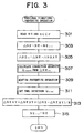
- FIG. 3 is a flow chart of the operation for correcting the fuel injection quantity for the purpose of preventing torsional vibrations according to this embodiment.
- the foregoing operation is performed as a routine executed by the ECU 30 whenever the crank shaft of the engine 1 rotates at a predetermined rotational angle (180° in this embodiment).
- the latest engine revolutions NE calculated in response to the pulse signal from the crank-angle sensor 35 and stored in the RAM of the ECU 30 are read in step 301. Moreover, the accelerator opening ACCP detected by the accelerator opening sensor 31 is read.
- step 303 the change rate ⁇ NE of the engine revolutions NE is calculated from Equation (4), where ⁇ NE i-1 represents the engine revolutions read during execution of the operation at the preceding process, ⁇ NE i-1 represents a value which is updated in step 315 at every execution of the foregoing operation.
- ⁇ NE ⁇ NE - ⁇ NE i-1
- step 305 the steady component ⁇ NEAV is subtracted from ⁇ NE calculated in step 303 in accordance with Equation (5) so that vibrations component ⁇ NE TV is calculated.
- the steady component ⁇ NEAV can be obtained by using the smoothing factor K to sequentially smooth ⁇ NE (step 313).
- ⁇ NE TV ⁇ NE - ⁇ NEAV
- step 307 the fuel injection correction quantity Q JRKFB is calculated in accordance with the calculated torsional vibration component ⁇ NE TV .
- the Q JRKFB is calculated as a value obtained by multiplying the torsional vibration component ⁇ NE TV with a negative constant ⁇ as expressed in Equation (6):
- Q JRKFB ⁇ ⁇ ⁇ NE TV ( ⁇ ⁇ 0)
- the value of the correction quantity Q JRKFB is set as the value which is increased in proportion to the variation (the change rate) in the revolutions caused by the torsional vibrations and which is inverse in sign. That is, when the revolutions caused by the torsional vibrations are being raised, the foregoing value is set to be a negative value to cancel the change. When the revolutions are being reduced, the foregoing value is set to be a positive value.
- step 309 After the fuel injection correction quantity Q JRKFB has been calculated as described above, a hunting preventive operation is performed in step 309. In step 309, it is determined whether or not there is a possibility of hunting. If it is determined that there is a possibility of hunting, the value of the correction quantity Q JRKFB is set to zero to inhibit correction of the fuel injection. The hunting preventive operation in step 309 will be described later.
- the correction quantity Q JRKFB is used to set the final fuel injection quantity Q FINC in step 311.
- the present value of the revolution change rate ⁇ NE is used to recalculate the value of the aforementioned steady component (the smoothing value) ⁇ NEAV.
- the value of NE i-1 is updated for the xt operation, and thus the foregoing operation is completed.
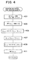
- FIG. 4 is a flow chart of an operation for setting the final fuel injection quantity Q FINC which is performed in step 311.
- step 401 the engine revolutions NE and the accelerator opening ACCP read in step 301 shown in FIG. 3 are used to read the required fuel injection quantity Q GOV from the numeric map stored in the ROM of the ECU 30.
- step 403 the value of NE is likewise used to read the guard value Q FULL for the fuel injection quantity from the numeric map stored in the ROM of the ECU 30.
- step 405 the basic fuel injection quantity Q BASE is set to the value either Q GOV or Q FULL whichever smaller in accordance with Equation (7).
- Q BASE MIN (Q GOV , Q FULL )
- step 407 the fuel injection correction quantity Q JRKFB which has been calculated in steps 307 and 309 shown in FIG. 3 and used to prevent torsional vibrations is used to set the fuel injection quantity Q FIN in accordance with Equation (8).
- Q FIN Q BASE + Q JRKFB
- this embodiment has a structure in which the value of Q FIN calculated in Equation (8) is limited again in step 309 using the guard value Q FULL .
- the final fuel injection quantity Q FINC is calculated.
- Q FINC MIN (Q FIN , Q FULL )
- step 411 the value of the final fuel injection quantity Q FINC is set for the fuel injection circuit, and the foregoing operation is completed.
- the fuel injection quantity to be supplied to the engine 1 is corrected to cancel the variation in the revolutions caused only by the torsional vibrations. Therefore, the torsional vibrations can be prevented without deteriorating the acceleration performance of the vehicle.
- the torsional vibration preventive control is performed in accordance with a variation in the revolutions (which is a variation in the revolutions for each cylinder of a 4-cylinder and 4-cycle engine used in this embodiment) detected whenever the crank shaft of the engine rotates at 180.
- the combustion conditions of the actual engine slightly differ depending on the respective cylinders even if no torsional vibration is being produced. Therefore, the output torque from the respective cylinders is different.
- the variation in the torque may fluctuate the engine revolutions in the explosion strokes of the respective cylinders in spite of the steady operating state.
- the variation component ⁇ NE TV is calculated whenever the crank shaft rotates at 180°. Since the 4-cylinder 4-cycle engine is used in this embodiment, the fuel injection is performed at an angular interval of 180°. Therefore, if the sign of ⁇ NE TV is inverted at each calculating operation (at each 180°), the fuel injection quantity has been corrected excessively, thus it is determined that the fuel injection quantity has been corrected excessively. As a result, it is determined that hunting has occurred. If the sign of ⁇ NE TV is positive in the previous calculating operation, the correction is performed to reduce the fuel injection quantity to decrease the revolutions.
- an influence of an error in detection exerted from influences of noise and disturbance is added to the foregoing patterns so that the hunting pattern as shown in FIG. 6 is preliminarily set.
- the hunting pattern shown in FIG. 6 will be described later.
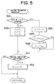
- FIG. 5 is a flow chart showing the hunting preventive operation which is performed in step 309 as shown in FIG. 3.
- step 501 it is determined whether or not the sign of ⁇ NE TV calculated in step 305 shown in FIG. 3 has been inverted from that calculated in the previous operation (whether or not the sign has been inverted). If the sign has not been inverted, the operation proceeds to step 505 where the count of a counter C 1 is increased by one. Steps 507 and 509 execute the limiting operation such that the value of the C 1 does not exceed the maximum value C MAX . As a result, the count of the counter C 1 is increased to the maximum value C MAX if the sign of the ⁇ NE TV is kept as being either positive or negative.
- step 501 If it is determined in step 501 that the sign of ⁇ NE TV has been inverted, the operation proceeds to step 503 where the values of counters C 2 and C 1 are substituted for the values of the counters C 3 and C 2 . Moreover, the value of the counter C 1 is set to one.
- step 511 hunting is determined in accordance with the counters C 1 , C 2 and C 3 . In step 511, it is determined whether or not there is a possibility of hunting in accordance with a map shown in FIG. 6.
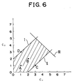
- FIG. 6 shows the map having an axis of ordinate as the values of the counter C 2 and an axis of abscissa as the values of the counter C 3 .
- the point A indicates reverse of the sign of ⁇ NE TV in each operation
- B indicates reverse of the sign of ⁇ NE TV once in two operations
- C and D indicate continuation of the same sign in three successive operations followed by the inverted sign only once.
- the above conditions are shown as the representative examples under which hunting occurs. That is, the points A to D on the map are basic conditions for determining occurrence of hunting. Therefore, in this embodiment, if the combination of the counters C 3 and C 2 satisfies any one of the points A to D, it is determined that the hunting has occurred. In an actual operation, the detection of the engine revolutions NE encounters an error owing to noise or disturbance. Therefore, determination on the possibility of hunting in accordance only with the basic conditions may not be accurately performed.
- the values of C 2 and C 3 are kept unchanged during proceeding of the operation from step 501 to step 505. Therefore, if hunting is determined once under the aforementioned determining conditions, the determination of hunting is not canceled even if the sign of ⁇ NE TV is no longer inverted. Therefore, in this embodiment, a condition in which the value of the counter C 1 is, in step 511, smaller than the value of the counter C 2 or C 3 is added to the conditions for determining hunting.
- the fact that the value of C 1 is smaller than the value of C 2 or C 3 represents that the number of times at which the ⁇ NE TV is kept to have the same sign has been decreased as compared with the previous number of times. That is, hunting is being strengthened. When the value of C 1 is larger than both values of C 2 and C 3 , it is determined that hunting has been eliminated.
- conditions under which occurrence of hunting is determined in step 511 shown in FIG. 5 are as follows: C 3 - 2 ⁇ C 2 ⁇ C 3 + 2; and C 2 + C 3 ⁇ 8; and C 1 ⁇ C 2 or C 1 ⁇ C 3
- step 511 When the counters C 1 , C 2 and C 3 satisfy the aforementioned conditions in step 511, that is, when there is a possibility of hunting at present, the operation proceeds to step 513 where the value of the correction quantity Q JRKFB set in step 307 shown in FIG. 3 is set to zero. As a result, the value of the final fuel injection quantity Q FINC set in step 409 shown in FIG. 4 coincides with the Q BASE .
- hunting is caused by the correction of the fuel injection quantity for the purpose of preventing torsional vibrations, resulting in a possibility of strengthened vibrations or unstable control. Therefore, the correction of the fuel injection quantity is not executed.
- step 511 If the values of the counters do not satisfy the aforementioned conditions in step 511 and there is no possibility of hunting, the value of the correction quantity Q JRKFB is kept unchanged and the operation is completed in this state. As a result, the correction of the fuel injection quantity for the purpose of preventing torsional vibrations is executed.
- the diagonal-line region shown in FIG. 6 is determined by experiments using an actual engine and an output shaft system.
- the correction quantity Q JRKFB is set to zero and the correction of the fuel injection quantity is not executed in case of a possibility of hunting.
- the control gain is reduced and the torsional vibrations are controlled to a certain degree while preventing hunting.
- Q JRKFB Q JRKFB ⁇ ⁇ ( ⁇ ⁇ 1)
- torsional vibrations can effectively be prevented without deteriorating the engine acceleration characteristics.
- An apparatus and a method for controlling fuel injection in an internal combustion engine (1) for preventing torsional vibrations of the engine without deteriorating the acceleration performance is disclosed.
- the apparatus is provided with a control unit (an ECU) (30) for controlling a fuel injection quantity for the diesel engine (1) of a vehicle (10).
- the ECU (30) calculates the change rate ⁇ NE of engine revolutions in accordance with an input from a crank angle sensor (35) and subtracts a value obtained by smoothing a variation component of ⁇ NE from the ⁇ NE so as to extract a torsional vibration component thereof.
- the ECU (30) corrects the fuel injection quantity of the engine to reduce the torsional vibration component.
- the extracted torsional vibration component does not contain steady change in the revolutions during acceleration or the like, the steady change in the revolutions caused only by the acceleration is not affected by the correction of the fuel injection quantity. Therefore, deterioration in the acceleration performance caused by prevention of the torsional vibrations can be prevented.
Landscapes
- Engineering & Computer Science (AREA)
- Chemical & Material Sciences (AREA)
- Combustion & Propulsion (AREA)
- Mechanical Engineering (AREA)
- General Engineering & Computer Science (AREA)
- Electrical Control Of Air Or Fuel Supplied To Internal-Combustion Engine (AREA)
- Combined Controls Of Internal Combustion Engines (AREA)
Applications Claiming Priority (2)
| Application Number | Priority Date | Filing Date | Title |
|---|---|---|---|
| JP23321998A JP3367429B2 (ja) | 1998-08-19 | 1998-08-19 | 内燃機関の燃料噴射制御装置 |
| JP23321998 | 1998-08-19 |
Publications (3)
| Publication Number | Publication Date |
|---|---|
| EP0980972A2 true EP0980972A2 (de) | 2000-02-23 |
| EP0980972A3 EP0980972A3 (de) | 2001-05-16 |
| EP0980972B1 EP0980972B1 (de) | 2007-03-28 |
Family
ID=16951633
Family Applications (1)
| Application Number | Title | Priority Date | Filing Date |
|---|---|---|---|
| EP19990110286 Expired - Lifetime EP0980972B1 (de) | 1998-08-19 | 1999-05-27 | Kraftstoffeinspritzsteuervorrichtung und -Verfahren für eine Brennkraftmaschine |
Country Status (3)
| Country | Link |
|---|---|
| EP (1) | EP0980972B1 (de) |
| JP (1) | JP3367429B2 (de) |
| DE (1) | DE69935639T2 (de) |
Cited By (2)
| Publication number | Priority date | Publication date | Assignee | Title |
|---|---|---|---|---|
| EP2719884A1 (de) * | 2012-10-09 | 2014-04-16 | Kabushiki Kaisha Toyota Jidoshokki | Steuerverfahren für einen Verbrennungsmotor |
| CN114060195A (zh) * | 2020-08-04 | 2022-02-18 | 北京福田康明斯发动机有限公司 | 一种降低发动机振动的方法、系统、存储介质和电子设备 |
Families Citing this family (9)
| Publication number | Priority date | Publication date | Assignee | Title |
|---|---|---|---|---|
| JP4822917B2 (ja) * | 2006-04-25 | 2011-11-24 | 富士重工業株式会社 | エンジン制御パラメータ調整システム |
| JP2007315203A (ja) * | 2006-05-23 | 2007-12-06 | Fuji Heavy Ind Ltd | エンジン制御装置 |
| SE537116C2 (sv) * | 2011-02-23 | 2015-01-20 | Scania Cv Ab | Dämpning av drivlineoscillationer |
| JP5949632B2 (ja) * | 2013-03-29 | 2016-07-13 | マツダ株式会社 | 内燃機関の制御装置 |
| JP6342322B2 (ja) * | 2014-12-22 | 2018-06-13 | ヤンマー株式会社 | エンジンの回転速度制御装置 |
| JP2017036673A (ja) * | 2015-08-06 | 2017-02-16 | 日本車輌製造株式会社 | 車両の動力伝達系回転制御装置 |
| JP6350974B2 (ja) * | 2016-03-30 | 2018-07-04 | マツダ株式会社 | エンジンの制御装置 |
| JP6233477B1 (ja) | 2016-09-09 | 2017-11-22 | マツダ株式会社 | 車両の制御装置 |
| JP2025084094A (ja) * | 2023-11-21 | 2025-06-02 | エムエーエヌ・エナジー・ソリューションズ・フィリアル・アフ・エムエーエヌ・エナジー・ソリューションズ・エスイー・ティスクランド | 船舶推進システム及びその制御方法 |
Family Cites Families (4)
| Publication number | Priority date | Publication date | Assignee | Title |
|---|---|---|---|---|
| JPS6026142A (ja) * | 1983-07-22 | 1985-02-09 | Toyota Motor Corp | デイ−ゼル機関のトルク制御装置 |
| US4928652A (en) * | 1987-09-17 | 1990-05-29 | Mazda Motor Corporation | Engine control system for suppressing car body vibration |
| FR2713286B1 (fr) * | 1993-11-30 | 1996-01-05 | Renault | Procédé de correction des à-coups de couple d'un moteur à combustion interne. |
| US5669354A (en) * | 1996-04-18 | 1997-09-23 | General Motors Corporation | Active driveline damping |
-
1998
- 1998-08-19 JP JP23321998A patent/JP3367429B2/ja not_active Expired - Fee Related
-
1999
- 1999-05-27 EP EP19990110286 patent/EP0980972B1/de not_active Expired - Lifetime
- 1999-05-27 DE DE1999635639 patent/DE69935639T2/de not_active Expired - Fee Related
Cited By (4)
| Publication number | Priority date | Publication date | Assignee | Title |
|---|---|---|---|---|
| EP2719884A1 (de) * | 2012-10-09 | 2014-04-16 | Kabushiki Kaisha Toyota Jidoshokki | Steuerverfahren für einen Verbrennungsmotor |
| US9194324B2 (en) | 2012-10-09 | 2015-11-24 | Kabushiki Kaisha Toyota Jidoshokki | Internal combustion engine control methods |
| CN114060195A (zh) * | 2020-08-04 | 2022-02-18 | 北京福田康明斯发动机有限公司 | 一种降低发动机振动的方法、系统、存储介质和电子设备 |
| CN114060195B (zh) * | 2020-08-04 | 2023-02-28 | 北京福田康明斯发动机有限公司 | 一种降低发动机振动的方法、系统、存储介质和电子设备 |
Also Published As
| Publication number | Publication date |
|---|---|
| EP0980972B1 (de) | 2007-03-28 |
| JP3367429B2 (ja) | 2003-01-14 |
| DE69935639T2 (de) | 2007-12-13 |
| DE69935639D1 (de) | 2007-05-10 |
| EP0980972A3 (de) | 2001-05-16 |
| JP2000064880A (ja) | 2000-02-29 |
Similar Documents
| Publication | Publication Date | Title |
|---|---|---|
| EP0924421B1 (de) | Kraftstoffeinspritz-Regelvorrichtung für eine Brennkraftmaschine | |
| US8272367B2 (en) | Control system for internal combustion engine | |
| US7877192B2 (en) | Control for an internal-combustion engine | |
| JPH0781935B2 (ja) | 多気筒内燃機関の失火検出装置 | |
| US6983735B2 (en) | Control apparatus for controlling the amount of intake air into an engine | |
| JPH0650077B2 (ja) | 内燃機関用燃料噴射量制御方法 | |
| KR100791163B1 (ko) | 내연 기관용 연료 분사 제어 장치 | |
| EP0980972B1 (de) | Kraftstoffeinspritzsteuervorrichtung und -Verfahren für eine Brennkraftmaschine | |
| US5759133A (en) | Method and engine control for suppressing vibration of the drive train in a motor vehicle | |
| JP3325162B2 (ja) | 内燃機関の燃焼状態検出装置 | |
| JP2621084B2 (ja) | アイドル回転数制御装置 | |
| US4909217A (en) | Electronic-type engine control method | |
| JP4135504B2 (ja) | 内燃機関の制御装置 | |
| JP4421381B2 (ja) | 内燃機関制御装置 | |
| JP2002332897A (ja) | 内燃機関の制御装置 | |
| JP3967700B2 (ja) | 内燃機関の燃料カットを制御する装置 | |
| EP1072778B1 (de) | Verfahren zur Regelung der Leerlaufdrehzahl einer Brennkraftmaschine | |
| JPS59188041A (ja) | 内燃エンジンの減速時燃料供給制御方法 | |
| EP0903257B1 (de) | Vorrichtung zur Momentregelung für eine auf einem Kraftfahrzeug montierte Brennkraftmaschine | |
| JPH08284734A (ja) | 火花点火式内燃機関の回転数計測装置 | |
| JP4738473B2 (ja) | 内燃機関のトルク制御装置 | |
| JP2586624B2 (ja) | 内燃機関の出力変動検出装置 | |
| JP3358624B2 (ja) | 内燃機関の燃料噴射制御装置 | |
| JP3089094B2 (ja) | 内燃機関の制御装置 | |
| JP2712798B2 (ja) | 内燃機関の燃料噴射量制御装置 |
Legal Events
| Date | Code | Title | Description |
|---|---|---|---|
| PUAI | Public reference made under article 153(3) epc to a published international application that has entered the european phase |
Free format text: ORIGINAL CODE: 0009012 |
|
| 17P | Request for examination filed |
Effective date: 19990527 |
|
| AK | Designated contracting states |
Kind code of ref document: A2 Designated state(s): DE FR GB IT |
|
| AX | Request for extension of the european patent |
Free format text: AL;LT;LV;MK;RO;SI |
|
| PUAL | Search report despatched |
Free format text: ORIGINAL CODE: 0009013 |
|
| AK | Designated contracting states |
Kind code of ref document: A3 Designated state(s): AT BE CH CY DE DK ES FI FR GB GR IE IT LI LU MC NL PT SE |
|
| AX | Request for extension of the european patent |
Free format text: AL;LT;LV;MK;RO;SI |
|
| AKX | Designation fees paid |
Free format text: DE FR GB IT |
|
| 17Q | First examination report despatched |
Effective date: 20040318 |
|
| GRAP | Despatch of communication of intention to grant a patent |
Free format text: ORIGINAL CODE: EPIDOSNIGR1 |
|
| GRAS | Grant fee paid |
Free format text: ORIGINAL CODE: EPIDOSNIGR3 |
|
| GRAA | (expected) grant |
Free format text: ORIGINAL CODE: 0009210 |
|
| AK | Designated contracting states |
Kind code of ref document: B1 Designated state(s): DE FR GB IT |
|
| REG | Reference to a national code |
Ref country code: GB Ref legal event code: FG4D |
|
| REF | Corresponds to: |
Ref document number: 69935639 Country of ref document: DE Date of ref document: 20070510 Kind code of ref document: P |
|
| ET | Fr: translation filed | ||
| PLBE | No opposition filed within time limit |
Free format text: ORIGINAL CODE: 0009261 |
|
| STAA | Information on the status of an ep patent application or granted ep patent |
Free format text: STATUS: NO OPPOSITION FILED WITHIN TIME LIMIT |
|
| 26N | No opposition filed |
Effective date: 20080102 |
|
| PGFP | Annual fee paid to national office [announced via postgrant information from national office to epo] |
Ref country code: IT Payment date: 20090520 Year of fee payment: 11 Ref country code: FR Payment date: 20090515 Year of fee payment: 11 Ref country code: DE Payment date: 20090527 Year of fee payment: 11 |
|
| PGFP | Annual fee paid to national office [announced via postgrant information from national office to epo] |
Ref country code: GB Payment date: 20090527 Year of fee payment: 11 |
|
| GBPC | Gb: european patent ceased through non-payment of renewal fee |
Effective date: 20100527 |
|
| REG | Reference to a national code |
Ref country code: FR Ref legal event code: ST Effective date: 20110131 |
|
| PG25 | Lapsed in a contracting state [announced via postgrant information from national office to epo] |
Ref country code: IT Free format text: LAPSE BECAUSE OF NON-PAYMENT OF DUE FEES Effective date: 20100527 |
|
| PG25 | Lapsed in a contracting state [announced via postgrant information from national office to epo] |
Ref country code: DE Free format text: LAPSE BECAUSE OF NON-PAYMENT OF DUE FEES Effective date: 20101201 |
|
| PG25 | Lapsed in a contracting state [announced via postgrant information from national office to epo] |
Ref country code: FR Free format text: LAPSE BECAUSE OF NON-PAYMENT OF DUE FEES Effective date: 20100531 |
|
| PG25 | Lapsed in a contracting state [announced via postgrant information from national office to epo] |
Ref country code: GB Free format text: LAPSE BECAUSE OF NON-PAYMENT OF DUE FEES Effective date: 20100527 |