EP0980992A1 - Drehzapfen für ein stufenloses Toroidgetriebe und Herstellungsverfahren für einen solchen Drehzapfen - Google Patents
Drehzapfen für ein stufenloses Toroidgetriebe und Herstellungsverfahren für einen solchen Drehzapfen Download PDFInfo
- Publication number
- EP0980992A1 EP0980992A1 EP99115692A EP99115692A EP0980992A1 EP 0980992 A1 EP0980992 A1 EP 0980992A1 EP 99115692 A EP99115692 A EP 99115692A EP 99115692 A EP99115692 A EP 99115692A EP 0980992 A1 EP0980992 A1 EP 0980992A1
- Authority
- EP
- European Patent Office
- Prior art keywords
- trunnion
- tool
- notch
- pulley groove
- axis
- Prior art date
- Legal status (The legal status is an assumption and is not a legal conclusion. Google has not performed a legal analysis and makes no representation as to the accuracy of the status listed.)
- Granted
Links
Images


Classifications
-
- F—MECHANICAL ENGINEERING; LIGHTING; HEATING; WEAPONS; BLASTING
- F16—ENGINEERING ELEMENTS AND UNITS; GENERAL MEASURES FOR PRODUCING AND MAINTAINING EFFECTIVE FUNCTIONING OF MACHINES OR INSTALLATIONS; THERMAL INSULATION IN GENERAL
- F16H—GEARING
- F16H15/00—Gearings for conveying rotary motion with variable gear ratio, or for reversing rotary motion, by friction between rotary members
- F16H15/02—Gearings for conveying rotary motion with variable gear ratio, or for reversing rotary motion, by friction between rotary members without members having orbital motion
- F16H15/04—Gearings providing a continuous range of gear ratios
- F16H15/06—Gearings providing a continuous range of gear ratios in which a member A of uniform effective diameter mounted on a shaft may co-operate with different parts of a member B
- F16H15/32—Gearings providing a continuous range of gear ratios in which a member A of uniform effective diameter mounted on a shaft may co-operate with different parts of a member B in which the member B has a curved friction surface formed as a surface of a body of revolution generated by a curve which is neither a circular arc centered on its axis of revolution nor a straight line
- F16H15/36—Gearings providing a continuous range of gear ratios in which a member A of uniform effective diameter mounted on a shaft may co-operate with different parts of a member B in which the member B has a curved friction surface formed as a surface of a body of revolution generated by a curve which is neither a circular arc centered on its axis of revolution nor a straight line with concave friction surface, e.g. a hollow toroid surface
- F16H15/38—Gearings providing a continuous range of gear ratios in which a member A of uniform effective diameter mounted on a shaft may co-operate with different parts of a member B in which the member B has a curved friction surface formed as a surface of a body of revolution generated by a curve which is neither a circular arc centered on its axis of revolution nor a straight line with concave friction surface, e.g. a hollow toroid surface with two members B having hollow toroid surfaces opposite to each other, the member or members A being adjustably mounted between the surfaces
-
- Y—GENERAL TAGGING OF NEW TECHNOLOGICAL DEVELOPMENTS; GENERAL TAGGING OF CROSS-SECTIONAL TECHNOLOGIES SPANNING OVER SEVERAL SECTIONS OF THE IPC; TECHNICAL SUBJECTS COVERED BY FORMER USPC CROSS-REFERENCE ART COLLECTIONS [XRACs] AND DIGESTS
- Y10—TECHNICAL SUBJECTS COVERED BY FORMER USPC
- Y10T—TECHNICAL SUBJECTS COVERED BY FORMER US CLASSIFICATION
- Y10T29/00—Metal working
- Y10T29/49—Method of mechanical manufacture
- Y10T29/49453—Pulley making
-
- Y—GENERAL TAGGING OF NEW TECHNOLOGICAL DEVELOPMENTS; GENERAL TAGGING OF CROSS-SECTIONAL TECHNOLOGIES SPANNING OVER SEVERAL SECTIONS OF THE IPC; TECHNICAL SUBJECTS COVERED BY FORMER USPC CROSS-REFERENCE ART COLLECTIONS [XRACs] AND DIGESTS
- Y10—TECHNICAL SUBJECTS COVERED BY FORMER USPC
- Y10T—TECHNICAL SUBJECTS COVERED BY FORMER US CLASSIFICATION
- Y10T74/00—Machine element or mechanism
- Y10T74/18—Mechanical movements
- Y10T74/18568—Reciprocating or oscillating to or from alternating rotary
- Y10T74/18832—Reciprocating or oscillating to or from alternating rotary including flexible drive connector [e.g., belt, chain, strand, etc.]
- Y10T74/18848—Reciprocating or oscillating to or from alternating rotary including flexible drive connector [e.g., belt, chain, strand, etc.] with pulley
Definitions
- the present invention relates to a trunnion of a toroidal continuously variable transmission for vehicles and a manufacturing process for the trunnion.
- Tokkai Hei 4-366049 published by the Japanese Patent Office in 1992 discloses a toroidal continuously variable transmission for vehicles wherein the ratio of the rotation speed of an input disk to the rotation speed of an output disk; i.e., a speed ratio, is continuously varied by varying the gyration angle of a pair of power rollers gripped between the input disk and output disk.
- the power rollers are respectively supported by trunnions at a position facing each other.
- Tokkai Hei 7-253145 published by the Japanese Patent Office in 1995 discloses a technique wherein a pulley is formed in the trunnions, and the trunnions are synchronously rotated by looping an endless wire around a pulley groove of the pulley.
- the slipping of the endless wire in the circumferential direction is prevented by engaging a large diameter part of the endless wire with a notch formed in a pulley groove. Therefore, in order to accurately synchronize the gyration angle of the trunnions, the notch must be formed precisely in the circumferential direction.
- the notch has to be machined after forming, but if the notch is machined by driving a tool in the axial direction while the trunnion is rotated around its rotation axis as the notch runs in a circumferential direction, the number of indexing steps of machining positions and positioning steps increases and the productivity declines.
- this invention provides a trunnion of a toroidal continuously variable transmission and a manufacturing process for the trunnion.
- the trunnion comprises a support having a hole therethrough comprising a pulley with a pulley groove and a notch crossing the pulley groove, a first shaft part on the top of the support, and a second shaft part on the bottom of the support that is coaxial with the first shaft part, the notch comprising an arc portion and two straight portions, one of the straight portion being formed on one side of the arc portion and the other of the straight portion being formed on the other side of the arc portion.
- the process comprises forming said pulley groove and said notch by forging casting or sintering, aligning a rotary tool for machining a flat surface by a blade provided on an end face so as to face a boundary interface between the pulley groove and notch, and rotating the tool while moving the tool forward in the axial direction of the tool so as to cut the boundary interface to a predetermined position.
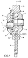
- a trunnion 3 comprises a support 3C which supports a power roller 1 such that it is free to rotate, and shaft parts 3A and 3B formed on the top and bottom of the support 3C.
- the support 3C and shaft parts 3A, 3B are formed in one piece by die forging.
- a through-hole 34 is formed in the support 3C.
- One end of a pivot shaft 2 is inserted in the through-hole 34, and the pivot shaft 2 pivots around an axis C.
- the power roller 1 is supported at the other end of the pivot shaft 2 via a radial bearing 19.
- An outer ring 18 and ball bearing 16 are interposed between the support 3C and power roller 1, and support a trust load.
- the power roller 1 When the trunnion 3 displaces in the direction of an axis 3Z, the power roller 1 gyrates between the input disk and output disk, not shown, and the ratio of the rotation speed of the input disk to the rotation speed of the output disk, i.e., the speed ratio, varies continuously.
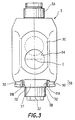
- the shaft part 3B is formed in a cylindrical shape, as shown in Fig. 2.
- a rod 6 of a hydraulic actuator, not shown, is inserted into the shaft part 3B.
- the rod 6 and trunnion 3 are joined by pressing a pin 36 into a pinhole 33 formed in the support 30 and a pinhole 35 formed in the rod 6 which are formed in the support 3C.
- a pulley 38 is formed in the lower part of the support 3C, as shown in Fig. 3.
- the pulley 38 comprises a pulley groove 30 and a notch 37 which crosses the pulley groove 30.
- An endless wire, not shown, is looped around the pulley groove 30 and notch 37 in order to synchronize the gyration angle of the trunnion 3, and the gyration angle of another trunnion, not shown, which is disposed facing the trunnion 3.
- the endless wire is provided with a large diameter part having a diameter larger than the wire gage, and this large diameter part engages with the notch 37 so that the endless wire does not slide in a circumferential direction relative to the trunnion 3.
- the pulley groove 30 and the notch 37 are formed in one piece with the support 3C when the trunnion 3 is formed by die forging.
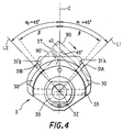
- angles ⁇ formed by the axis C of the pivot shaft 2 and boundary interfaces 31'A, 31'B between the notch 37 and the pulley groove 30 are less than 45 degrees, as shown in Fig. 4.
- the angles ⁇ are for example 39 degrees.
- the angles between the axis C of the pivot shaft 2 and the boundary interfaces 31A, 31B become ⁇ 1 , ⁇ 2 as shown in Fig. 5.
- the angles ⁇ 1 , ⁇ 2 are 45 degrees. Consequently, the angle of the notch 37 is enlarged from 2 ⁇ to 90 degrees after forging and the extension of the boundary interfaces 31A, 31B intersects perpendicularly on the axis 3Z of the trunnion 3.
- the rotary tool 90 can machine a flat surface by a blade provided on the tip surface.
- the tool 90 may be an end mill, for example.
- the first angle is 45 degrees.
- the tool 90 is then rotated while moving it forward in the axial direction, and cutting of the boundary interface 31'A is started.
- a line L1 which is at an angle of 45 degrees relative to the axis C of the pivot shaft 2, this line extending from the axis 3Z of the trunnion 3, cutting of the boundary interface 31'A is terminated.
- the tool 90 is refracted in the axial direction to prevent interference with the trunnion, the trunnion 3 is rotated countenclockwise in the figure, and the angle made by the axis of the tool 90 and the axis C of the pivot shaft 2 is adjusted to a second angle.
- the second angle is -45 degrees.
- the trunnion 3 is displaced parallel so as to face the tool 90.
- the tool 90 is then rotated while moving it forward in the axial direction, and cutting of the boundary interface 31'B on the left-hand side of the figure is started.
- this line L2 extending from the axis 3Z of the trunnion 3, cutting of the boundary interface 31'B is terminated.
- the angle made by the boundary interfaces 31A, 31B is precisely 90 degrees as shown in Fig. 5 due to the aforesaid double cutting by the tool 90.
- the shaded portions 32A, 32B in the figure are machining allowances removed by cutting. Accordingly, the shaded portions are formed straightly.
- the numerical values used for indexing the cutting position are 45 degrees and 90 degrees, and the work piece can be set easily and quickly.
- the machining time can be reduced. If two of the rotary tools 90 are available, the boundary interfaces 31'A, 31'B can be cut separately at the same time, in which case the machining time may be further reduced.
- angles ⁇ 1 , ⁇ 1 as formed the axis C of the pivot shaft 2 and the boundary interfaces 31A, 31B are arranged to be 45 degrees, but these angles may be different values.
- the angle ⁇ 1 is set to 30 degrees and the angle ⁇ 2 is set to 50 degrees
- the first and second angles during positioning may be set at respectively 30 degrees and 50 degrees relative to the axis C.
- the trunnion is formed by die forging in the aforesaid embodiment, it may be molded by casting or sintering instead.
Landscapes
- Engineering & Computer Science (AREA)
- General Engineering & Computer Science (AREA)
- Mechanical Engineering (AREA)
- Friction Gearing (AREA)
Applications Claiming Priority (2)
| Application Number | Priority Date | Filing Date | Title |
|---|---|---|---|
| JP22707398A JP3463568B2 (ja) | 1998-08-11 | 1998-08-11 | トラニオンの製造方法 |
| JP22707398 | 1998-08-11 |
Publications (2)
| Publication Number | Publication Date |
|---|---|
| EP0980992A1 true EP0980992A1 (de) | 2000-02-23 |
| EP0980992B1 EP0980992B1 (de) | 2003-04-23 |
Family
ID=16855108
Family Applications (1)
| Application Number | Title | Priority Date | Filing Date |
|---|---|---|---|
| EP99115692A Expired - Lifetime EP0980992B1 (de) | 1998-08-11 | 1999-08-09 | Drehzapfen für ein stufenloses Toroidgetriebe und Herstellungsverfahren für einen solchen Drehzapfen |
Country Status (4)
| Country | Link |
|---|---|
| US (1) | US6224508B1 (de) |
| EP (1) | EP0980992B1 (de) |
| JP (1) | JP3463568B2 (de) |
| DE (1) | DE69907092T2 (de) |
Cited By (1)
| Publication number | Priority date | Publication date | Assignee | Title |
|---|---|---|---|---|
| WO2004079226A1 (de) | 2003-03-04 | 2004-09-16 | Daimlerchrysler Ag | Toroidgetriebe |
Families Citing this family (4)
| Publication number | Priority date | Publication date | Assignee | Title |
|---|---|---|---|---|
| AU2002327801B2 (en) * | 2001-09-28 | 2008-03-06 | Stephen Ritland | Connection rod for screw or hook polyaxial system and method of use |
| JP4110406B2 (ja) * | 2003-09-25 | 2008-07-02 | 日本精工株式会社 | トロイダル型無段変速機のトラニオンの加工方法 |
| US9856962B2 (en) | 2006-03-24 | 2018-01-02 | Gkn Sinter Metals, Llc | Forged composite powder metal part and method of making same |
| US20070221005A1 (en) * | 2006-03-24 | 2007-09-27 | Gkn Sinter Metals, Inc. | Composite powder metal variable boundary gear and method |
Citations (4)
| Publication number | Priority date | Publication date | Assignee | Title |
|---|---|---|---|---|
| US4694704A (en) * | 1986-08-04 | 1987-09-22 | Excelermatic Inc. | Infinitely variable traction roller transmission |
| EP0248515A1 (de) * | 1986-04-08 | 1987-12-09 | de Pencier, Robert Dewey | Umkehrbarer, stufenlos veränderbarer Antrieb |
| JPH0634009A (ja) * | 1992-07-10 | 1994-02-08 | Mazda Motor Corp | トロイダル型無段変速機 |
| EP0882910A2 (de) * | 1997-06-05 | 1998-12-09 | Nissan Motor Company, Limited | Stufenloses Toroidgetriebe |
Family Cites Families (3)
| Publication number | Priority date | Publication date | Assignee | Title |
|---|---|---|---|---|
| JPH04366049A (ja) | 1991-06-12 | 1992-12-17 | Nissan Motor Co Ltd | 摩擦車式無段変速機 |
| JPH07253145A (ja) | 1994-03-15 | 1995-10-03 | Nissan Motor Co Ltd | トロイダル型無段変速機 |
| JPH09217803A (ja) * | 1996-02-13 | 1997-08-19 | Nissan Motor Co Ltd | 摩擦車式無段変速機 |
-
1998
- 1998-08-11 JP JP22707398A patent/JP3463568B2/ja not_active Expired - Lifetime
-
1999
- 1999-08-09 DE DE69907092T patent/DE69907092T2/de not_active Expired - Lifetime
- 1999-08-09 EP EP99115692A patent/EP0980992B1/de not_active Expired - Lifetime
- 1999-08-10 US US09/371,790 patent/US6224508B1/en not_active Expired - Lifetime
Patent Citations (4)
| Publication number | Priority date | Publication date | Assignee | Title |
|---|---|---|---|---|
| EP0248515A1 (de) * | 1986-04-08 | 1987-12-09 | de Pencier, Robert Dewey | Umkehrbarer, stufenlos veränderbarer Antrieb |
| US4694704A (en) * | 1986-08-04 | 1987-09-22 | Excelermatic Inc. | Infinitely variable traction roller transmission |
| JPH0634009A (ja) * | 1992-07-10 | 1994-02-08 | Mazda Motor Corp | トロイダル型無段変速機 |
| EP0882910A2 (de) * | 1997-06-05 | 1998-12-09 | Nissan Motor Company, Limited | Stufenloses Toroidgetriebe |
Non-Patent Citations (1)
| Title |
|---|
| PATENT ABSTRACTS OF JAPAN vol. 018, no. 254 (M - 1605) 16 May 1994 (1994-05-16) * |
Cited By (2)
| Publication number | Priority date | Publication date | Assignee | Title |
|---|---|---|---|---|
| WO2004079226A1 (de) | 2003-03-04 | 2004-09-16 | Daimlerchrysler Ag | Toroidgetriebe |
| US7524262B2 (en) | 2003-03-04 | 2009-04-28 | Daimler Ag | Toroidal power transmission |
Also Published As
| Publication number | Publication date |
|---|---|
| DE69907092T2 (de) | 2003-10-30 |
| JP3463568B2 (ja) | 2003-11-05 |
| US6224508B1 (en) | 2001-05-01 |
| JP2000055155A (ja) | 2000-02-22 |
| DE69907092D1 (de) | 2003-05-28 |
| EP0980992B1 (de) | 2003-04-23 |
Similar Documents
| Publication | Publication Date | Title |
|---|---|---|
| JP2000198025A (ja) | 精密機械工程および精密機械 | |
| US6224508B1 (en) | Trunnion of a toroidal continuously variable transmission and manufacturing process thereof | |
| EP1380365A1 (de) | Spindelmechanismus | |
| JP2000501656A (ja) | 回転フライス加工のための方法と装置 | |
| JP7413666B2 (ja) | 歯車加工方法 | |
| JP6998251B2 (ja) | 回転塑性加工用ローラ及びそれを備える回転塑性加工装置 | |
| US5823721A (en) | Method of producing an undercut, concave, self-contained bearing surface | |
| JP2000180154A (ja) | 位相合わせ方法 | |
| EP0703387B1 (de) | Verfahren zur Formgebung der Nockenoberfläche eines Bauteils einer Nockenvorspanneinrichtung für ein stufenlos verstellbares Toroid-Getriebe | |
| EP0985850B1 (de) | Drehzapfen für ein stufenloses Toroidgetriebe und Herstellungsverfahren für einen solchen Drehzapfen | |
| JP2000141120A (ja) | トロコイド工具およびトロコイド工具による加工法 | |
| JPS6399136A (ja) | ピストリングの製造方法および装置 | |
| JP2000052217A (ja) | 工具と加工方法 | |
| RU2268108C1 (ru) | Способ и устройство для обработки некруглых отверстий | |
| JP2021160069A (ja) | 加工工具及び加工装置 | |
| JP2564081Y2 (ja) | パイプ面取加工装置 | |
| EP0303432A2 (de) | Verfahren zur plastischen Bearbeitung und Vorrichtung dazu | |
| JPH1177469A (ja) | カムシャフト加工機の位相位置決め装置 | |
| JP2827209B2 (ja) | 円筒体の切断加工法 | |
| CN121551656A (zh) | 一种数控车床软爪车削夹具及软爪自定心方法 | |
| JP3348750B2 (ja) | 曲面板の孔の裏面加工装置及び方法 | |
| JP2026049142A (ja) | カム溝,その加工装置,その加工方法 | |
| WO2019106844A1 (ja) | デフケース加工用の刃具、デフケースの加工機及びデフケースの加工方法 | |
| JP2006289871A (ja) | 輪帯光学素子の製造方法および輪帯光学素子用金型の製造方法 | |
| JP2002103188A (ja) | 端面研削加工方法及び端面研削装置 |
Legal Events
| Date | Code | Title | Description |
|---|---|---|---|
| PUAI | Public reference made under article 153(3) epc to a published international application that has entered the european phase |
Free format text: ORIGINAL CODE: 0009012 |
|
| 17P | Request for examination filed |
Effective date: 19990809 |
|
| AK | Designated contracting states |
Kind code of ref document: A1 Designated state(s): DE FR GB |
|
| AX | Request for extension of the european patent |
Free format text: AL;LT;LV;MK;RO;SI |
|
| AKX | Designation fees paid |
Free format text: DE FR GB |
|
| 17Q | First examination report despatched |
Effective date: 20020131 |
|
| GRAH | Despatch of communication of intention to grant a patent |
Free format text: ORIGINAL CODE: EPIDOS IGRA |
|
| GRAH | Despatch of communication of intention to grant a patent |
Free format text: ORIGINAL CODE: EPIDOS IGRA |
|
| GRAA | (expected) grant |
Free format text: ORIGINAL CODE: 0009210 |
|
| AK | Designated contracting states |
Designated state(s): DE FR GB |
|
| REG | Reference to a national code |
Ref country code: GB Ref legal event code: FG4D |
|
| REF | Corresponds to: |
Ref document number: 69907092 Country of ref document: DE Date of ref document: 20030528 Kind code of ref document: P |
|
| ET | Fr: translation filed | ||
| PLBE | No opposition filed within time limit |
Free format text: ORIGINAL CODE: 0009261 |
|
| STAA | Information on the status of an ep patent application or granted ep patent |
Free format text: STATUS: NO OPPOSITION FILED WITHIN TIME LIMIT |
|
| 26N | No opposition filed |
Effective date: 20040126 |
|
| REG | Reference to a national code |
Ref country code: FR Ref legal event code: PLFP Year of fee payment: 18 |
|
| REG | Reference to a national code |
Ref country code: FR Ref legal event code: PLFP Year of fee payment: 19 |
|
| REG | Reference to a national code |
Ref country code: FR Ref legal event code: PLFP Year of fee payment: 20 |
|
| PGFP | Annual fee paid to national office [announced via postgrant information from national office to epo] |
Ref country code: FR Payment date: 20180712 Year of fee payment: 20 Ref country code: DE Payment date: 20180724 Year of fee payment: 20 |
|
| PGFP | Annual fee paid to national office [announced via postgrant information from national office to epo] |
Ref country code: GB Payment date: 20180808 Year of fee payment: 20 |
|
| REG | Reference to a national code |
Ref country code: DE Ref legal event code: R071 Ref document number: 69907092 Country of ref document: DE |
|
| REG | Reference to a national code |
Ref country code: GB Ref legal event code: PE20 Expiry date: 20190808 |
|
| PG25 | Lapsed in a contracting state [announced via postgrant information from national office to epo] |
Ref country code: GB Free format text: LAPSE BECAUSE OF EXPIRATION OF PROTECTION Effective date: 20190808 |