EP0981143A2 - Mécanisme de blocage pour outil à moteur - Google Patents
Mécanisme de blocage pour outil à moteur Download PDFInfo
- Publication number
- EP0981143A2 EP0981143A2 EP99306211A EP99306211A EP0981143A2 EP 0981143 A2 EP0981143 A2 EP 0981143A2 EP 99306211 A EP99306211 A EP 99306211A EP 99306211 A EP99306211 A EP 99306211A EP 0981143 A2 EP0981143 A2 EP 0981143A2
- Authority
- EP
- European Patent Office
- Prior art keywords
- power tool
- switch
- locking member
- housing
- handle
- Prior art date
- Legal status (The legal status is an assumption and is not a legal conclusion. Google has not performed a legal analysis and makes no representation as to the accuracy of the status listed.)
- Granted
Links
Images


Classifications
-
- H—ELECTRICITY
- H01—ELECTRIC ELEMENTS
- H01H—ELECTRIC SWITCHES; RELAYS; SELECTORS; EMERGENCY PROTECTIVE DEVICES
- H01H13/00—Switches having rectilinearly-movable operating part or parts adapted for pushing or pulling in one direction only, e.g. push-button switch
- H01H13/02—Details
- H01H13/04—Cases; Covers
- H01H13/08—Casing of switch constituted by a handle serving a purpose other than the actuation of the switch
-
- H—ELECTRICITY
- H01—ELECTRIC ELEMENTS
- H01H—ELECTRIC SWITCHES; RELAYS; SELECTORS; EMERGENCY PROTECTIVE DEVICES
- H01H3/00—Mechanisms for operating contacts
- H01H3/02—Operating parts, i.e. for operating driving mechanism by a mechanical force external to the switch
- H01H3/20—Operating parts, i.e. for operating driving mechanism by a mechanical force external to the switch wherein an auxiliary movement thereof, or of an attachment thereto, is necessary before the main movement is possible or effective, e.g. for unlatching, for coupling
-
- H—ELECTRICITY
- H01—ELECTRIC ELEMENTS
- H01H—ELECTRIC SWITCHES; RELAYS; SELECTORS; EMERGENCY PROTECTIVE DEVICES
- H01H9/00—Details of switching devices, not covered by groups H01H1/00 - H01H7/00
- H01H9/02—Bases, casings, or covers
- H01H9/06—Casing of switch constituted by a handle serving a purpose other than the actuation of the switch, e.g. by the handle of a vacuum cleaner
Definitions
- This invention relates to a switch lockout mechanism for a power tool, and, more particularly, to a mechanism that locks the power switch in an "off' position and requires an operator to actuate a separate lever to orient the switch to its "on" position.
- Power tools such as circular saws
- a handle molded into the body of the tool.
- Such a handle is grasped by the power tool operator to guide and propel the tool through the workpiece.
- a rear handle and a forward handle.
- the rear handle oftentimes resembles a pistol-type grip.
- the handle extends upwardly and forwardly and is separated from the body of the saw so that the operator can easily grasp an elongated handle section that fits easily within the hand of the operator.
- This handle section typically extends in a direction that is generally parallel to and along the line of travel of the saw.
- the on/off switch for the saw located so that it can be actuated by at least the index and middle fingers of the operator's hand engaging the handle. Such an arrangement allows an operator to selectively start and stop the cutting operation of the saw while having his/her hand gripping the handle.
- Prior lockout mechanisms or latches typically are of two main types, a pivoting type and a sliding type.
- a pivot type arrangement the latch is pivotally mounted within the handle structure about an axis which is transverse or perpendicular to the elongated direction of the handle.
- the latch In the case of a circular saw, the latch is pivotally mounted about an axis that is parallel to the axis of rotation of the saw blade.
- These latches operate by pivoting between an engaged position wherein the handle switch contacts the latch member and is prevented from movement to its "on" position, and a disengaged position wherein the operator is allowed to actuate the switch to the "on” position. Examples of these transverse pivotal lockout mechanisms can be found in U.S. Patent No.
- a still further disadvantage of these references is the location of the lockout mechanism actuating button above or behind the on/off switch with respect to the longitudinal axis of the handle. More specifically, when a person typically grabs a handle, the tendency is for the thumb to be forward of the index and middle fingers. To actuate the lockout mechanism buttons of these references, the thumb must be moved rearwardly to push the actuating button, thus presenting a potential awkward position for the saw operator, and, further, possibly resulting in unnecessary reorientation of the thumb along the side of the handle to the normal gripping position.
- the second type of lockout mechanism includes a latch member which, when actuated, slides within the handle housing to allow actuation of the on/off switch by the operator.
- An example of this type of sliding latch member is disclosed in U.S. Patent No. 5,638,945.
- These sliding lockout mechanisms are oftentimes relatively complicated and do not allow ergonomic positioning of the thumb during the beginning power tool operation. More specifically, the structure of the above reference, again, has the actuating switch positioned on the top surface of a handle housing and at a location that is above the actuating switch for the power tool.
- this sliding-type mechanism is highly disadvantageous because it requires the operator to utilize significant effort to reposition his or her thumb in a normal gripping operation, and also has the sliding actuating switch or button located directly above the on/off switch which is typically not a normal position for a hand gripping the handle.
- a still further disadvantage of all the above lockout mechanisms is the structure used to bias the lockout mechanism back to its original locked position.
- the prior mechanisms tend to utilize leaf springs or deformable arms to supply the biasing force.
- These types of biasing structures are disadvantageous because the spring force of the structure increases generally from zero along a generally linear type path with further deformation of the spring or arm. In other words, as these springs become more deformed, they offer more resistance. As is apparent, this is disadvantageous to an operator because his/her thumb must increase force with further actuation of the lockout button or lever, thus again causing more uncertainty, and less stability during initial cutting operations.
- Some prior art structures also utilize coil springs compressed along their central axis. These coil springs compressed in this way also have a generally linear spring force curve and are disadvantageous for the same reasons as the other biasing structures.
- Another object of the present invention is to provide a lockout mechanism for a power tool wherein an advantageous lockout mechanism actuating lever is accessible equally to both left-handed and right-handed power tool operators.
- a still further object of the present invention is to provide a lockout mechanism for a power tool, wherein the actuating lever allows an operator's thumb to slide easily and quickly to a normal gripping orientation about the power tool handle.
- a further object of the present invention is to provide a lockout mechanism for a power tool, wherein the actuating lever of the lockout mechanism is located at a more natural longitudinal location on the handle with respect to the on/off switch of the power tool so as to allow easier operation.
- Yet another object of the present invention is to provide a lockout mechanism of a power tool that is easily assembled and has a minimum number of parts.
- a still further object of the present invention is to provide a lockout mechanism utilizing a spring member that does not require precompressing or stretching during the assembly of the lockout mechanism.
- Another object of the present invention is to provide a lockout mechanism utilizing a spring member that subjects an operator's thumb to generally consistent force during operation.
- a power tool comprising:
- the invention further includes a lockout mechanism for a power tool wherein the locking member has a third rotatable position that is in a rotational direction opposite to the direction that said locking member is rotated in from its first position to its second position.
- the third position also allows the switch to be actuated to its "on" position.
- the present invention is further directed to the structure as described above, including a biasing element for urging the locking member toward its first rotatable position from both the second and third rotatable positions.
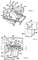
- Saw 20 has a housing assembly 22 in which is disposed a motor for powering a blade 24. Blade 24 is generally surrounded by an upper stationary guard 26 and a lower movable guard 28. Saw 20 also has a generally planar base or shoe 30 attached to stationary guard 26. Base 30 rests on the upper surface of the workpiece as the saw passes therethrough and is used to gauge the depth to which blade 24 cuts.
- Saw 20 further includes a rear trigger handle 32 and a forward brace handle 34.
- the trigger handle 32 has a power switch 36 mounted therein for operation by one hand of the saw user.
- the other hand of the saw user is positioned on brace handle 34 which allows the user to further control the saw as it passes through a workpiece.
- Trigger handle 32 has a generally hollow housing 38 which is formed in a clamshell fashion by two half sections 39.
- Housing 38 has a gripping portion 40 which fits within the palm of an operator during operation, and generally extends in an elongated direction along an axis 42, as best shown in Figs. 2 and 3.
- Axis 42 is generally at an angle to the plane of base 30 and slopes downwardly in a direction from a forward end of the saw toward a rearward end of the saw.
- Power switch 36 is received within a generally rectangular mounting section or boss 44 of each of the clamshell halves 39 of housing 38.
- Switch 36 has a trigger 46 extending through an aperture 48 within housing 38 that allows actuation by the index and middle finger of an operator in a generally upwardly direction such that electrical connections can be made within switch 36 to connect the power supply of the saw with the saw motor resulting in rotation of the blade.
- Trigger 46 is generally internally biased toward its disengaged or "off" position.
- Trigger 46 generally is of a solid construction, as shown in Fig. 5, but has a pair of hollow chambers 50 formed adjacent a forward end, which are separated by a locking abutment or ridge 52.
- the upper surface 54 of ridge 52 serves as the engaging surface with a lockout mechanism 56, also disposed within housing 38.
- the hollowed portions of chamber 50 on each side of ridge 52 act as clearance areas to allow actuation of trigger 46, as is shown in Fig. 6.
- Lockout mechanism 56 includes an elongated cylindrical locking shaft 58 and a biasing coil spring 60.
- Lockout shaft 58 as best shown in Figs. 3, 5, 6 and 7, includes a locking fin 62 positioned and integrally formed on one end, and an oversized actuating cylinder 64 formed on an opposite end.
- Cylinder 64 and shaft 58 are rotatably or pivotally received within the clamshell halves 39 of housing 38 via appropriate generally semicircular shaped bosses formed in each housing half 39.
- the end of shaft 58 located adjacent fin 62 is received in a pivotally/rotatably supporting boss 66.
- the entire actuating cylinder 64 is received in a generally semicircular boss 68.
- Boss 68 almost completely surrounds cylinder 64 when the clamshell halves 39 of housing 38 are put together, thus allowing rotation of shaft 58 and cylinder 64 about an axis 70 which is generally aligned with and parallel to the axis 42 of gripping portion 40.
- locking fin 62 has a lower surface 72 which engages surface 54 or ridge 52 when trigger 46 is in its locked-out position. Still further, fin 62 is received within either of chambers 50 of trigger 46 to allow actuation of the trigger to its "on" position, as will be more fully described below.
- Actuating cylinder 64 has positioned on its peripheral surface 74 actuating levers 76 at diametrically opposed locations. As best shown in Fig. 4, each lever 76 extends through an aperture 78 formed in each of the clamshell halves 39 of housing 38. Apertures 78 are generally rectangular in shape and allow movement of levers 76 therein in both generally upwardly and downwardly rotations, as indicated by the arrows and phantom line locations in Fig. 4. Therefore, rotation of either lever 76 within aperture 78 will result in rotation of shaft 58 and thus fin 62. This rotating action results in mechanism 56 obtaining its disengaged or unlocked position, as will be more fully described below.
- Coil spring 60 is also received within housing 38 via generally semicircular bosses 80 formed in clamshell halves 39, as best shown in Figs. 3 and 7.
- the lower half portion 82 of spring 60 is snugly received in a generally cylindrical chamber formed by bosses 80.
- a suitable chamber 84 is formed in housing 38 which allows the top half 86 of spring 60 to be deformed in a left or right direction with respect to axes 42 and 70, as best shown in Figs. 8 and 9.
- Upper half 86 of spring 60 is coupled to shaft 58 via circumferential protrusion 88 having a generally spherical coupling end 90. End 90 is received within the hollow interior of spring 60, as best shown in Fig. 7.
- Spherical end 90 allows a smooth rotating action of protrusion 88 with respect to spring 60 when shaft 58 is rotated so as to deform spring 60.
- spring 60 has an upwardly extending leg 92 which is received in an aperture 94 formed in an end planar surface 65 of actuating cylinder 64.
- Leg 92 serves as an additional attachment to shaft 58 and cylinder 64.
- spring 60 through its protrusion 88 and leg 92, serves to bias fin 62 to its locked position from its disengaged/unlocked positions resulting from rotation of shaft 58 in either direction via lever 76.
- the lockout mechanism 56 is shown in its locked position which will prevent an operator from actuating trigger 46 upwardly to result in rotation of blade 24. More specifically, locking fin 62 of locking shaft 58 engages ridge 52 of trigger 46, as best shown in Fig. 5, and prevents upward movement of trigger 46. Additionally, in this position, spring 60 is in its natural unbiased state and is not exerting any biasing pressure on shaft 58 or actuating cylinder 64. Therefore, in this position if an operator grips portion 40 of housing 38 and attempts to actuate trigger 46 with his or her index and middle finger, such actuation will be prevented so that the saw cannot be turned to its "on" position.
- an operator wishes to position trigger 46 in its depressed or "on" position, the operator must first position his or her thumb on one of the actuating levers 76 extending through the apertures 78 in housing 38. More specifically, an operator can grip portion 40 easily within his or her hand and position the index and middle fingers on trigger 46. Portion 40 can rest easily within the palm of the operator and the thumb of the hand gripping portion 40 can be positioned along the side surface of housing 38 forwardly of the index and middle finger in the natural and stable gripping configuration. The thumb engages the top surface of the lever 76 on the side the thumb is on, and can exert downward pressure on the lever so as to rotate cylinder 64 and shaft 58. This rotation of shaft 58 will result in rotation of locking fin 62, as best shown in Fig.
- an advantage of the present invention is the feature that rotation of the locking mechanism in any direction results in the locking mechanism moving from its locked to unlocked position.
- This allows levers on either side of housing 38, and thus allows easy accommodation of both left-handed and right-handed saw operators.
- levers 76 located on either side of housing 38 provide comfortable positions for either a left-handed or right-handed saw operator's thumbs during the initial cutting operations and easy transition from the initial operations requiring actuation of mechanism 56 to a full grip about handle portion 40.
- the top surface of lever 76 becomes slanted downwardly and easily allows the user's thumb to slide off of lever 76 and go to its natural position.
- the bias of the mechanism attempts to return lever 76 to its locked position.
- the rotation or orientation of shaft 58 generally along the longitudinal orientation of handle portion 40 allows flexibility, in that an operator can even, if so desired, push upwardly along one of levers 76 which will still result in the mechanism obtaining its disengaged unlocked position.
- a still further advantage found in the present invention is the location of actuating lever 76 ahead of trigger 46, such as to allow the thumb of an operator to obtain a more natural position and to quickly obtain a gripping position after actuating the mechanism. In prior art mechanisms, it was oftentimes necessary to locate the structure of the lockout mechanism as close as possible to the switch in order to obtain mechanical advantages, or to utilize sliding or camming surfaces.
- lever 76 can be positioned at any desirable point ahead of the trigger, and all that is necessary is that access or space be available within the handle for the shaft and fin 62.
- shaft 58 rotating generally along the axis of the handle allows flexibility in deciding where to put the actuating levers and biasing structures.
- mechanism 56 also provides a very easily assembled, simple lockout mechanism for a power switch.
- mechanism 56 can be comprised essentially of two parts. Fin 62, shaft 58, cylinder 64, and levers 76 can all be molded as a one-piece part, which can be easily dropped into the relevant bosses formed in the clamshell structure of housing 38.
- Coil spring 60 can easily be assembled with such part and also dropped within the relevant bosses of housing 38 during manufacture. It is also a noticeable advantage that spring 60 does not require any precompressing or pretensioning during assembly. Such precompressing or pretensioning of a spring during assembly oftentimes requires certain skill and patience when putting parts together.
- An additional advantage of the present invention is the sideward deformation of coil spring 60.
- the present lockout mechanism provides an easily assembled simple mechanism which is ergonomically advantageous to an operator and which allows the operator to easily assume the normal gripping orientation as quickly as possible after actuating the lockout mechanism.
Landscapes
- Sawing (AREA)
- Portable Power Tools In General (AREA)
- Automatic Tool Replacement In Machine Tools (AREA)
- Manipulator (AREA)
- Switch Cases, Indication, And Locking (AREA)
- Details Of Spanners, Wrenches, And Screw Drivers And Accessories (AREA)
Priority Applications (1)
| Application Number | Priority Date | Filing Date | Title |
|---|---|---|---|
| EP05022989A EP1617444A1 (fr) | 1998-08-14 | 1999-08-05 | Mécanisme de blocage pour outil à moteur |
Applications Claiming Priority (2)
| Application Number | Priority Date | Filing Date | Title |
|---|---|---|---|
| US134321 | 1987-12-17 | ||
| US09/134,321 US6091035A (en) | 1998-08-14 | 1998-08-14 | Lockout mechanism for power tool |
Related Child Applications (1)
| Application Number | Title | Priority Date | Filing Date |
|---|---|---|---|
| EP05022989A Division EP1617444A1 (fr) | 1998-08-14 | 1999-08-05 | Mécanisme de blocage pour outil à moteur |
Publications (4)
| Publication Number | Publication Date |
|---|---|
| EP0981143A2 true EP0981143A2 (fr) | 2000-02-23 |
| EP0981143A3 EP0981143A3 (fr) | 2000-09-06 |
| EP0981143B1 EP0981143B1 (fr) | 2006-05-10 |
| EP0981143B9 EP0981143B9 (fr) | 2007-01-03 |
Family
ID=22462827
Family Applications (2)
| Application Number | Title | Priority Date | Filing Date |
|---|---|---|---|
| EP05022989A Withdrawn EP1617444A1 (fr) | 1998-08-14 | 1999-08-05 | Mécanisme de blocage pour outil à moteur |
| EP99306211A Expired - Lifetime EP0981143B9 (fr) | 1998-08-14 | 1999-08-05 | Mécanisme de blocage pour outil à moteur |
Family Applications Before (1)
| Application Number | Title | Priority Date | Filing Date |
|---|---|---|---|
| EP05022989A Withdrawn EP1617444A1 (fr) | 1998-08-14 | 1999-08-05 | Mécanisme de blocage pour outil à moteur |
Country Status (7)
| Country | Link |
|---|---|
| US (3) | US6091035A (fr) |
| EP (2) | EP1617444A1 (fr) |
| CN (1) | CN1143759C (fr) |
| AT (1) | ATE326061T1 (fr) |
| CA (1) | CA2280227C (fr) |
| DE (1) | DE69931225T2 (fr) |
| DK (1) | DK0981143T3 (fr) |
Cited By (4)
| Publication number | Priority date | Publication date | Assignee | Title |
|---|---|---|---|---|
| EP1387376A1 (fr) * | 2002-08-02 | 2004-02-04 | Black & Decker Inc. | Verrou-arrêt pour interrupteur d'outils |
| GB2495210A (en) * | 2011-09-30 | 2013-04-03 | Bosch Gmbh Robert | Lockout forward flip lever for a power saw |
| WO2021259987A1 (fr) * | 2020-06-25 | 2021-12-30 | Festool Gmbh | Scies circulaires avec ensembles verrous |
| EP2794193B1 (fr) * | 2011-12-21 | 2022-03-16 | Robert Bosch Tool Corporation | Procédé et mécanisme pour verrouillage d'outil électrique |
Families Citing this family (22)
| Publication number | Priority date | Publication date | Assignee | Title |
|---|---|---|---|---|
| US6091035A (en) * | 1998-08-14 | 2000-07-18 | Black & Decker, Inc. | Lockout mechanism for power tool |
| US6057518A (en) * | 1998-08-14 | 2000-05-02 | Black & Decker, Inc. | Lockout mechanism for power tool |
| US6274828B1 (en) * | 2000-02-22 | 2001-08-14 | Defond Manufacturing Limited | On-off switch with off position locking actuator |
| US6714049B2 (en) | 2001-08-10 | 2004-03-30 | Shakti Systems, Inc. | Logic state transition sensor circuit |
| US6653584B1 (en) * | 2002-05-24 | 2003-11-25 | Rexon Co., Ltd. | Successive switch device of a slot cutting machine |
| CA2397024C (fr) * | 2002-08-07 | 2008-02-19 | Edward M. Turley | Mecanisme d'interrupteur pour meuleuse reversible |
| USD489591S1 (en) | 2002-10-01 | 2004-05-11 | Milwaukee Electric Tool Corporation | Circular saw |
| US6753490B2 (en) * | 2002-10-16 | 2004-06-22 | S-B Power Tool Corporation | Ambidextrous switch lockout system |
| GB2395460B8 (en) * | 2002-11-22 | 2013-02-06 | Bosch Gmbh Robert | Electric hand tool machine |
| US20060090354A1 (en) * | 2005-03-28 | 2006-05-04 | Gongola Andrew G | Power tool, such as a circular saw |
| US8393835B2 (en) * | 2009-06-16 | 2013-03-12 | Robert Bosch Gmbh | Detachable operating handle for a power tool |
| US8598477B2 (en) | 2009-10-13 | 2013-12-03 | Barton L. Garvin | Universal switch restraint device |
| US8937259B2 (en) | 2009-10-13 | 2015-01-20 | Barton L. Garvin | Universal electrical circuit breaker locking device |
| WO2014093523A1 (fr) * | 2012-12-11 | 2014-06-19 | Robert Bosch Gmbh | Scie circulaire équipée d'un système émetteur de lumière |
| DE102012223931A1 (de) * | 2012-12-20 | 2014-06-26 | Robert Bosch Gmbh | Werkzeugmaschine mit einer Schaltereinrichtung |
| US10014128B2 (en) * | 2013-12-17 | 2018-07-03 | Robert Bosch Tool Corporation | Portable power tool with trigger switch, trigger release and lock-on mechanism combination |
| EP3792008B1 (fr) | 2019-09-12 | 2024-05-01 | Andreas Stihl AG & Co. KG | Appareil de travail portatif doté d'un outil |
| DE102019216865A1 (de) * | 2019-10-31 | 2021-05-06 | Robert Bosch Gmbh | Handwerkzeugmaschine |
| EP3822033A1 (fr) | 2019-11-14 | 2021-05-19 | Hilti Aktiengesellschaft | Procédé de commande et de réglage d'une machine-outil |
| EP3822031A1 (fr) * | 2019-11-14 | 2021-05-19 | Hilti Aktiengesellschaft | Procédé de commande et de régulation d'une machine-outil |
| CN113841527A (zh) * | 2021-10-28 | 2021-12-28 | 淮阴工学院 | 一种多形状适配型修剪器 |
| CN113892359B (zh) * | 2021-10-29 | 2023-10-03 | 淮阴工学院 | 移动式自动化市政园林修剪设备 |
Family Cites Families (56)
| Publication number | Priority date | Publication date | Assignee | Title |
|---|---|---|---|---|
| US30270A (en) * | 1860-10-02 | Hew-cleaner | ||
| US1929662A (en) * | 1930-08-16 | 1933-10-10 | Wappat Inc | Motor driven tool switch |
| US3331406A (en) | 1964-03-03 | 1967-07-18 | Joseph C Christophel | Radial saw |
| US3383943A (en) * | 1966-07-08 | 1968-05-21 | Cutler Hammer Inc | All-speed lever lock |
| US3626118A (en) * | 1966-11-14 | 1971-12-07 | Harold R Botefuhr | Radial arm saw with a depressible key for unlocking a switch-actuating trigger |
| US3422296A (en) * | 1967-01-03 | 1969-01-14 | Emerson Electric Co | Interlock reversing switch |
| US3461556A (en) * | 1967-07-10 | 1969-08-19 | Sunbeam Corp | Trigger switch for electric appliance |
| US3376402A (en) * | 1967-09-25 | 1968-04-02 | Black & Decker Mfg Co | Reversible electric switch with laterally extending reversing member for use in portable electric tool or appliance |
| US3579002A (en) * | 1970-03-31 | 1971-05-18 | Black & Decker Mfg Co | Reversing switch for power tools |
| US3746815A (en) | 1971-11-03 | 1973-07-17 | Cutler Hammer Inc | Off locking trigger switches |
| US3780246A (en) * | 1972-08-22 | 1973-12-18 | Black & Decker Mfg Co | Hand-operated tool with switch actuator having three-position lock-off assembly |
| DE2254554C3 (de) * | 1972-11-08 | 1979-08-30 | Licentia Patent-Verwaltungs-Gmbh, 6000 Frankfurt | Einschalter für eine elektromotorisch angetriebene Handwerkzeugmaschine |
| USRE30270E (en) | 1972-12-18 | 1980-05-06 | Eaton Corporation | Off locking in-line trigger switch |
| DE7321450U (de) * | 1973-06-08 | 1973-09-06 | Metabowerke Kg | Schalter für ein elektromotorisch betriebenes Handwerkzeug |
| US3873796A (en) * | 1973-07-06 | 1975-03-25 | Black & Decker Mfg Co | Trigger mechanism for hand-operated power device including independently operable locking devices providing automatic lock off and manual lock-on operation |
| JPS5078998A (fr) * | 1973-11-15 | 1975-06-27 | ||
| US3952239A (en) * | 1974-08-23 | 1976-04-20 | The Black And Decker Manufacturing Company | Modular cordless tools |
| US3973179A (en) | 1974-08-23 | 1976-08-03 | The Black And Decker Manufacturing Company | Modular cordless tools |
| US3971906A (en) * | 1974-11-01 | 1976-07-27 | Lucerne Products, Inc. | Trigger-lock control |
| DE2601269A1 (de) * | 1976-01-15 | 1977-07-21 | Streicher Emide Metall | Haushaltsschneidemaschine |
| US4122320A (en) * | 1976-08-16 | 1978-10-24 | Disston, Inc. | Hand-operated double-acting trigger switch |
| US4135068A (en) * | 1976-09-13 | 1979-01-16 | Bowen Tools, Inc. | Dead man safety assembly |
| JPS567053Y2 (fr) * | 1977-11-15 | 1981-02-16 | ||
| FR2454171A1 (fr) | 1979-04-13 | 1980-11-07 | Telemecanique Electrique | Dispositif de verrouillage pour deux boutons-poussoirs |
| DE3007304C2 (de) * | 1980-02-27 | 1987-04-30 | Marquardt Gmbh, 7201 Rietheim-Weilheim | Elektrischer Schalter |
| US4276459A (en) * | 1980-06-16 | 1981-06-30 | Ingersoll-Rand Company | Paddle switch safety button |
| DE3104733C3 (de) * | 1981-02-11 | 1997-01-09 | Reich Maschf Gmbh Karl | Schalter für Elektrowerkzeuge |
| DE3342412A1 (de) * | 1983-11-24 | 1985-06-05 | Black & Decker Inc., Newark, Del. | Schalteranordnung fuer den drehrichtungsumschalter eines elektrowerkzeugs, insbesondere einer bohr- oder schlagbohrmaschine |
| DE3731079A1 (de) * | 1987-09-16 | 1989-03-30 | Metabowerke Kg | Elektrohandwerkzeug mit einem universalmotor mit rechts- und linkslauf |
| US4934494A (en) * | 1988-03-30 | 1990-06-19 | Makita Electric Works, Ltd. | Combined locking mechanism and switch especially for power tools |
| US4864083A (en) * | 1988-04-15 | 1989-09-05 | Lucerne Products, Inc. | Reversing switch |
| US4900881A (en) | 1988-10-24 | 1990-02-13 | Breuer Electric Mfg. Co. | Safety interlock for floor maintenance machine and method |
| JPH02137723U (fr) * | 1989-04-21 | 1990-11-16 | ||
| JPH0832396B2 (ja) * | 1989-05-17 | 1996-03-29 | 株式会社マキタ | 携帯用電動工具 |
| DE8908924U1 (de) * | 1989-07-22 | 1989-09-14 | Gardena Kress + Kastner Gmbh, 7900 Ulm | Sicherheitsschalteinrichtung für Elektrogeräte, insbesondere elektrisch angetriebene Handarbeitswerkzeuge |
| DE4007030A1 (de) * | 1990-03-02 | 1991-09-05 | Black & Decker Inc | Kraftgetriebene handwerkzeugmaschine mit einem rotierend angetriebenen werkzeug |
| DE4023101A1 (de) * | 1990-07-20 | 1992-01-23 | Metabowerke Kg | Elektrowerkzeug mit einer schalterverriegelung |
| DE4120874C2 (de) | 1991-06-21 | 2002-02-07 | Stihl Maschf Andreas | Gerätegehäuse für ein Arbeitsgerät, insbesondere eine Motorkettensäge |
| US5310259A (en) | 1993-02-02 | 1994-05-10 | Black & Decker Inc. | Mixer with lockout device for power boost switch |
| DE4309033C2 (de) * | 1993-03-20 | 1999-11-25 | Braun Gmbh | Sicherheitsschaltvorrichtung für elektrische Geräte |
| US5440089A (en) | 1993-05-07 | 1995-08-08 | General Binding Corporation | Foot/table switch lockout for electric punches |
| DE4407418C2 (de) * | 1994-03-03 | 1998-02-19 | Black & Decker Inc | Schalteranordnung, insbesondere für eine Oberfräse |
| DE19522218B4 (de) | 1994-06-23 | 2010-11-11 | Fa. Andreas Stihl | Griffanordnung für eine Motorkettensäge |
| US5483727A (en) * | 1995-03-02 | 1996-01-16 | P&F Brother Industrial Corporation | Operating handle for a cutting device |
| JP2852217B2 (ja) * | 1995-10-26 | 1999-01-27 | リョービ株式会社 | トリガースイッチ |
| US5577600A (en) * | 1995-11-21 | 1996-11-26 | Emerson Electric Co. | Switch lock-out device for power tool |
| GB9524333D0 (en) * | 1995-11-28 | 1996-01-31 | Black & Decker Inc | Lock-on, lock-off switch |
| DE19546328B4 (de) | 1995-12-12 | 2007-12-13 | Robert Bosch Gmbh | Handwerkzeugmaschine mit einem drehbaren Handgriff |
| JP2977076B2 (ja) * | 1996-03-01 | 1999-11-10 | リョービ株式会社 | 電動工具のスイッチ機構 |
| US5638945A (en) * | 1996-06-10 | 1997-06-17 | Ryobi North America, Inc. | Locking trigger mechanism for a portable power tool |
| DE19745100B4 (de) * | 1996-10-22 | 2007-01-04 | Marquardt Gmbh | Elektrischer Schalter |
| US5778747A (en) | 1996-11-21 | 1998-07-14 | Rexon Industrial Corp., Ltd. | Power saw having an ergonomically-designed handle and safety switch |
| US5969312A (en) | 1998-06-24 | 1999-10-19 | S-B Power Tool Company | Ambidextrous powers-switch lock-out mechanism |
| US6057518A (en) * | 1998-08-14 | 2000-05-02 | Black & Decker, Inc. | Lockout mechanism for power tool |
| US6091035A (en) * | 1998-08-14 | 2000-07-18 | Black & Decker, Inc. | Lockout mechanism for power tool |
| JP2000233383A (ja) * | 1999-02-12 | 2000-08-29 | Makita Corp | 電動工具のスイッチ機構 |
-
1998
- 1998-08-14 US US09/134,321 patent/US6091035A/en not_active Expired - Lifetime
-
1999
- 1999-08-05 EP EP05022989A patent/EP1617444A1/fr not_active Withdrawn
- 1999-08-05 AT AT99306211T patent/ATE326061T1/de not_active IP Right Cessation
- 1999-08-05 DK DK99306211T patent/DK0981143T3/da active
- 1999-08-05 EP EP99306211A patent/EP0981143B9/fr not_active Expired - Lifetime
- 1999-08-05 DE DE69931225T patent/DE69931225T2/de not_active Expired - Lifetime
- 1999-08-13 CA CA002280227A patent/CA2280227C/fr not_active Expired - Fee Related
- 1999-08-13 CN CNB991190971A patent/CN1143759C/zh not_active Expired - Fee Related
-
2000
- 2000-07-17 US US09/617,306 patent/US6288350B1/en not_active Expired - Lifetime
-
2001
- 2001-09-07 US US09/949,167 patent/US6512188B2/en not_active Expired - Lifetime
Cited By (9)
| Publication number | Priority date | Publication date | Assignee | Title |
|---|---|---|---|---|
| EP1387376A1 (fr) * | 2002-08-02 | 2004-02-04 | Black & Decker Inc. | Verrou-arrêt pour interrupteur d'outils |
| US6805208B2 (en) | 2002-08-02 | 2004-10-19 | Black & Decker Inc. | Switch lock-off mechanism for power tools |
| GB2495210A (en) * | 2011-09-30 | 2013-04-03 | Bosch Gmbh Robert | Lockout forward flip lever for a power saw |
| US8640345B2 (en) | 2011-09-30 | 2014-02-04 | Robert Bosch Gmbh | Lockout forward flip lever for power saw |
| GB2495210B (en) * | 2011-09-30 | 2016-05-18 | Bosch Gmbh Robert | Lockout forward flip lever for power saw |
| EP2794193B1 (fr) * | 2011-12-21 | 2022-03-16 | Robert Bosch Tool Corporation | Procédé et mécanisme pour verrouillage d'outil électrique |
| WO2021259987A1 (fr) * | 2020-06-25 | 2021-12-30 | Festool Gmbh | Scies circulaires avec ensembles verrous |
| JP2023530158A (ja) * | 2020-06-25 | 2023-07-13 | フェスツール ゲーエムベーハー | ロック組立体を備えた丸鋸 |
| US11980955B2 (en) | 2020-06-25 | 2024-05-14 | Festool Gmbh | Circular saws with lock assemblies |
Also Published As
| Publication number | Publication date |
|---|---|
| CN1143759C (zh) | 2004-03-31 |
| DE69931225D1 (de) | 2006-06-14 |
| ATE326061T1 (de) | 2006-06-15 |
| CN1245104A (zh) | 2000-02-23 |
| DE69931225T2 (de) | 2007-02-15 |
| US6512188B2 (en) | 2003-01-28 |
| EP0981143A3 (fr) | 2000-09-06 |
| DK0981143T3 (da) | 2006-07-10 |
| US6091035A (en) | 2000-07-18 |
| CA2280227C (fr) | 2007-10-30 |
| HK1024658A1 (en) | 2000-10-20 |
| CA2280227A1 (fr) | 2000-02-14 |
| EP0981143B1 (fr) | 2006-05-10 |
| US6288350B1 (en) | 2001-09-11 |
| EP1617444A1 (fr) | 2006-01-18 |
| US20020020616A1 (en) | 2002-02-21 |
| EP0981143B9 (fr) | 2007-01-03 |
Similar Documents
| Publication | Publication Date | Title |
|---|---|---|
| EP0981143B9 (fr) | Mécanisme de blocage pour outil à moteur | |
| US6057518A (en) | Lockout mechanism for power tool | |
| US5638945A (en) | Locking trigger mechanism for a portable power tool | |
| EP2248413B1 (fr) | Taille-haie avec poignée arrière rotative | |
| US6610946B2 (en) | Actuation mechanism for a power tool | |
| EP2285535B1 (fr) | Dispositif électrique doté d'un mécanisme marche-arrêt | |
| US11642771B2 (en) | Operating device with handle and motorized working apparatus | |
| US7407015B2 (en) | Safety mechanism for power tool and power tool incorporating such mechanism | |
| US6805208B2 (en) | Switch lock-off mechanism for power tools | |
| CA2476238C (fr) | Mecanisme de verrouillage de poignee orientable d'outil mecanique | |
| HK1024658B (en) | Lockout mechanism for power tool | |
| GB2240877A (en) | Hand tool with lock-on/lock-off mechanism |
Legal Events
| Date | Code | Title | Description |
|---|---|---|---|
| PUAI | Public reference made under article 153(3) epc to a published international application that has entered the european phase |
Free format text: ORIGINAL CODE: 0009012 |
|
| AK | Designated contracting states |
Kind code of ref document: A2 Designated state(s): AT BE CH CY DE DK ES FI FR GB GR IE IT LI LU MC NL PT SE |
|
| AX | Request for extension of the european patent |
Free format text: AL;LT;LV;MK;RO;SI |
|
| PUAL | Search report despatched |
Free format text: ORIGINAL CODE: 0009013 |
|
| RIC1 | Information provided on ipc code assigned before grant |
Free format text: 7H 01H 13/08 A, 7H 01H 3/20 B |
|
| AK | Designated contracting states |
Kind code of ref document: A3 Designated state(s): AT BE CH CY DE DK ES FI FR GB GR IE IT LI LU MC NL PT SE |
|
| AX | Request for extension of the european patent |
Free format text: AL;LT;LV;MK;RO;SI |
|
| 17P | Request for examination filed |
Effective date: 20001005 |
|
| AKX | Designation fees paid |
Free format text: AT BE CH CY DE DK ES FI FR GB GR IE IT LI LU MC NL PT SE |
|
| 17Q | First examination report despatched |
Effective date: 20050303 |
|
| GRAP | Despatch of communication of intention to grant a patent |
Free format text: ORIGINAL CODE: EPIDOSNIGR1 |
|
| GRAS | Grant fee paid |
Free format text: ORIGINAL CODE: EPIDOSNIGR3 |
|
| GRAA | (expected) grant |
Free format text: ORIGINAL CODE: 0009210 |
|
| AK | Designated contracting states |
Kind code of ref document: B1 Designated state(s): AT BE CH CY DE DK ES FI FR GB GR IE IT LI LU MC NL PT SE |
|
| PG25 | Lapsed in a contracting state [announced via postgrant information from national office to epo] |
Ref country code: NL Free format text: LAPSE BECAUSE OF FAILURE TO SUBMIT A TRANSLATION OF THE DESCRIPTION OR TO PAY THE FEE WITHIN THE PRESCRIBED TIME-LIMIT Effective date: 20060510 Ref country code: LI Free format text: LAPSE BECAUSE OF FAILURE TO SUBMIT A TRANSLATION OF THE DESCRIPTION OR TO PAY THE FEE WITHIN THE PRESCRIBED TIME-LIMIT Effective date: 20060510 Ref country code: FI Free format text: LAPSE BECAUSE OF FAILURE TO SUBMIT A TRANSLATION OF THE DESCRIPTION OR TO PAY THE FEE WITHIN THE PRESCRIBED TIME-LIMIT Effective date: 20060510 Ref country code: CH Free format text: LAPSE BECAUSE OF FAILURE TO SUBMIT A TRANSLATION OF THE DESCRIPTION OR TO PAY THE FEE WITHIN THE PRESCRIBED TIME-LIMIT Effective date: 20060510 Ref country code: BE Free format text: LAPSE BECAUSE OF FAILURE TO SUBMIT A TRANSLATION OF THE DESCRIPTION OR TO PAY THE FEE WITHIN THE PRESCRIBED TIME-LIMIT Effective date: 20060510 Ref country code: AT Free format text: LAPSE BECAUSE OF FAILURE TO SUBMIT A TRANSLATION OF THE DESCRIPTION OR TO PAY THE FEE WITHIN THE PRESCRIBED TIME-LIMIT Effective date: 20060510 |
|
| REG | Reference to a national code |
Ref country code: GB Ref legal event code: FG4D |
|
| REG | Reference to a national code |
Ref country code: CH Ref legal event code: EP |
|
| REF | Corresponds to: |
Ref document number: 69931225 Country of ref document: DE Date of ref document: 20060614 Kind code of ref document: P |
|
| REG | Reference to a national code |
Ref country code: IE Ref legal event code: FG4D |
|
| REG | Reference to a national code |
Ref country code: DK Ref legal event code: T3 |
|
| PG25 | Lapsed in a contracting state [announced via postgrant information from national office to epo] |
Ref country code: IE Free format text: LAPSE BECAUSE OF NON-PAYMENT OF DUE FEES Effective date: 20060808 |
|
| PG25 | Lapsed in a contracting state [announced via postgrant information from national office to epo] |
Ref country code: ES Free format text: LAPSE BECAUSE OF FAILURE TO SUBMIT A TRANSLATION OF THE DESCRIPTION OR TO PAY THE FEE WITHIN THE PRESCRIBED TIME-LIMIT Effective date: 20060821 |
|
| REG | Reference to a national code |
Ref country code: SE Ref legal event code: TRGR |
|
| PG25 | Lapsed in a contracting state [announced via postgrant information from national office to epo] |
Ref country code: MC Free format text: LAPSE BECAUSE OF NON-PAYMENT OF DUE FEES Effective date: 20060831 |
|
| PG25 | Lapsed in a contracting state [announced via postgrant information from national office to epo] |
Ref country code: PT Free format text: LAPSE BECAUSE OF FAILURE TO SUBMIT A TRANSLATION OF THE DESCRIPTION OR TO PAY THE FEE WITHIN THE PRESCRIBED TIME-LIMIT Effective date: 20061010 |
|
| NLV1 | Nl: lapsed or annulled due to failure to fulfill the requirements of art. 29p and 29m of the patents act | ||
| REG | Reference to a national code |
Ref country code: CH Ref legal event code: PL |
|
| ET | Fr: translation filed | ||
| PLBE | No opposition filed within time limit |
Free format text: ORIGINAL CODE: 0009261 |
|
| STAA | Information on the status of an ep patent application or granted ep patent |
Free format text: STATUS: NO OPPOSITION FILED WITHIN TIME LIMIT |
|
| 26N | No opposition filed |
Effective date: 20070213 |
|
| PG25 | Lapsed in a contracting state [announced via postgrant information from national office to epo] |
Ref country code: GR Free format text: LAPSE BECAUSE OF FAILURE TO SUBMIT A TRANSLATION OF THE DESCRIPTION OR TO PAY THE FEE WITHIN THE PRESCRIBED TIME-LIMIT Effective date: 20060811 |
|
| PG25 | Lapsed in a contracting state [announced via postgrant information from national office to epo] |
Ref country code: LU Free format text: LAPSE BECAUSE OF NON-PAYMENT OF DUE FEES Effective date: 20060805 |
|
| PGFP | Annual fee paid to national office [announced via postgrant information from national office to epo] |
Ref country code: DK Payment date: 20080826 Year of fee payment: 10 |
|
| PG25 | Lapsed in a contracting state [announced via postgrant information from national office to epo] |
Ref country code: CY Free format text: LAPSE BECAUSE OF FAILURE TO SUBMIT A TRANSLATION OF THE DESCRIPTION OR TO PAY THE FEE WITHIN THE PRESCRIBED TIME-LIMIT Effective date: 20060510 |
|
| PGFP | Annual fee paid to national office [announced via postgrant information from national office to epo] |
Ref country code: IT Payment date: 20080826 Year of fee payment: 10 |
|
| PGFP | Annual fee paid to national office [announced via postgrant information from national office to epo] |
Ref country code: SE Payment date: 20080827 Year of fee payment: 10 |
|
| REG | Reference to a national code |
Ref country code: DK Ref legal event code: EBP |
|
| PG25 | Lapsed in a contracting state [announced via postgrant information from national office to epo] |
Ref country code: DK Free format text: LAPSE BECAUSE OF NON-PAYMENT OF DUE FEES Effective date: 20090831 |
|
| PG25 | Lapsed in a contracting state [announced via postgrant information from national office to epo] |
Ref country code: IT Free format text: LAPSE BECAUSE OF NON-PAYMENT OF DUE FEES Effective date: 20090805 |
|
| PG25 | Lapsed in a contracting state [announced via postgrant information from national office to epo] |
Ref country code: SE Free format text: LAPSE BECAUSE OF NON-PAYMENT OF DUE FEES Effective date: 20090806 |
|
| PGFP | Annual fee paid to national office [announced via postgrant information from national office to epo] |
Ref country code: GB Payment date: 20120828 Year of fee payment: 14 |
|
| PGFP | Annual fee paid to national office [announced via postgrant information from national office to epo] |
Ref country code: DE Payment date: 20120829 Year of fee payment: 14 Ref country code: FR Payment date: 20120830 Year of fee payment: 14 |
|
| GBPC | Gb: european patent ceased through non-payment of renewal fee |
Effective date: 20130805 |
|
| PG25 | Lapsed in a contracting state [announced via postgrant information from national office to epo] |
Ref country code: DE Free format text: LAPSE BECAUSE OF NON-PAYMENT OF DUE FEES Effective date: 20140301 |
|
| REG | Reference to a national code |
Ref country code: FR Ref legal event code: ST Effective date: 20140430 |
|
| REG | Reference to a national code |
Ref country code: DE Ref legal event code: R119 Ref document number: 69931225 Country of ref document: DE Effective date: 20140301 |
|
| PG25 | Lapsed in a contracting state [announced via postgrant information from national office to epo] |
Ref country code: GB Free format text: LAPSE BECAUSE OF NON-PAYMENT OF DUE FEES Effective date: 20130805 |
|
| PG25 | Lapsed in a contracting state [announced via postgrant information from national office to epo] |
Ref country code: FR Free format text: LAPSE BECAUSE OF NON-PAYMENT OF DUE FEES Effective date: 20130902 |