EP0981441B1 - Methode und verfahren zur bebilderung von flachdruckplatten durch wärme ohne ablation - Google Patents
Methode und verfahren zur bebilderung von flachdruckplatten durch wärme ohne ablation Download PDFInfo
- Publication number
- EP0981441B1 EP0981441B1 EP98918407A EP98918407A EP0981441B1 EP 0981441 B1 EP0981441 B1 EP 0981441B1 EP 98918407 A EP98918407 A EP 98918407A EP 98918407 A EP98918407 A EP 98918407A EP 0981441 B1 EP0981441 B1 EP 0981441B1
- Authority
- EP
- European Patent Office
- Prior art keywords
- layer
- printing member
- member precursor
- ink
- imaging
- Prior art date
- Legal status (The legal status is an assumption and is not a legal conclusion. Google has not performed a legal analysis and makes no representation as to the accuracy of the status listed.)
- Expired - Lifetime
Links
- 238000003384 imaging method Methods 0.000 title claims description 68
- 238000000034 method Methods 0.000 title claims description 37
- 238000007639 printing Methods 0.000 claims description 51
- 229910052751 metal Inorganic materials 0.000 claims description 41
- 239000002184 metal Substances 0.000 claims description 41
- RTAQQCXQSZGOHL-UHFFFAOYSA-N Titanium Chemical compound [Ti] RTAQQCXQSZGOHL-UHFFFAOYSA-N 0.000 claims description 23
- 230000005855 radiation Effects 0.000 claims description 23
- 229910052719 titanium Inorganic materials 0.000 claims description 23
- 239000010936 titanium Substances 0.000 claims description 23
- 239000002243 precursor Substances 0.000 claims description 22
- 238000002679 ablation Methods 0.000 claims description 16
- 229920001296 polysiloxane Polymers 0.000 claims description 16
- 239000012530 fluid Substances 0.000 claims description 12
- 238000010438 heat treatment Methods 0.000 claims description 12
- 229920000642 polymer Polymers 0.000 claims description 11
- 229910052782 aluminium Inorganic materials 0.000 claims description 10
- XAGFODPZIPBFFR-UHFFFAOYSA-N aluminium Chemical compound [Al] XAGFODPZIPBFFR-UHFFFAOYSA-N 0.000 claims description 10
- -1 polysiloxane Polymers 0.000 claims description 8
- 230000002209 hydrophobic effect Effects 0.000 claims description 6
- QCWXUUIWCKQGHC-UHFFFAOYSA-N Zirconium Chemical compound [Zr] QCWXUUIWCKQGHC-UHFFFAOYSA-N 0.000 claims description 4
- 230000008859 change Effects 0.000 claims description 4
- 230000000694 effects Effects 0.000 claims description 4
- 229910052720 vanadium Inorganic materials 0.000 claims description 4
- 229910052726 zirconium Inorganic materials 0.000 claims description 4
- 229920001400 block copolymer Polymers 0.000 claims description 3
- NIXOWILDQLNWCW-UHFFFAOYSA-N acrylic acid group Chemical group C(C=C)(=O)O NIXOWILDQLNWCW-UHFFFAOYSA-N 0.000 claims description 2
- 238000006897 homolysis reaction Methods 0.000 claims description 2
- 230000002427 irreversible effect Effects 0.000 claims description 2
- 239000004417 polycarbonate Substances 0.000 claims description 2
- 229920000515 polycarbonate Polymers 0.000 claims description 2
- 239000007788 liquid Substances 0.000 claims 5
- 241000269627 Amphiuma means Species 0.000 claims 3
- 239000013626 chemical specie Substances 0.000 claims 2
- 239000004411 aluminium Substances 0.000 claims 1
- 150000001247 metal acetylides Chemical class 0.000 claims 1
- 150000004767 nitrides Chemical class 0.000 claims 1
- LEONUFNNVUYDNQ-UHFFFAOYSA-N vanadium atom Chemical compound [V] LEONUFNNVUYDNQ-UHFFFAOYSA-N 0.000 claims 1
- 239000010410 layer Substances 0.000 description 151
- 239000000463 material Substances 0.000 description 31
- 239000000758 substrate Substances 0.000 description 23
- 238000004140 cleaning Methods 0.000 description 15
- 239000002344 surface layer Substances 0.000 description 15
- 238000010276 construction Methods 0.000 description 14
- 238000000576 coating method Methods 0.000 description 11
- 150000002739 metals Chemical class 0.000 description 11
- 239000011248 coating agent Substances 0.000 description 10
- 229920000728 polyester Polymers 0.000 description 10
- 238000012546 transfer Methods 0.000 description 10
- 239000010408 film Substances 0.000 description 8
- 239000007789 gas Substances 0.000 description 7
- PXHVJJICTQNCMI-UHFFFAOYSA-N Nickel Chemical compound [Ni] PXHVJJICTQNCMI-UHFFFAOYSA-N 0.000 description 6
- 230000008569 process Effects 0.000 description 6
- 239000002904 solvent Substances 0.000 description 6
- 238000013459 approach Methods 0.000 description 5
- 230000004044 response Effects 0.000 description 5
- 239000006096 absorbing agent Substances 0.000 description 4
- 238000010521 absorption reaction Methods 0.000 description 4
- 150000001875 compounds Chemical class 0.000 description 4
- 230000006378 damage Effects 0.000 description 4
- 238000013461 design Methods 0.000 description 4
- 230000007246 mechanism Effects 0.000 description 4
- 229910052755 nonmetal Inorganic materials 0.000 description 4
- 239000000049 pigment Substances 0.000 description 4
- 229920006267 polyester film Polymers 0.000 description 4
- 229920002451 polyvinyl alcohol Polymers 0.000 description 4
- IJGRMHOSHXDMSA-UHFFFAOYSA-N Atomic nitrogen Chemical compound N#N IJGRMHOSHXDMSA-UHFFFAOYSA-N 0.000 description 3
- 239000004372 Polyvinyl alcohol Substances 0.000 description 3
- ATJFFYVFTNAWJD-UHFFFAOYSA-N Tin Chemical compound [Sn] ATJFFYVFTNAWJD-UHFFFAOYSA-N 0.000 description 3
- 238000007743 anodising Methods 0.000 description 3
- 230000015572 biosynthetic process Effects 0.000 description 3
- 239000000975 dye Substances 0.000 description 3
- 239000003792 electrolyte Substances 0.000 description 3
- 238000004519 manufacturing process Methods 0.000 description 3
- 239000000203 mixture Substances 0.000 description 3
- 229910052759 nickel Inorganic materials 0.000 description 3
- 239000011148 porous material Substances 0.000 description 3
- 239000000047 product Substances 0.000 description 3
- 239000006100 radiation absorber Substances 0.000 description 3
- 229910052718 tin Inorganic materials 0.000 description 3
- GPPXJZIENCGNKB-UHFFFAOYSA-N vanadium Chemical compound [V]#[V] GPPXJZIENCGNKB-UHFFFAOYSA-N 0.000 description 3
- 239000011800 void material Substances 0.000 description 3
- 229910000838 Al alloy Inorganic materials 0.000 description 2
- UQSXHKLRYXJYBZ-UHFFFAOYSA-N Iron oxide Chemical compound [Fe]=O UQSXHKLRYXJYBZ-UHFFFAOYSA-N 0.000 description 2
- 239000004642 Polyimide Substances 0.000 description 2
- QAOWNCQODCNURD-UHFFFAOYSA-N Sulfuric acid Chemical compound OS(O)(=O)=O QAOWNCQODCNURD-UHFFFAOYSA-N 0.000 description 2
- HCHKCACWOHOZIP-UHFFFAOYSA-N Zinc Chemical compound [Zn] HCHKCACWOHOZIP-UHFFFAOYSA-N 0.000 description 2
- 229910045601 alloy Inorganic materials 0.000 description 2
- 239000000956 alloy Substances 0.000 description 2
- 230000000712 assembly Effects 0.000 description 2
- 238000000429 assembly Methods 0.000 description 2
- QVGXLLKOCUKJST-UHFFFAOYSA-N atomic oxygen Chemical compound [O] QVGXLLKOCUKJST-UHFFFAOYSA-N 0.000 description 2
- TZCXTZWJZNENPQ-UHFFFAOYSA-L barium sulfate Chemical compound [Ba+2].[O-]S([O-])(=O)=O TZCXTZWJZNENPQ-UHFFFAOYSA-L 0.000 description 2
- 230000008901 benefit Effects 0.000 description 2
- 239000006229 carbon black Substances 0.000 description 2
- 235000019241 carbon black Nutrition 0.000 description 2
- 230000015556 catabolic process Effects 0.000 description 2
- 239000003054 catalyst Substances 0.000 description 2
- 238000012993 chemical processing Methods 0.000 description 2
- 238000006243 chemical reaction Methods 0.000 description 2
- 238000004132 cross linking Methods 0.000 description 2
- 238000006731 degradation reaction Methods 0.000 description 2
- 229920002313 fluoropolymer Polymers 0.000 description 2
- 239000004811 fluoropolymer Substances 0.000 description 2
- 229910010272 inorganic material Inorganic materials 0.000 description 2
- 239000011147 inorganic material Substances 0.000 description 2
- 238000001459 lithography Methods 0.000 description 2
- 229910052760 oxygen Inorganic materials 0.000 description 2
- 239000001301 oxygen Substances 0.000 description 2
- IEQIEDJGQAUEQZ-UHFFFAOYSA-N phthalocyanine Chemical compound N1C(N=C2C3=CC=CC=C3C(N=C3C4=CC=CC=C4C(=N4)N3)=N2)=C(C=CC=C2)C2=C1N=C1C2=CC=CC=C2C4=N1 IEQIEDJGQAUEQZ-UHFFFAOYSA-N 0.000 description 2
- 229920001721 polyimide Polymers 0.000 description 2
- 239000013047 polymeric layer Substances 0.000 description 2
- 238000005096 rolling process Methods 0.000 description 2
- 229920005573 silicon-containing polymer Polymers 0.000 description 2
- 239000004447 silicone coating Substances 0.000 description 2
- 230000003685 thermal hair damage Effects 0.000 description 2
- OGIDPMRJRNCKJF-UHFFFAOYSA-N titanium oxide Inorganic materials [Ti]=O OGIDPMRJRNCKJF-UHFFFAOYSA-N 0.000 description 2
- 229910052725 zinc Inorganic materials 0.000 description 2
- 239000011701 zinc Substances 0.000 description 2
- LGXVIGDEPROXKC-UHFFFAOYSA-N 1,1-dichloroethene Chemical compound ClC(Cl)=C LGXVIGDEPROXKC-UHFFFAOYSA-N 0.000 description 1
- YTDHEFNWWHSXSU-UHFFFAOYSA-N 2,3,5,6-tetrachloroaniline Chemical compound NC1=C(Cl)C(Cl)=CC(Cl)=C1Cl YTDHEFNWWHSXSU-UHFFFAOYSA-N 0.000 description 1
- 229910018125 Al-Si Inorganic materials 0.000 description 1
- 229910018520 Al—Si Inorganic materials 0.000 description 1
- JBRZTFJDHDCESZ-UHFFFAOYSA-N AsGa Chemical compound [As]#[Ga] JBRZTFJDHDCESZ-UHFFFAOYSA-N 0.000 description 1
- ZOXJGFHDIHLPTG-UHFFFAOYSA-N Boron Chemical compound [B] ZOXJGFHDIHLPTG-UHFFFAOYSA-N 0.000 description 1
- 229910000906 Bronze Inorganic materials 0.000 description 1
- OKTJSMMVPCPJKN-UHFFFAOYSA-N Carbon Chemical compound [C] OKTJSMMVPCPJKN-UHFFFAOYSA-N 0.000 description 1
- 229920013683 Celanese Polymers 0.000 description 1
- VYZAMTAEIAYCRO-UHFFFAOYSA-N Chromium Chemical compound [Cr] VYZAMTAEIAYCRO-UHFFFAOYSA-N 0.000 description 1
- CWYNVVGOOAEACU-UHFFFAOYSA-N Fe2+ Chemical compound [Fe+2] CWYNVVGOOAEACU-UHFFFAOYSA-N 0.000 description 1
- 229910001218 Gallium arsenide Inorganic materials 0.000 description 1
- PWHULOQIROXLJO-UHFFFAOYSA-N Manganese Chemical compound [Mn] PWHULOQIROXLJO-UHFFFAOYSA-N 0.000 description 1
- ZOKXTWBITQBERF-UHFFFAOYSA-N Molybdenum Chemical compound [Mo] ZOKXTWBITQBERF-UHFFFAOYSA-N 0.000 description 1
- 239000004952 Polyamide Substances 0.000 description 1
- XUIMIQQOPSSXEZ-UHFFFAOYSA-N Silicon Chemical compound [Si] XUIMIQQOPSSXEZ-UHFFFAOYSA-N 0.000 description 1
- 229910010037 TiAlN Inorganic materials 0.000 description 1
- 229910010282 TiON Inorganic materials 0.000 description 1
- 229910003087 TiOx Inorganic materials 0.000 description 1
- GWEVSGVZZGPLCZ-UHFFFAOYSA-N Titan oxide Chemical compound O=[Ti]=O GWEVSGVZZGPLCZ-UHFFFAOYSA-N 0.000 description 1
- 229910021542 Vanadium(IV) oxide Inorganic materials 0.000 description 1
- 230000002378 acidificating effect Effects 0.000 description 1
- 238000013006 addition curing Methods 0.000 description 1
- 238000005452 bending Methods 0.000 description 1
- 229910052797 bismuth Inorganic materials 0.000 description 1
- JCXGWMGPZLAOME-UHFFFAOYSA-N bismuth atom Chemical compound [Bi] JCXGWMGPZLAOME-UHFFFAOYSA-N 0.000 description 1
- 229910052796 boron Inorganic materials 0.000 description 1
- 239000010974 bronze Substances 0.000 description 1
- 239000006227 byproduct Substances 0.000 description 1
- 229910052799 carbon Inorganic materials 0.000 description 1
- 229910052804 chromium Inorganic materials 0.000 description 1
- 239000011651 chromium Substances 0.000 description 1
- 229910017052 cobalt Inorganic materials 0.000 description 1
- 239000010941 cobalt Substances 0.000 description 1
- GUTLYIVDDKVIGB-UHFFFAOYSA-N cobalt atom Chemical compound [Co] GUTLYIVDDKVIGB-UHFFFAOYSA-N 0.000 description 1
- 239000003086 colorant Substances 0.000 description 1
- 238000004040 coloring Methods 0.000 description 1
- 229920001577 copolymer Polymers 0.000 description 1
- KUNSUQLRTQLHQQ-UHFFFAOYSA-N copper tin Chemical compound [Cu].[Sn] KUNSUQLRTQLHQQ-UHFFFAOYSA-N 0.000 description 1
- 230000000593 degrading effect Effects 0.000 description 1
- 230000002939 deleterious effect Effects 0.000 description 1
- 238000005137 deposition process Methods 0.000 description 1
- 238000011161 development Methods 0.000 description 1
- 229910001873 dinitrogen Inorganic materials 0.000 description 1
- 238000005566 electron beam evaporation Methods 0.000 description 1
- 238000001017 electron-beam sputter deposition Methods 0.000 description 1
- 230000007613 environmental effect Effects 0.000 description 1
- 238000005530 etching Methods 0.000 description 1
- 230000001747 exhibiting effect Effects 0.000 description 1
- 239000000835 fiber Substances 0.000 description 1
- 239000004446 fluoropolymer coating Substances 0.000 description 1
- 230000036541 health Effects 0.000 description 1
- 230000017525 heat dissipation Effects 0.000 description 1
- 229920001477 hydrophilic polymer Polymers 0.000 description 1
- 230000005660 hydrophilic surface Effects 0.000 description 1
- 150000007975 iminium salts Chemical class 0.000 description 1
- 229910052738 indium Inorganic materials 0.000 description 1
- APFVFJFRJDLVQX-UHFFFAOYSA-N indium atom Chemical compound [In] APFVFJFRJDLVQX-UHFFFAOYSA-N 0.000 description 1
- 229910052500 inorganic mineral Inorganic materials 0.000 description 1
- 230000003993 interaction Effects 0.000 description 1
- 238000011835 investigation Methods 0.000 description 1
- 239000000797 iron chelating agent Substances 0.000 description 1
- 238000010030 laminating Methods 0.000 description 1
- 239000012939 laminating adhesive Substances 0.000 description 1
- 229910052747 lanthanoid Inorganic materials 0.000 description 1
- 150000002602 lanthanoids Chemical class 0.000 description 1
- 238000012423 maintenance Methods 0.000 description 1
- 229910052748 manganese Inorganic materials 0.000 description 1
- 239000011572 manganese Substances 0.000 description 1
- 239000011159 matrix material Substances 0.000 description 1
- 150000002736 metal compounds Chemical class 0.000 description 1
- 239000011859 microparticle Substances 0.000 description 1
- 230000005012 migration Effects 0.000 description 1
- 238000013508 migration Methods 0.000 description 1
- 239000011707 mineral Substances 0.000 description 1
- 229910052750 molybdenum Inorganic materials 0.000 description 1
- 239000011733 molybdenum Substances 0.000 description 1
- 229910052758 niobium Inorganic materials 0.000 description 1
- 239000010955 niobium Substances 0.000 description 1
- GUCVJGMIXFAOAE-UHFFFAOYSA-N niobium atom Chemical compound [Nb] GUCVJGMIXFAOAE-UHFFFAOYSA-N 0.000 description 1
- 229910052757 nitrogen Inorganic materials 0.000 description 1
- 230000003287 optical effect Effects 0.000 description 1
- 239000012044 organic layer Substances 0.000 description 1
- 239000011368 organic material Substances 0.000 description 1
- TWNQGVIAIRXVLR-UHFFFAOYSA-N oxo(oxoalumanyloxy)alumane Chemical compound O=[Al]O[Al]=O TWNQGVIAIRXVLR-UHFFFAOYSA-N 0.000 description 1
- DUSYNUCUMASASA-UHFFFAOYSA-N oxygen(2-);vanadium(4+) Chemical compound [O-2].[O-2].[V+4] DUSYNUCUMASASA-UHFFFAOYSA-N 0.000 description 1
- 239000002245 particle Substances 0.000 description 1
- 230000035699 permeability Effects 0.000 description 1
- 230000019612 pigmentation Effects 0.000 description 1
- 239000002574 poison Substances 0.000 description 1
- 231100000614 poison Toxicity 0.000 description 1
- 229920003229 poly(methyl methacrylate) Polymers 0.000 description 1
- 229920002647 polyamide Polymers 0.000 description 1
- 229920006289 polycarbonate film Polymers 0.000 description 1
- 229920006149 polyester-amide block copolymer Polymers 0.000 description 1
- 229920006254 polymer film Polymers 0.000 description 1
- 239000004926 polymethyl methacrylate Substances 0.000 description 1
- 229920000128 polypyrrole Polymers 0.000 description 1
- 238000002203 pretreatment Methods 0.000 description 1
- 238000000197 pyrolysis Methods 0.000 description 1
- 238000002310 reflectometry Methods 0.000 description 1
- 239000005871 repellent Substances 0.000 description 1
- 150000003839 salts Chemical class 0.000 description 1
- 238000000926 separation method Methods 0.000 description 1
- 239000010703 silicon Substances 0.000 description 1
- 229910052710 silicon Inorganic materials 0.000 description 1
- 238000004544 sputter deposition Methods 0.000 description 1
- 239000000126 substance Substances 0.000 description 1
- 239000002345 surface coating layer Substances 0.000 description 1
- 229910052715 tantalum Inorganic materials 0.000 description 1
- GUVRBAGPIYLISA-UHFFFAOYSA-N tantalum atom Chemical compound [Ta] GUVRBAGPIYLISA-UHFFFAOYSA-N 0.000 description 1
- 229920001897 terpolymer Polymers 0.000 description 1
- 238000005979 thermal decomposition reaction Methods 0.000 description 1
- 239000010409 thin film Substances 0.000 description 1
- 230000036962 time dependent Effects 0.000 description 1
- 239000011135 tin Substances 0.000 description 1
- HLLICFJUWSZHRJ-UHFFFAOYSA-N tioxidazole Chemical compound CCCOC1=CC=C2N=C(NC(=O)OC)SC2=C1 HLLICFJUWSZHRJ-UHFFFAOYSA-N 0.000 description 1
- 230000007704 transition Effects 0.000 description 1
- WFKWXMTUELFFGS-UHFFFAOYSA-N tungsten Chemical compound [W] WFKWXMTUELFFGS-UHFFFAOYSA-N 0.000 description 1
- 229910052721 tungsten Inorganic materials 0.000 description 1
- 239000010937 tungsten Substances 0.000 description 1
- 238000001771 vacuum deposition Methods 0.000 description 1
- 238000007738 vacuum evaporation Methods 0.000 description 1
- 125000000391 vinyl group Chemical group [H]C([*])=C([H])[H] 0.000 description 1
- 239000012463 white pigment Substances 0.000 description 1
- 238000004804 winding Methods 0.000 description 1
Images

Classifications
-
- B—PERFORMING OPERATIONS; TRANSPORTING
- B41—PRINTING; LINING MACHINES; TYPEWRITERS; STAMPS
- B41C—PROCESSES FOR THE MANUFACTURE OR REPRODUCTION OF PRINTING SURFACES
- B41C1/00—Forme preparation
- B41C1/10—Forme preparation for lithographic printing; Master sheets for transferring a lithographic image to the forme
- B41C1/1008—Forme preparation for lithographic printing; Master sheets for transferring a lithographic image to the forme by removal or destruction of lithographic material on the lithographic support, e.g. by laser or spark ablation; by the use of materials rendered soluble or insoluble by heat exposure, e.g. by heat produced from a light to heat transforming system; by on-the-press exposure or on-the-press development, e.g. by the fountain of photolithographic materials
- B41C1/1016—Forme preparation for lithographic printing; Master sheets for transferring a lithographic image to the forme by removal or destruction of lithographic material on the lithographic support, e.g. by laser or spark ablation; by the use of materials rendered soluble or insoluble by heat exposure, e.g. by heat produced from a light to heat transforming system; by on-the-press exposure or on-the-press development, e.g. by the fountain of photolithographic materials characterised by structural details, e.g. protective layers, backcoat layers or several imaging layers
-
- B—PERFORMING OPERATIONS; TRANSPORTING
- B41—PRINTING; LINING MACHINES; TYPEWRITERS; STAMPS
- B41C—PROCESSES FOR THE MANUFACTURE OR REPRODUCTION OF PRINTING SURFACES
- B41C2201/00—Location, type or constituents of the non-imaging layers in lithographic printing formes
- B41C2201/04—Intermediate layers
-
- B—PERFORMING OPERATIONS; TRANSPORTING
- B41—PRINTING; LINING MACHINES; TYPEWRITERS; STAMPS
- B41C—PROCESSES FOR THE MANUFACTURE OR REPRODUCTION OF PRINTING SURFACES
- B41C2210/00—Preparation or type or constituents of the imaging layers, in relation to lithographic printing forme preparation
- B41C2210/02—Positive working, i.e. the exposed (imaged) areas are removed
-
- B—PERFORMING OPERATIONS; TRANSPORTING
- B41—PRINTING; LINING MACHINES; TYPEWRITERS; STAMPS
- B41C—PROCESSES FOR THE MANUFACTURE OR REPRODUCTION OF PRINTING SURFACES
- B41C2210/00—Preparation or type or constituents of the imaging layers, in relation to lithographic printing forme preparation
- B41C2210/08—Developable by water or the fountain solution
-
- B—PERFORMING OPERATIONS; TRANSPORTING
- B41—PRINTING; LINING MACHINES; TYPEWRITERS; STAMPS
- B41C—PROCESSES FOR THE MANUFACTURE OR REPRODUCTION OF PRINTING SURFACES
- B41C2210/00—Preparation or type or constituents of the imaging layers, in relation to lithographic printing forme preparation
- B41C2210/24—Preparation or type or constituents of the imaging layers, in relation to lithographic printing forme preparation characterised by a macromolecular compound or binder obtained by reactions involving carbon-to-carbon unsaturated bonds, e.g. acrylics, vinyl polymers
Definitions
- the present invention relates to digital printing apparatus and methods, and more particularly to a system for imaging lithographic printing plates on- or off-press using digitally controlled laser output.
- an image to be transferred to a recording medium is represented on a plate, mat or other printing member as a pattern of ink-accepting (oleophilic) and ink-repellent (oleophobic) surface areas.
- the member In a dry printing system, the member is simply inked and the image transferred onto a recording material; the member first makes contact with a compliant intermediate surface called a blanket cylinder which, in turn, applies the image to the paper or other recording medium.
- the recording medium is pinned to an impression cylinder, which brings it into contact with the blanket cylinder.
- the non-image areas are hydrophilic in the sense of affinity for dampening (or "fountain") solution, and the necessary ink-repellency is provided by an initial application of such a solution to the plate prior to inking.
- the ink-abhesive fountain solution prevents ink from adhering to the non-image areas, but does not affect the oleophilic character of the image areas.
- a separate printing plate corresponding to each color is required.
- the plates are each mounted to a separate plate cylinder of the press, and the positions of the cylinders coordinated so that the color components printed by the different cylinders will be in register on the printed copies.
- Each set of cylinders associated with a particular color on a press is usually referred to as a printing station.
- a second approach to laser imaging involves the use of thermal-transfer materials. See. e.g. , U.S. Patent Nos. 3,945,318; 3,962,513; 3,964,389; 4,395,946, 5,156,938; and 5,171,650, as well as copending application Serial No. EP-A-0,722,828.
- a polymer sheet transparent to the radiation emitted by the laser is coated with a transferable material.
- the transfer side of this construction is brought into contact with an acceptor sheet, and the transfer material is selectively irradiated through the transparent layer. Irradiation causes the transfer material to adhere preferentially to the acceptor sheet.
- the transfer and acceptor materials exhibit different affinities for fountain solution and/or ink, so that removal of the transparent layer together with unirradiated transfer material leaves a suitably imaged, finished plate.
- the transfer material is oleophilic and the acceptor material hydrophilic. This technique generally requires maintenance of a highly clean environment to avoid image degradation.
- Lasers can also be used to expose a photosensitive blank for traditional chemical processing. See, e.g. , U.S. Patent Nos. 3,506,779; 4,020,762. Similarly, lasers have been employed to selectively remove, in an imagewise pattern, an opaque coating that overlies a photosensitive plate blank. The plate is then exposed to a source of radiation, with the unremoved material acting as a mask that prevents radiation from reaching underlying portions of the plate. See, e.g. , U.S. Patent No. 4,132,168. Either of these imaging techniques requires the cumbersome chemical processing associated with traditional, non-digital platemaking.
- U.S. Patent Nos. 5,339,737 and 5,379,698 disclose a variety of ablation-type lithographic plate configurations for use with imaging apparatus that utilize diode lasers.
- laser-imageable lithographic printing constructions in accordance with these patents may include a first, topmost layer chosen for its affinity for (or repulsion of) ink or an ink-abhesive fluid; an ablation layer, which volatilizes into gaseous and particulate debris in response to imaging (e.g., infrared, or "IR") radiation, thereunder; and beneath the imaging layer, a strong, durable substrate characterized by an affinity for (or repulsion of) ink or an ink-abhesive fluid opposite to that of the first layer.
- IR infrared
- the laser pulse must still transfer sufficient energy to cause the ablation layer to catastrophically overheat and change phase. Accordingly, even low-power lasers must be capable of very rapid rise times, and imaging speeds -- that is, the laser pulse rate -- must not be so fast as to preclude the requisite energy buildup during each imaging pulse.
- US-A-5,378,580 describes a method of removing an exposed recording material by rubbing the material.
- This document as well as EP-A-0 825 021, and US-A-5,570,363 disclose imaging systems requiring ablation (destruction) of a layer by laser imaging.
- a printing plate imaging apparatus as defined in claim 22.
- ablation of an underlying layer is not necessary to debond the surface layer in order to facilitate its removal. So long as the surface layer is chosen or modified to resist reattachment to the underlying layer, it will be capable of removal by mechanical cleaning or using a non-solvent for the surface layer, and the plate can therefore be imaged without ablation.
- the plate in a first embodiment, includes a first layer, a second layer disposed beneath and attached to the first layer and a third layer disposed beneath the second layer, the first and second layers having different affinities for ink and/or abhesive fluid for ink.
- the first layer is oleophobic and the second layer is oleophilic.
- the first layer is hydrophilic and the second layer is oleophilic and hydrophobic.
- the first layer is oleophilic and the second layer is hydrophilic.
- the second layer may be inorganic (e.g., a metal) or organic (e.g., a polymer coating).
- the function of this layer is to absorb sufficient imaging radiation to cause thermally activated detachment from the overlying first layer, and to exhibit the proper printing affinity.
- the second layer should also exhibit good adhesion to the first and third layers, so that it is not inadvertently removed by the cleaning process.
- an example of the just-described first version includes a silicone or fluoropolymer coating overlying a layer of metal (e.g., titanium), which itself overlies a polyester film.
- metal e.g., titanium
- An example of the second version utilizes a polyvinyl alcohol or inorganic first layer above a polymeric layer impregnated with a compound that absorbs imaging radiation.
- an oleophilic polymeric first layer overlies a layer of, for example, metal such as titanium, aluminum, vanadium or zirconium, or a metallic inorganic layer ( see application no.
- EP-A-0 825 021 entitled THIN-FILM IMAGING RECORDING CONSTRUCTIONS INCORPORATING METALLIC INORGANIC LAYERS AND OPTICAL INTERFERENCE STRUCTURES, (prior art according to Article 54(3)(4) EPC), 1996, all of which accept fountain solution. Any of the foregoing second layers will exhibit substantial adhesion to an overlying polymeric layer.
- the printing member is heated so as to detach, in an imagewise pattern, the first layer from the second layer without ablating the second layer.
- the first layer is removed where detached from the second layer so as to form a lithographic image. Consequently, the first layer is chosen or modified to resist reattachment to the second layer following separation.
- the first layer may be a polymer formulated to undergo thermal fracture, permanently degrading in a manner that reduces its ability to bond to the second layer; the resulting disruption of molecular structure usually also renders the material more easily removed by cleaning.
- the first and third layers exhibit different affinities for ink and/or an abhesive fluid for ink, and the second layer, where exposed to imaging radiation, is removed along with the first during cleaning.
- the plate construction can be designed to accommodate surface layers that do not exhibit (or cannot be modified to exhibit) adequate resistance to reattachment. This is accomplished by interposing intermediate layer between the surface layer (which exhibits the desired printing affinity) and the second layer. This intermediate layer exhibits good adhesion to the first and second layers, but is formulated to lose adhesion to at least the second layer and to generate gas upon exposure to heat. As a result, the first and intermediate layers are removed, where imaged, during the cleaning process.
- the plate is based on a two-layer design including a first layer and a second layer attached thereto, the first and second layers having different affinities ink and/or an abhesive fluid for ink.
- the first layer is detached from the second layer without substantially ablating the second layer.
- the detached portions of the first layer are removed from the second layer so as to form a lithographic image.
- the detachment is accomplished without significant phase change or ablation of the second layer.
- this layer can be thick, minor amounts of heat-induced damage will not affect its printing function.
- the first layer is oleophobic (based on, e.g., a silicone or fluoropolymer), and the second layer is oleophilic.
- the first layer is hydrophilic and the second layer is oleophilic and hydrophobic.
- the second layer may be based on an oleophilic polymeric material such as polyester.
- the polymer contains a radiation absorber so that application of imaging radiation causes thermal buildup in this layer.
- the second layer may be a polycarbonate, polyester or polyamide film with, e.g., a near-IR absorber (such as carbon black) dispersed therein.
- the second layer may be a metal treated to trap imaging radiation.
- the imaging device used to imagewise heat the plate constructions in accordance with the invention is not critical.
- Diode lasers such as those disclosed in connection with the '737 and '698 patents, are suitable, but other techniques can be used as well.
- light valving see, e.g. , U.S. Patent No. 5,517,359, multibeam imaging arrangements, and exposure through a mask can all be applied to the present invention.
- the term "plate” refers to any type of printing member or surface capable of recording an image defined by regions exhibiting differential affinities for ink and/or fountain solution; suitable configurations include the traditional planar or curved lithographic plates that are mounted on the plate cylinder of a printing press, but can also include seamless cylinders (e.g., the roll surface of a plate cylinder), an endless belt, or other arrangement.
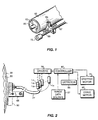
- FIGS. 1 and 2 A representative system is shown in FIGS. 1 and 2.
- the illustrated assembly includes a cylinder 50 around which is wrapped a lithographic plate blank 55; in accordance with the invention, cylinder 50 may be the plate cylinder of a printing press, or may instead be part of a stand-alone platesetter.
- Cylinder 50 includes a void segment 60, within which the outside margins of plate 55 are secured by conventional clamping means (not shown).
- the size of the void segment can vary greatly depending on the environment in which cylinder 50 is employed.
- cylinder 50 is straightforwardly incorporated into the design of a conventional lithographic press, and serves as the plate cylinder of the press.
- plate 55 receives ink from an ink train, whose terminal cylinder is in rolling engagement with cylinder 50.
- the latter cylinder also rotates in contact with a blanket cylinder, which transfers ink to the recording medium.
- the press may have more than one such printing assembly arranged in a linear array. Alternatively, a plurality of assemblies may be arranged about a large central impression cylinder in rolling engagement with all of the blanket cylinders.
- the recording medium is mounted to the surface of the. impression cylinder, and passes through the nip between that cylinder and each of the blanket cylinders.
- Suitable central-impression and in-line press configurations are described in U.S. Patent Nos. 5,163,368 and 4,911,075.
- Cylinder 50 is supported in a frame and rotated by a standard electric motor or other conventional means (illustrated schematically in FIG. 2).
- the angular position of cylinder 50 is monitored by a shaft encoder.
- a writing array 65 mounted for movement on a lead screw 67 and a guide bar 69, traverses plate 55 as it rotates.
- Axial movement of writing array 65 results from rotation of a stepper motor 72, which turns lead screw 67 and thereby shifts the axial position of writing array 55.
- Stepper motor 72 is activated during the time writing array - 65 is positioned over void 60, after writing array 65 has passed over the entire surface of plate 55. The rotation of stepper motor 72 shifts writing array 65 to the appropriate axial location to begin the next imaging pass.
- the axial index distance between successive imaging passes is determined by the number of imaging elements in writing array 65 and their configuration therein, as well as by the desired resolution.
- a series of laser sources L 1 , 1 2 , L 3 ... L n driven by suitable laser drivers collectively designated by reference numeral 75, each provide output to a fiber-optic cable.
- the lasers are preferably gallium-arsenide or other diode models, although any high-speed lasers that emit in the near infrared region can be utilized advantageously.
- the final plates should be capable of delivering at least 1,000, and preferably at least 50,000 printing impressions. This requires fabrication from durable material, and imposes certain minimum power requirements on the laser sources. Because the present invention avoids the need to ablate one or more plate layers, power levels can be relatively low and imaging speeds quite high; of course, because of the need to transfer a minimum quantity of energy to achieve the requisite heating effect, there remains a tradeoff between power and achievable speed. This is discussed in greater detail below.
- the cables that carry laser output are collected into a bundle 77 and emerge separately into writing array 65. It may prove desirable, in order to conserve power, to maintain the bundle in a configuration that does not require bending above the fiber's critical angle of refraction (thereby maintaining total internal reflection); however, we have not found this necessary for good performance.
- a controller 80 actuates laser drivers 75 when the associated lasers reach appropriate points opposite plate 55, and in addition operates stepper motor 72 and the cylinder drive motor 82.
- Laser drivers 75 should be capable of operating at high speed to facilitate imaging at commercially practical rates.
- the drivers preferably include a pulse circuit capable of generating at least 40,000 laser-driving pulses/second, with each pulse being relatively short, e.g., on the order of 1-5 ⁇ sec.
- Controller 80 receives data from two sources.
- the angular position of cylinder 50 with respect to writing array 65 is constantly monitored by a detector 85, which provides signals indicative of that position to controller 80.
- an image data source e.g., a computer
- the image data define points on plate 55 where image spots are to be written.
- Controller 80 therefore, correlates the instantaneous relative positions of writing array 65 and plate 55 (as reported by detector 85) with the image data to actuate the appropriate laser drivers at the appropriate times during scan of plate 55.
- the control circuitry required to implement this scheme is well-known in the scanner and plotter art; a suitable design is described in U.S. Patent No. 5,174,205.
- the laser output cables terminate in lens assemblies, mounted within writing array 65, that precisely focus the beams onto the surface of plate 55.
- Post-imaging cleaning can be accomplished using a contact cleaning device 90.
- a contact cleaning device 90 This may be, for example, a rotating brush or belt, or other suitable means; useful mechanical cleaning devices for on-press applications, which can be employed with or without a cleaning solvent (or non-solvent), are dsescribed in U.S. Patent Nos. 5,148,746 and 5,568,768 and copending application serial No. US-A-5,755,158.
- Cleaning device 90 may be associated with writing array 65 so as to traverse plate 55 therewith, or may instead be a separate assembly in proximity to plate 55, as shown in FIG. 2.
- FIG. 3 illustrates a construction 100 comprising a surface layer 102 and a substrate 104.
- Layers 102 and 104 exhibit opposite affinities for ink and/or an ink-abhesive fluid.
- surface layer 102 is a silicone polymer or fluoropolymer that repels ink
- substrate 104 is an oleophilic polyester or treated metal as described below; the result is a dry plate.
- surface layer 102 is a hydrophilic material such as polyvinyl alcohol, while substrate 104 is both oleophilic and hydrophobic (again, polymer films such as polyester are suitable).
- Substrate 104 is preferably strong, stable and flexible, and includes or is fabricated from a material that absorbs imaging radiation.
- substrate 104 may be a polyester or polycarbonate film containing carbon-black particles or other radiation absorber.
- Preferred organic materials include heat-stable polymers, e.g., phenyl-substituted siloxanes (typically phenylmethyldimethylsiloxane copolymers).
- an adhesion-promoting comonomer e.g., aminopropylmethylsiloxane
- Polyimides also represent a readily available class of heat-stable polymer.
- suitable absorbers include a wide range of dyes and pigments, such as phthalocyanines (e.g., aluminum phthalocyanine chloride, titanium oxide phthalocyanine, vanadium (IV) oxide phthalocyanine, and the soluble phthalocyanines supplied by Aldrich Chemical Co., Milwaukee, WI); naphthalocyanines (see, e.g. , U.S. Patent Nos.
- phthalocyanines e.g., aluminum phthalocyanine chloride, titanium oxide phthalocyanine, vanadium (IV) oxide phthalocyanine, and the soluble phthalocyanines supplied by Aldrich Chemical Co., Milwaukee, WI
- naphthalocyanines see, e.g. , U.S. Patent Nos.
- metal substrate shown at 115 in FIG. 4
- metals rapidly conduct heat and therefore ordinarily serve as poor heating layers
- a black, mixed-valence iron oxide can be produced on a ferrous metal. The oxide will absorb IR radiation, and the color can be deepened (and radiation absorption thereby enhanced) through doping with a metal such as manganese.
- color can be imparted to a metal substrate through anodizing.
- This process converts the surface of an aluminum substrate to aluminum oxide by employing the substrate as the anode of an electrolytic cell, and can be utilized to apply color in several ways.
- organic dyes can be absorbed in the pores of the anodic coatings, or mineral pigments can be precipitated within the pores, before the coating is sealed. The depth of dye absorption (and, therefore, the degree of radiation absorption) depends on the thickness and porosity of the anodic coating.
- integral color anodizing pigmentation is caused during anodizing by the occlusion of microparticles in the coating, which result from the anodic reaction of the electrolyte with the microconstituents and matrix of the aluminum alloy.
- the aluminum is conventionally anodized in a sulfuric acid electrolyte, after which it is rinsed and transferred to an acidic electrolyte containing a dissolved metal salt.
- a metallic pigment is electrodeposited in the pores of the anodic coating.
- tin, nickel or cobalt is deposited, and the resulting bronze or black colors provide good absorption of, for example, near-IR radiation. See, e.g. , Aluminum and Aluminum Alloys , J.R. Davis, ed. (ASM International 1993).
- a metal sheet can be laminated to substrate 104.
- Suitable metals, laminating procedures and preferred dimensions and operating conditions are all described in the '032 patent, and can be straightforwardly applied to the present context without undue experimentation.
- FIG. 3 illustrates the consequences of exposing the plate 100 to the output of an imaging laser.
- an imaging pulse P having a Gaussian spatial profile as indicated
- reaches plate 100 it passes through layer 102 and heats layer 104, causing formation of a gas bubble or pocket 108. Expansion of pocket 108 lifts layer 102 off layer 104 in the region of the imaging pulse.
- surface layer 102 is substantially transparent to imaging radiation, and is formulated to resist reattachment to layer 104 following dissipation of gas pocket 108.
- layer 102 is chemically formulated to undergo rapid thermal homolysis (pyrolysis) in response to the heat applied to the underside of layer 102 by energy-absorbing layer 104.
- layer 102 may be (or include as a primary polymer component) a silicone block copolymer having a chemically labile species as one of the blocks.
- the silicone block copolymer has an ABA structure, where the A blocks are long, functionally (e.g., vinyldimethyl) terminated polysiloxane chains and the B block is an acrylic (e.g., a short polymethylmethacrylate chain).
- a suitable chemical formula is:
- layer 102 is a hydrophilic polymer such as polyvinyl alcohol (e.g., the Airvol 125 or 165 material supplied by Air Products, Allentown, PA).
- polyvinyl alcohol e.g., the Airvol 125 or 165 material supplied by Air Products, Allentown, PA.
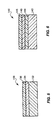
- the plate construction 110 includes a substrate 115, a surface layer 117, and an intermediate layer 120 that irreversibly detaches either from layer 115 or layer 117 in response to an imaging pulse.
- post-imaging cleaning removes layers 117 and 120 where plate 110 is struck by imaging pulses, while in the latter case, layer 120 remains and serves as a printing surface.
- Layer 120 may be, for example, a polymeric material capable of evolving nitrogen gas upon heating; suitable examples are disclosed in U.S. Patent No. 5,278,023.
- the plate is a three-layer construction as shown in FIG. 5.
- the plate 130 includes includes a substrate 132, a layer 134 capable of absorbing imaging radiation, and a surface coating layer 136.
- Layer 134 may be polymeric or metal in nature. In the former case, layer 134 can, for example, consist of a polymeric system that intrinsically absorbs in the near-IR region (e.g., a polypyrrole), or a polymeric coating into which near IR-absorbing components have been dispersed or dissolved (e.g., a solvent-cast polyimide or poly(amide-imide) containing an absorbing pigment as described above).
- layer 134 can be at least one layer of a metal deposited onto a polyester substrate 132.
- brief exposure of this construction to a laser pulse heats the thin metal layer without ablating it, detaching it from the overlying layer 136 and destroying its anchorage.
- cleaning can either remove this layer in its entirety along with detached portions of overlying layer 136, or can instead leave layer 134 either in whole or in part.
- metals typically retain applied ink (in the case of a dry plate) or fountain solution (in the case of a negative-working wet plate having a hydrophobic, oleophilic surface), it is often unnecessary to achieve complete removal in any case.
- layer 134 is preferably thin to minimize heat transport within layer 134 (i.e., transverse to the direction of the imaging pulse), thereby concentrating heat within the region of the imaging pulse so as to effect formation of a gas pocket at minimal imaging power.
- layer 134 is titanium applied (e.g., by sputtering or vacuum deposition) at 300 ⁇ 50 ⁇ or less.
- Titanium is preferred for layer 134, particularly in conjunction with a silicone layer 136. Titanium layers exhibit substantial resistance to handling damage, particularly when compared with metals such as aluminum, zinc and chromium; this feature is important both to production, where damage to layer 134 can occur prior to coating thereover of layer 136, and in the printing process itself where weak intermediate layers can reduce plate life. In the case of dry lithography, titanium further enhances plate life through resistance to interaction with ink-borne solvents that, over time, migrate through layer 136; other materials, such as organic layers, may exhibit permeability to such solvents and allow plate degradation.
- silicone coatings applied to titanium layers tend to cure at faster rates and at lower temperatures (thereby avoiding thermal damage to substrate 132), require lower catalyst levels (thereby improving pot life) and, in the case of addition-cure silicones, exhibit "post-cure" cross-linking (in marked contrast, for example, to nickel, which can actually inhibit the initial cure).
- post-cure cross-linking in marked contrast, for example, to nickel, which can actually inhibit the initial cure.
- the latter property further enhances plate life, since more fully cured silicones exhibit superior durability, and also provides further resistance against ink-borne solvent migration.
- Post-cure cross-linking is also useful where the desire for high-speed coating (or the need to run at reduced temperatures to avoid thermal damage to substrate 132) make full cure on the coating apparatus impracticable.
- Titanium also provides advantageous environmental and safety characteristics: its ablation does not produce measurable emission of gaseous byproducts, and environmental exposure presents minimal health concerns.
- titanium like many other metals, exhibits some tendency to interact with oxygen during the deposition process (vacuum evaporation, electron-beam evaporation or sputtering); however, the lower oxides of titanium most likely to be formed in this manner (particularly TiO) are strong absorbers of near-IR imaging radiation. In contrast, the likely oxides of aluminum, zinc and bismuth are relatively poor absorbers of such radiation.
- metals for layer 134 are adhesion to layers 132, 136, and the absence of deleterious interference with layer 136 when applied in a pre-cured state; for example, some metals may poison the catalyst used to cure layer 136. These criteria support the use of metals such as aluminum, vanadium and zirconium.
- layer 134 may be a metallic inorganic layer.
- metallic inorganic material may comprise a compound of at least one metal with at least one non-metal, or a mixture of such compounds. If, as is preferred, this layer is to serve as a printing surface (i.e., persist despite cleaning), it is typically applied at a thickness of several hundred ⁇ or more.
- the metal component of a suitable metallic inorganic material may be a d-block (transition) metal, an f-block (lanthanide) metal, aluminum, indium or tin, or a mixture of any of the foregoing (an alloy or, in cases in which a more definite composition exists, an intermetallic).
- Preferred metals include titanium, zirconium, vanadium, niobium, tantalum, molybdenum and tungsten.
- the non-metal component may be one or more of the p-block elements boron, carbon, nitrogen, oxygen and silicon.
- a metal/non-metal compound in accordance herewith may or may not have a definite stoichiometry, and may in some cases (e.g., Al-Si compounds) be an alloy.
- Preferred metal/non-metal combinations include TiN, TiON, TiO x (where 0.9 ⁇ x ⁇ 2.0), TiAlN, TiAlCN, TiC and TiCN.
- Preferred materials for substrate 132 have surfaces to which the deposited metal adheres well, and exhibit substantial flexibility to facilitate spooling and winding over the surface of a plate cylinder.
- One useful class of preferred polyester material is the unmodified film exemplified by the MELINEX 442 product marketed by ICI Films, Wilmington, DE, and the 3930 film product marketed by Hoechst-Celanese, Greer, SC.
- polyester materials that have been modified to enhance surface adhesion characteristics as described above. Suitable polyesters of this type include the ICI MELINEX 453 film. These materials accept titanium without the loss of properties.
- Other metals by contrast, may require custom pretreatments of the polyester film in order to create compatibility therebetween. For example, vinylidenedichloride-based polymers are frequently used to anchor aluminum onto polyesters.
- a preferred film thickness is 0.007 inch, but thinner and thicker versions can be used effectively.
- a preferred thickness is 0.002 inch.
- substrates capable of reflecting any unabsorbed imaging radiation back into layer 134 may be useful to employ substrates capable of reflecting any unabsorbed imaging radiation back into layer 134. Suitable for this purpose in the context of IR imaging radiation is the white 329 polyester film supplied by ICI Films, Wilmington, DE, which utilizes IR-reflective barium sulfate as the white pigment.
- substrate 132 may be transparent and reflectivity provided by the laminated support or the laminating adhesive ( see, e.g. , U.S. Patent No. 5,570,636).
- the plate 140 includes a substrate 142 and a surface layer 146 as discussed in connection with plate 130 (see FIG. 5); a polymeric absorbing layer 144, as discussed in connection with plate 110 (see FIG. 4); and an intermediate layer, also as discussed in connection with plate 110.
Landscapes
- Physics & Mathematics (AREA)
- Optics & Photonics (AREA)
- Thermal Sciences (AREA)
- Engineering & Computer Science (AREA)
- Manufacturing & Machinery (AREA)
- Printing Plates And Materials Therefor (AREA)
- Manufacture Or Reproduction Of Printing Formes (AREA)
Claims (26)
- Verfahren zum Belichten eines Flachdruckelementvorläufers (100, 110) ohne wesentliches Abschmelzen darin, wobei das Verfahren die folgenden Schritte aufweist:a. Bereitstellen eines Druckelementvorläufers (100, 110) mit einer obersten ersten Schicht (102, 117) und einer direkt unter der ersten Schicht (102, 117) liegenden und daran befestigten zweiten Schicht (104, 120), wobei die erste und die zweite Schicht (104, 120) unterschiedliche Affinitäten zu mindestens einer Druckflüssigkeit aufweisen, die aus der Gruppe ausgewählt ist, die aus Druckfarbe und einem farbabweisenden Fluid besteht;b. Erwärmen des Druckelementvorläufers (100, 110), um die erste Schicht (102, 117) in einer bildartigen Struktur irreversibel von der zweiten Schicht (104, 120) abzulösen [ohne die zweite Schicht (104, 120) wesentlich abzuschmelzen]; undc. Entfernen der ersten Schicht (102, 117) an den Stellen, wo sie von der zweiten Schicht (104, 120) abgelöst wurde, um ein lithographisches Bild zu erzeugen.
- Verfahren nach Anspruch 1, wobei die zweite Schicht (104, 120) ein behandeltes Metall ist, das unter Umständen keine Phasenänderung als Folge der Erwärmung erfährt.
- Verfahren nach Anspruch 1, wobei der Druckelementvorläufer (110) ferner eine unter der zweiten Schicht (120) angeordnete dritte Schicht (115) aufweist.
- Verfahren nach Anspruch 3, wobei die erste (117) und die dritte Schicht (115) unterschiedliche Affinitäten zu mindestens einer Druckflüssigkeit aufweisen, die aus der Gruppe ausgewählt ist, die aus Druckfarbe und einem farbabweisenden Fluid besteht, wobei der Entfernungsschritt ferner das Entfernen der zweiten Schicht (120) sowie der ersten Schicht (117) aufweist, wobei die erste Schicht (117) von der zweiten Schicht (120) abgelöst ist.
- Verfahren nach Anspruch 2, wobei die Metallschicht eine dunkle Oberfläche aufweist, die aus der Gruppe ausgewählt ist, die aus Oxiden, Carbiden und Nitriden besteht.
- Verfahren nach Anspruch 1, wobei die zweite Schicht ein oleophiles Polymer ist, möglicherweise ein leitfähiges Polycarbonat, das ein Mittel zur Absorption von Belichtungsstrahlung aufweist.
- Verfahren nach Anspruch 1, wobei die erste Schicht oleophob ist und Silicon aufweisen kann, und wobei die zweite Schicht Druckfarbe annimmt.
- Verfahren nach Anspruch 1, wobei die erste Schicht hydrophil und die zweite Schicht hydrophob und oleophil ist.
- Verfahren zum Belichten eines Flachdruckelementvorläufers (130, 140), wobei das Verfahren die folgenden Schritte aufweist:a. Bereitstellen eines Druckelementvorläufers (130, 140) mit einer obersten ersten Schicht (136, 146), einer unter der ersten Schicht (136, 146) angeordneten und daran befestigten zweiten Schicht (134, 144) und einer unter der zweiten Schicht (134, 144) angeordneten dritten Schicht (132, 142), wobei die erste und mindestens eine der anderen Schichten unterschiedliche Affinitäten zu mindestens einer Druckflüssigkeit aufweisen, die aus der Gruppe ausgewählt ist, die aus Druckfarbe und einem farbabweisenden Fluid besteht;b. Erwärmen des Druckelementvorläufers (130, 140), um die erste Schicht (136, 146) in einer bildarkigen Struktur irreversibel von der zweiten Schicht (134, 144) abzulösen, ohne die zweite Schicht (134, 144) abzuschmelzen; undc. Entfernen der ersten Schicht (136, 146) an den Stellen, wo sie von der zweiten Schicht (134, 144) abgelöst wurde, um ein lithographisches Bild zu erzeugen, das Bereiche mit den unterschiedlichen Affinitäten aufweist.
- Verfahren nach Anspruch 9, wobei der Entfernungsschritt außerdem das Entfernen der zweiten Schicht sowie der ersten Schicht an den Stellen aufweist, wo die erste Schicht von der zweiten Schicht abgelöst ist.
- Verfahren nach Anspruch 9, wobei die zweite Schicht ein Polymer oder ein Metall ist, wobei die Metallschicht unter Umständena. keine Phasenänderung als Folge der Erwärmung erfährt; oderb. mindestens eines der Metalle Titan, Aluminium, Vanadium und Zirconium aufweist.
- Verfahren nach Anspruch 1 oder Anspruch 9, wobei der Erwärmungsschritt aufweist:a. Anordnen mindestens einer Laserquelle (L1 - Ln), die Strahlung im nahen IR emittieren kann (können), die eine Belichtungsausgangsstrahlung erzeugen kann, in Abständen gegenüber dem Druckelementvorläufer (100, 110, 130, 140);b. Lenken der Ausgangsstrahlung mindestens einer Laserquelle (L1 - Ln), um sie auf den Druckelementvorläufer (100, 110, 130, 140) zu fokussieren;c. Herbeiführen einer Relativbewegung zwischen der Laserausgangsstrahlung und dem Druckelementvorläufer (100, 110, 130, 140), um eine Abtastung des Druckelementvorläufers (100, 110, 130, 140) durch die Laserausgangsstrahlung zu bewirken; undd. bildartige Belichtung des Druckelementvorläufers (100, 110, 130, 140) mit der Laserausgangsstrahlung im Verlauf der Abtastung.
- Verfahren nach Anspruch 9, wobei die erste Schicht im wesentlichen durchlässig für die Belichtungsausgangsstrahlung ist.
- Verfahren nach Anspruch 9, wobei die erste Schicht oleophob ist und Silicon aufweisen kann, und wobei die dritte Schicht oleophil ist.
- Verfahren nach Anspruch 14, wobei die erste Schicht (102, 117, 136, 146) Silicon aufweist.
- Verfahren nach Anspruch 9, wobei die zweite Schicht (104, 120) (134, 144) an Stellen, wo die erste Schicht (102, 117) (136, 146) von der zweiten Schicht (104, 120, 134, 144) abgelöst ist, zumindest teilweise nicht entfernt wird, wobei die erste Schicht (102, 117, 136, 146) oleophob ist und die zweite Schicht (104, 120, 134, 144) Druckfarbe annimmt.
- Verfahren nach Anspruch 9, wobei die erste Schicht (102, 117) (136, 146) hydrophil und die dritte Schicht (115, 132, 142) hydrophob und oleophil ist.
- Verfahren nach Anspruch 1 oder Anspruch 9, wobei die erste Schicht (102, 117) (136, 146) ein wärmeempfindliches Polymer aufweist, das bei Erwärmung chemisch modifiziert wird, um der Wiederbefestigung zu widerstehen.
- Verfahren nach Anspruch 18, wobei die erste Schicht (102, 117) (136, 146) ein wärmeempfindliches Polymer aufweist, das eine schnelle thermische Homolyse erfährt.
- Verfahren nach Anspruch 19, wobei die erste Schicht (102, 117) (136, 146) ein Blockcopolymer ist, das eine chemische Polysiloxan-Spezies und eine chemische Acryl-Spezies aufweist.
- Verfahren nach Anspruch 19, wobei der Druckelementvorläufer (140) ferner eine Zwischenschicht (148) zwischen der ersten und der zweiten Schicht aufweist und die irreversible Ablösung durch Ablösen der zweiten Schicht (144) von der Zwischenschicht erzielt wird.
- Druckplattenbelichtungsvorrichtung, die aufweist:a. eine Trägereinrichtung für einen Druckelementvorläufer (130, 140) mit einer obersten ersten Schicht (136, 146), einer unter der ersten Schicht (130, 140) angeordneten metallischen zweiten Schicht (134, 144) und einer unter der zweiten Schicht (134, 144) angeordneten dritten Schicht (132, 142), wobei die erste und die dritte Schicht unterschiedliche Affinitäten zu mindestens einer Druckflüssigkeit aufweisen, die aus der Gruppe ausgewählt ist, die aus Druckfarbe und einem farbabweisenden Fluid besteht; undb. eine Einrichtung zum Erwärmen des Druckelementvorläufers (130, 140), um die erste Schicht (136, 146) in einer bildartigen Struktur von der Metallschicht abzulösen, ohne die Metallschicht abzuschmelzen, wodurch das Entfernen zumindest der ersten Schicht (136, 146) an den Stellen, wo sie von der zweiten Schicht (134, 144) abgelöst ist, erleichtert wird, um ein lithographisches Bild zu erzeugen.
- Druckplattenbelichtungsvorrichtung, die aufweist:a. eine Trägereinrichtung für einen Druckelementvorläufer (100, 110) (130) mit einer obersten ersten Schicht (102, 117, 136) und einer direkt unter der ersten Schicht liegenden und daran befestigten zweiten Schicht (104, 120, 134), wobei die erste und die zweite Schicht unterschiedliche Affinitäten zu mindestens einer Druckflüssigkeit aufweisen, die aus der Gruppe ausgewählt ist, die aus Druckfarbe und einem farbabweisenden Fluid besteht; undb. eine Einrichtung zum Erwärmen des Druckelementvorläufers (100, 110, 130), um die erste Schicht (102, 117, 136) in einer bildartigen Struktur von der zweiten Schicht (104, 120) (134) ohne wesentliches Abschmelzen abzulösen, wodurch das Entfernen der ersten Schicht (102, 117, 136) an den Stellen, wo sie von der zweiten Schicht (104, 120, 134) abgelöst ist, erleichtert wird, um ein lithographisches Bild zu erzeugen.
- Vorrichtung nach Anspruch 23, die ferner eine Einrichtung aufweist, um zumindest die erste Schicht (102, 117, 136) an den Stellen zu entfernen, wo sie von der zweiten Schicht (104, 120) (134) abgelöst ist, um ein lithographisches Bild zu erzeugen.
- Vorrichtung nach Anspruch 23, wobei die Erwärmungseinrichtung mindestens einen Schnellbelichtungslaser mit niedriger Leistung aufweist.
- Vorrichtung nach Anspruch 23, die ferner aufweist:a. eine Einrichtung zum Lenken der Ausgangsstrahluag von dem mindestens einen Laser (L1 - Ln), um sie auf den an der Trägereinrichtung befestigten Druckelementvorläufer (100, 110, 130) zu fokussieren;b. eine Einrichtung zum Herbeiführen einer Relativbewegung zwischen der Ausgangsstrahlung und dem Druckelementvorläufer (100, 110, 130), um eine Abtastung des Druckelementvorläufers (100, 110, 130) durch die Laserausgangsstrahlung zu bewirken; undc. eine Einrichtung zum Ansteuern des mindestens einen Lasers (L1 - Ln) in einer bildartigen Struktur im Verlauf der Abtastung.
Applications Claiming Priority (3)
| Application Number | Priority Date | Filing Date | Title |
|---|---|---|---|
| US08/851,205 US6107001A (en) | 1997-05-05 | 1997-05-05 | Method and apparatus for non-ablative, heat-activated lithographic imaging |
| US851205 | 1997-05-05 | ||
| PCT/US1998/007837 WO1998050231A1 (en) | 1997-05-05 | 1998-04-14 | Method and apparatus for non-ablative, heat-activated lithographic imaging |
Publications (2)
| Publication Number | Publication Date |
|---|---|
| EP0981441A1 EP0981441A1 (de) | 2000-03-01 |
| EP0981441B1 true EP0981441B1 (de) | 2003-05-02 |
Family
ID=25310222
Family Applications (1)
| Application Number | Title | Priority Date | Filing Date |
|---|---|---|---|
| EP98918407A Expired - Lifetime EP0981441B1 (de) | 1997-05-05 | 1998-04-14 | Methode und verfahren zur bebilderung von flachdruckplatten durch wärme ohne ablation |
Country Status (7)
| Country | Link |
|---|---|
| US (1) | US6107001A (de) |
| EP (1) | EP0981441B1 (de) |
| JP (1) | JP3433948B2 (de) |
| AU (1) | AU728903B2 (de) |
| CA (1) | CA2289214C (de) |
| DE (1) | DE69814064T2 (de) |
| WO (1) | WO1998050231A1 (de) |
Families Citing this family (23)
| Publication number | Priority date | Publication date | Assignee | Title |
|---|---|---|---|---|
| US6085656A (en) * | 1998-07-24 | 2000-07-11 | Presstak, Inc. | Method of lithographic imaging with reduced debris-generated performance degradation and related constructions |
| EP0993945B1 (de) * | 1998-10-15 | 2004-05-06 | Agfa-Gevaert | Im Wärmeverfahren arbeitendes Aufzeichnungsmaterial zur Herstellung von Druckplatten, welche kein Anfeuchtwasser benötigen |
| US6387591B1 (en) | 1998-10-15 | 2002-05-14 | Agfa-Gevaert | Heat-mode driographic printing plate precursor |
| JP2000296682A (ja) | 1999-04-15 | 2000-10-24 | Fuji Photo Film Co Ltd | 平版印刷版の製造方法 |
| US6374738B1 (en) * | 2000-05-03 | 2002-04-23 | Presstek, Inc. | Lithographic imaging with non-ablative wet printing members |
| US6378432B1 (en) * | 2000-05-03 | 2002-04-30 | Presstek, Inc. | Lithographic imaging with metal-based, non-ablative wet printing members |
| CN1273291C (zh) * | 2001-03-01 | 2006-09-06 | 压缩技术公司 | 平版印刷部件和使平版印刷部件成像的方法 |
| US6770416B2 (en) | 2001-07-26 | 2004-08-03 | Creo Il Ltd. | Multi-purpose modular infra-red ablatable graphic arts tool |
| JP2003279824A (ja) * | 2002-03-22 | 2003-10-02 | Fuji Photo Optical Co Ltd | 光学装置用機構部品 |
| AU2003249552A1 (en) * | 2002-08-07 | 2004-02-25 | Vim Technologies Ltd. | Lithographic printing members and a method and a system for preparation of lithographic printing members |
| US6720130B1 (en) * | 2002-10-08 | 2004-04-13 | Kodak Polychrome Graphics Llc | Radiation sensitive lithographic printing plate precursors having ablation-free imageable composition and method |
| JP3902125B2 (ja) * | 2002-12-03 | 2007-04-04 | 東京エレクトロン株式会社 | 温度測定方法及びプラズマ処理装置 |
| US20040239006A1 (en) * | 2003-01-22 | 2004-12-02 | Microfabrica Inc. | Silicone compositions, methods of making, and uses thereof |
| JPWO2006123549A1 (ja) * | 2005-05-19 | 2008-12-25 | コニカミノルタエムジー株式会社 | 画像形成方法および平版印刷版材料 |
| US20070090732A1 (en) * | 2005-10-25 | 2007-04-26 | The Charles Stark Draper Laboratory, Inc. | Systems, methods and devices relating to actuatably moveable machines |
| US7566582B2 (en) * | 2005-10-25 | 2009-07-28 | The Charles Stark Draper Laboratory, Inc. | Systems, methods and devices relating to actuatably moveable machines |
| FR2901888B1 (fr) * | 2006-05-30 | 2008-08-22 | Alessandro Manneschi | Portique detecteur de metaux comportant des moyens indicateurs perfectionnes |
| US8198010B2 (en) * | 2007-11-09 | 2012-06-12 | Presstek, Inc. | Lithographic imaging with printing members having hydrophilic, surfactant-containing top layers |
| JP5174134B2 (ja) * | 2010-11-29 | 2013-04-03 | 富士フイルム株式会社 | レーザー彫刻用樹脂組成物、レーザー彫刻用レリーフ印刷版原版、レリーフ印刷版の製版方法及びレリーフ印刷版 |
| KR102764369B1 (ko) | 2020-05-15 | 2025-02-07 | 삼성전자주식회사 | 기판 디본딩 장치 |
| US20250334453A1 (en) * | 2022-06-08 | 2025-10-30 | Sony Group Corporation | Thermal detection element, method of manufacturing thermal detection element, and image sensor |
| EP4674636A1 (de) | 2023-02-27 | 2026-01-07 | Toray Industries, Inc. | Direktziehender wasserfreier flachdruckplattenvorläufer und verfahren zur herstellung einer wasserfreien flachdruckplatte daraus |
| CN118683218B (zh) * | 2024-07-15 | 2026-01-30 | 清华大学 | 一种高效率图案化的限域印刷方法 |
Citations (1)
| Publication number | Priority date | Publication date | Assignee | Title |
|---|---|---|---|---|
| US5378580A (en) * | 1992-06-05 | 1995-01-03 | Agfa-Gevaert, N.V. | Heat mode recording material and method for producing driographic printing plates |
Family Cites Families (14)
| Publication number | Priority date | Publication date | Assignee | Title |
|---|---|---|---|---|
| FR1473751A (fr) * | 1965-04-03 | 1967-03-17 | Fuji Photo Film Co Ltd | Procédé de reproduction d'images |
| CA1144418A (en) * | 1979-12-17 | 1983-04-12 | Ari Aviram | Erosion process for generation of offset masters |
| US5256506A (en) * | 1990-10-04 | 1993-10-26 | Graphics Technology International Inc. | Ablation-transfer imaging/recording |
| AU674518B2 (en) * | 1992-07-20 | 1997-01-02 | Presstek, Inc. | Lithographic printing plates for use with laser-discharge imaging apparatus |
| US5351617A (en) * | 1992-07-20 | 1994-10-04 | Presstek, Inc. | Method for laser-discharge imaging a printing plate |
| US5339737B1 (en) * | 1992-07-20 | 1997-06-10 | Presstek Inc | Lithographic printing plates for use with laser-discharge imaging apparatus |
| US5278023A (en) * | 1992-11-16 | 1994-01-11 | Minnesota Mining And Manufacturing Company | Propellant-containing thermal transfer donor elements |
| DE69218951T2 (de) * | 1992-12-08 | 1997-11-06 | Agfa Gevaert Nv | Wärmeempfindliches Aufzeignungselement |
| US5608429A (en) * | 1993-08-02 | 1997-03-04 | Nippon Kayaku Kabushiki Kaisha | Laser marking method, laser marking composition and articles having color developing layer made of said composition |
| US5354633A (en) * | 1993-09-22 | 1994-10-11 | Presstek, Inc. | Laser imageable photomask constructions |
| US5517359A (en) * | 1995-01-23 | 1996-05-14 | Gelbart; Daniel | Apparatus for imaging light from a laser diode onto a multi-channel linear light valve |
| US5570636A (en) * | 1995-05-04 | 1996-11-05 | Presstek, Inc. | Laser-imageable lithographic printing members with dimensionally stable base supports |
| US5783364A (en) * | 1996-08-20 | 1998-07-21 | Presstek, Inc. | Thin-film imaging recording constructions incorporating metallic inorganic layers and optical interference structures |
| US5965326A (en) * | 1997-01-21 | 1999-10-12 | Presstek, Inc. | Method for selectively deleting undesired ink-receptive areas on wet lithographic printing constructions incorporating metallic inorganic layers |
-
1997
- 1997-05-05 US US08/851,205 patent/US6107001A/en not_active Expired - Lifetime
-
1998
- 1998-04-14 JP JP54810898A patent/JP3433948B2/ja not_active Expired - Fee Related
- 1998-04-14 EP EP98918407A patent/EP0981441B1/de not_active Expired - Lifetime
- 1998-04-14 WO PCT/US1998/007837 patent/WO1998050231A1/en not_active Ceased
- 1998-04-14 CA CA002289214A patent/CA2289214C/en not_active Expired - Fee Related
- 1998-04-14 DE DE69814064T patent/DE69814064T2/de not_active Expired - Lifetime
- 1998-04-14 AU AU71334/98A patent/AU728903B2/en not_active Ceased
Patent Citations (1)
| Publication number | Priority date | Publication date | Assignee | Title |
|---|---|---|---|---|
| US5378580A (en) * | 1992-06-05 | 1995-01-03 | Agfa-Gevaert, N.V. | Heat mode recording material and method for producing driographic printing plates |
Also Published As
| Publication number | Publication date |
|---|---|
| CA2289214A1 (en) | 1998-11-12 |
| AU728903B2 (en) | 2001-01-18 |
| DE69814064D1 (de) | 2003-06-05 |
| EP0981441A1 (de) | 2000-03-01 |
| JP3433948B2 (ja) | 2003-08-04 |
| WO1998050231A1 (en) | 1998-11-12 |
| AU7133498A (en) | 1998-11-27 |
| JP2001523181A (ja) | 2001-11-20 |
| US6107001A (en) | 2000-08-22 |
| CA2289214C (en) | 2003-11-25 |
| DE69814064T2 (de) | 2004-03-11 |
Similar Documents
| Publication | Publication Date | Title |
|---|---|---|
| US6107001A (en) | Method and apparatus for non-ablative, heat-activated lithographic imaging | |
| EP0684133B1 (de) | Flachdruckplatten zur Bebilderung mittels Laserbestrahlung | |
| JP3045899B2 (ja) | レーザ放電イメージング装置について用いるためのリソグラフ印刷プレート | |
| EP0689096B1 (de) | Lithographische Druckplatten mit einer oleophilen bilderzeugenden Schicht | |
| CA2319125C (en) | Laser-imageable printing members for wet lithographic printing | |
| JP3492616B2 (ja) | 赤外線レーザイメージング可能な平版印刷部材及びかかる印刷部材を調製し且つイメージングする方法 | |
| CA2128911C (en) | Lithographic printing members having secondary ablation layers for use with laser-discharge imaging apparatus | |
| US6465152B1 (en) | Imaging member containing heat sensitive thiosulfate polymer on improved substrate and methods of use | |
| EP0969967B1 (de) | Direktbeschreibbares wasserfrei arbeitendes bebilderbareselement mit verbesserten ablationseigenschaften, bebilderungsverfahren und druckverfahren | |
| JPH06186750A (ja) | レーザ放電イメージング方法及び装置 | |
| EP1151859A2 (de) | Lithographische Bebilderung mit auf Metallbasis, nicht-ablativer Nassflachdruckplatte | |
| EP1278633B1 (de) | Lithographische bilderzeugung mit druckelementen, die mehrphasige laserempfindliche schichte enthalten |
Legal Events
| Date | Code | Title | Description |
|---|---|---|---|
| PUAI | Public reference made under article 153(3) epc to a published international application that has entered the european phase |
Free format text: ORIGINAL CODE: 0009012 |
|
| 17P | Request for examination filed |
Effective date: 19991108 |
|
| AK | Designated contracting states |
Kind code of ref document: A1 Designated state(s): BE DE FR GB IT |
|
| 17Q | First examination report despatched |
Effective date: 20010914 |
|
| GRAH | Despatch of communication of intention to grant a patent |
Free format text: ORIGINAL CODE: EPIDOS IGRA |
|
| GRAH | Despatch of communication of intention to grant a patent |
Free format text: ORIGINAL CODE: EPIDOS IGRA |
|
| RAP1 | Party data changed (applicant data changed or rights of an application transferred) |
Owner name: PRESSTEK, INC. |
|
| GRAA | (expected) grant |
Free format text: ORIGINAL CODE: 0009210 |
|
| AK | Designated contracting states |
Designated state(s): BE DE FR GB IT |
|
| REG | Reference to a national code |
Ref country code: GB Ref legal event code: FG4D |
|
| REF | Corresponds to: |
Ref document number: 69814064 Country of ref document: DE Date of ref document: 20030605 Kind code of ref document: P |
|
| ET | Fr: translation filed | ||
| PLBE | No opposition filed within time limit |
Free format text: ORIGINAL CODE: 0009261 |
|
| STAA | Information on the status of an ep patent application or granted ep patent |
Free format text: STATUS: NO OPPOSITION FILED WITHIN TIME LIMIT |
|
| 26N | No opposition filed |
Effective date: 20040203 |
|
| PGFP | Annual fee paid to national office [announced via postgrant information from national office to epo] |
Ref country code: IT Payment date: 20090929 Year of fee payment: 12 |
|
| PG25 | Lapsed in a contracting state [announced via postgrant information from national office to epo] |
Ref country code: IT Free format text: LAPSE BECAUSE OF NON-PAYMENT OF DUE FEES Effective date: 20100414 |
|
| PGFP | Annual fee paid to national office [announced via postgrant information from national office to epo] |
Ref country code: BE Payment date: 20120426 Year of fee payment: 15 |
|
| PGFP | Annual fee paid to national office [announced via postgrant information from national office to epo] |
Ref country code: FR Payment date: 20120503 Year of fee payment: 15 |
|
| PGFP | Annual fee paid to national office [announced via postgrant information from national office to epo] |
Ref country code: DE Payment date: 20130429 Year of fee payment: 16 Ref country code: GB Payment date: 20130429 Year of fee payment: 16 |
|
| BERE | Be: lapsed |
Owner name: *PRESSTEK INC. Effective date: 20130430 |
|
| PG25 | Lapsed in a contracting state [announced via postgrant information from national office to epo] |
Ref country code: BE Free format text: LAPSE BECAUSE OF NON-PAYMENT OF DUE FEES Effective date: 20130430 |
|
| REG | Reference to a national code |
Ref country code: FR Ref legal event code: ST Effective date: 20131231 |
|
| PG25 | Lapsed in a contracting state [announced via postgrant information from national office to epo] |
Ref country code: FR Free format text: LAPSE BECAUSE OF NON-PAYMENT OF DUE FEES Effective date: 20130430 |
|
| REG | Reference to a national code |
Ref country code: DE Ref legal event code: R119 Ref document number: 69814064 Country of ref document: DE |
|
| GBPC | Gb: european patent ceased through non-payment of renewal fee |
Effective date: 20140414 |
|
| REG | Reference to a national code |
Ref country code: DE Ref legal event code: R119 Ref document number: 69814064 Country of ref document: DE Effective date: 20141101 |
|
| PG25 | Lapsed in a contracting state [announced via postgrant information from national office to epo] |
Ref country code: DE Free format text: LAPSE BECAUSE OF NON-PAYMENT OF DUE FEES Effective date: 20141101 Ref country code: GB Free format text: LAPSE BECAUSE OF NON-PAYMENT OF DUE FEES Effective date: 20140414 |