EP0981457B1 - Antriebsvorrichtung für ein zwischen endstellungen bewegbares teil eines fahrzeugs und verfahren zu ihrer herstellung - Google Patents
Antriebsvorrichtung für ein zwischen endstellungen bewegbares teil eines fahrzeugs und verfahren zu ihrer herstellung Download PDFInfo
- Publication number
- EP0981457B1 EP0981457B1 EP98959778A EP98959778A EP0981457B1 EP 0981457 B1 EP0981457 B1 EP 0981457B1 EP 98959778 A EP98959778 A EP 98959778A EP 98959778 A EP98959778 A EP 98959778A EP 0981457 B1 EP0981457 B1 EP 0981457B1
- Authority
- EP
- European Patent Office
- Prior art keywords
- drive device
- indexing wheel
- magnetized
- wheel
- vehicle
- Prior art date
- Legal status (The legal status is an assumption and is not a legal conclusion. Google has not performed a legal analysis and makes no representation as to the accuracy of the status listed.)
- Expired - Lifetime
Links
- 238000000034 method Methods 0.000 title claims description 7
- 238000004519 manufacturing process Methods 0.000 title claims description 4
- 230000005291 magnetic effect Effects 0.000 claims description 10
- 238000009434 installation Methods 0.000 claims description 4
- 239000000463 material Substances 0.000 claims description 4
- 230000004907 flux Effects 0.000 claims description 3
- 238000010276 construction Methods 0.000 claims description 2
- 239000000470 constituent Substances 0.000 claims 1
- 230000005415 magnetization Effects 0.000 description 11
- 230000008901 benefit Effects 0.000 description 7
- 230000003287 optical effect Effects 0.000 description 4
- 230000005540 biological transmission Effects 0.000 description 3
- 230000009467 reduction Effects 0.000 description 3
- 229920001169 thermoplastic Polymers 0.000 description 3
- 239000004416 thermosoftening plastic Substances 0.000 description 3
- 238000001514 detection method Methods 0.000 description 2
- 238000006073 displacement reaction Methods 0.000 description 2
- 230000000694 effects Effects 0.000 description 2
- 238000011156 evaluation Methods 0.000 description 2
- 238000003780 insertion Methods 0.000 description 2
- 230000037431 insertion Effects 0.000 description 2
- 238000003860 storage Methods 0.000 description 2
- 229910000639 Spring steel Inorganic materials 0.000 description 1
- 238000004026 adhesive bonding Methods 0.000 description 1
- 230000000712 assembly Effects 0.000 description 1
- 238000000429 assembly Methods 0.000 description 1
- 210000000078 claw Anatomy 0.000 description 1
- 230000001419 dependent effect Effects 0.000 description 1
- 230000007274 generation of a signal involved in cell-cell signaling Effects 0.000 description 1
- 239000003292 glue Substances 0.000 description 1
- 238000002347 injection Methods 0.000 description 1
- 239000007924 injection Substances 0.000 description 1
- 239000002991 molded plastic Substances 0.000 description 1
- 230000007935 neutral effect Effects 0.000 description 1
- 239000000843 powder Substances 0.000 description 1
- 230000008569 process Effects 0.000 description 1
- 238000005476 soldering Methods 0.000 description 1
- 230000001360 synchronised effect Effects 0.000 description 1
- 238000009423 ventilation Methods 0.000 description 1
Images

Classifications
-
- B—PERFORMING OPERATIONS; TRANSPORTING
- B60—VEHICLES IN GENERAL
- B60J—WINDOWS, WINDSCREENS, NON-FIXED ROOFS, DOORS, OR SIMILAR DEVICES FOR VEHICLES; REMOVABLE EXTERNAL PROTECTIVE COVERINGS SPECIALLY ADAPTED FOR VEHICLES
- B60J7/00—Non-fixed roofs; Roofs with movable panels, e.g. rotary sunroofs
- B60J7/02—Non-fixed roofs; Roofs with movable panels, e.g. rotary sunroofs of sliding type, e.g. comprising guide shoes
- B60J7/04—Non-fixed roofs; Roofs with movable panels, e.g. rotary sunroofs of sliding type, e.g. comprising guide shoes with rigid plate-like element or elements, e.g. open roofs with harmonica-type folding rigid panels
- B60J7/057—Driving or actuating arrangements e.g. manually operated levers or knobs
-
- B—PERFORMING OPERATIONS; TRANSPORTING
- B60—VEHICLES IN GENERAL
- B60J—WINDOWS, WINDSCREENS, NON-FIXED ROOFS, DOORS, OR SIMILAR DEVICES FOR VEHICLES; REMOVABLE EXTERNAL PROTECTIVE COVERINGS SPECIALLY ADAPTED FOR VEHICLES
- B60J7/00—Non-fixed roofs; Roofs with movable panels, e.g. rotary sunroofs
- B60J7/02—Non-fixed roofs; Roofs with movable panels, e.g. rotary sunroofs of sliding type, e.g. comprising guide shoes
- B60J7/04—Non-fixed roofs; Roofs with movable panels, e.g. rotary sunroofs of sliding type, e.g. comprising guide shoes with rigid plate-like element or elements, e.g. open roofs with harmonica-type folding rigid panels
- B60J7/057—Driving or actuating arrangements e.g. manually operated levers or knobs
- B60J7/0573—Driving or actuating arrangements e.g. manually operated levers or knobs power driven arrangements, e.g. electrical
-
- H—ELECTRICITY
- H02—GENERATION; CONVERSION OR DISTRIBUTION OF ELECTRIC POWER
- H02K—DYNAMO-ELECTRIC MACHINES
- H02K29/00—Motors or generators having non-mechanical commutating devices, e.g. discharge tubes or semiconductor devices
- H02K29/06—Motors or generators having non-mechanical commutating devices, e.g. discharge tubes or semiconductor devices with position sensing devices
- H02K29/08—Motors or generators having non-mechanical commutating devices, e.g. discharge tubes or semiconductor devices with position sensing devices using magnetic effect devices, e.g. Hall-plates, magneto-resistors
-
- H—ELECTRICITY
- H02—GENERATION; CONVERSION OR DISTRIBUTION OF ELECTRIC POWER
- H02K—DYNAMO-ELECTRIC MACHINES
- H02K7/00—Arrangements for handling mechanical energy structurally associated with dynamo-electric machines, e.g. structural association with mechanical driving motors or auxiliary dynamo-electric machines
- H02K7/10—Structural association with clutches, brakes, gears, pulleys or mechanical starters
- H02K7/116—Structural association with clutches, brakes, gears, pulleys or mechanical starters with gears
- H02K7/1163—Structural association with clutches, brakes, gears, pulleys or mechanical starters with gears where at least two gears have non-parallel axes without having orbital motion
- H02K7/1166—Structural association with clutches, brakes, gears, pulleys or mechanical starters with gears where at least two gears have non-parallel axes without having orbital motion comprising worm and worm-wheel
-
- E—FIXED CONSTRUCTIONS
- E05—LOCKS; KEYS; WINDOW OR DOOR FITTINGS; SAFES
- E05Y—INDEXING SCHEME ASSOCIATED WITH SUBCLASSES E05D AND E05F, RELATING TO CONSTRUCTION ELEMENTS, ELECTRIC CONTROL, POWER SUPPLY, POWER SIGNAL OR TRANSMISSION, USER INTERFACES, MOUNTING OR COUPLING, DETAILS, ACCESSORIES, AUXILIARY OPERATIONS NOT OTHERWISE PROVIDED FOR, APPLICATION THEREOF
- E05Y2400/00—Electronic control; Electrical power; Power supply; Power or signal transmission; User interfaces
- E05Y2400/10—Electronic control
- E05Y2400/32—Position control, detection or monitoring
- E05Y2400/322—Position control, detection or monitoring by using absolute position sensors
- E05Y2400/326—Position control, detection or monitoring by using absolute position sensors of the angular type
Definitions
- the invention is based on a drive device the genus of claim 1 or a method according to Genus of claim 4 or 5.
- the publication DE 10 24 373 C3 is already one Drive device for an between end positions Movable part known as the sunroof of a vehicle.
- This drive device has an electric motor the reduction gear downstream of the electric motor, one pulley coupled to the reduction gear for Moving a rope leading to the sunroof and one Switching device that by means of a gear pair
- the ones from Switch fingers actuable switch contacts are used for The electric motor stops when the sunroof is in reaches its constructive end positions.
- US 44,68,063 A is another Drive device for a sunroof known.
- This contains an electric motor, a worm gear, a Safety clutch on the worm gear, a gear shaft and a first driven by the gear shaft Gear arrangement for driving a pinion into which Engage sunroof drive wires, and a second Gear arrangement for driving a switching device.
- the second gear arrangement is here as a so-called Eccentric gear transmission designed and registered Ratchet wheel with cams.
- the first gear arrangement and the second gear arrangement designed such that at a sliding roof between his two End positions the ratchet wheel makes less than one turn.
- the ratchet wheel has two cams at axial intervals, which are each assigned a microswitch.
- Such a code disk is here with a Gray code equipped, therefore requires several code tracks and sets a relatively complicated evaluation circuit, which to the optical sensors is connected in advance as well Control circuit, the evaluation results with from one Compare program memory readable setpoints and in Depending on the comparison result, the speed of the Electric motor controls.
- One by the pamphlet EP 0 531 793 A1 known further drive device with a so-called operable in two directions Ultrasonic motor also has one in sync with one Wiper arm rotatable code disc, the light-dark markings having.
- the light-dark markings arranged so that it is directly connected to an optical sensor Specify swivel positions of the wiper arm.
- An electrical positioning drive is known from EP 0 692 400 A1, at the radially successive different tracks for angle detection are arranged.
- permanent magnets are such in mechanical grooves Switching wheels arranged that these in the radial inner surfaces with sensor elements interact.
- the paths and angle settings are structurally fixed.
- WO 97/43602 A shows a device for detecting rotary movements, at which the radial outer surfaces of a magnetic ring via pole shoes with a detector interact.
- the magnetic areas are also structurally fixed.
- control devices indifferent whether their ratchet wheels synchronized with output shafts from Drive devices are rotated or indirectly via reduction gears with fixed Gear ratios from these output shafts mechanically driven, sometimes mechanically are to be adapted for each vehicle type predefined paths or angles between the end positions of the movable parts and optionally at least one Intermediate position.
- the drive device according to the invention with the characterizing features of claim 1 and the method with the characterizing features of claim 4 or 5 has the advantage that the ratchet as a neutral component made of magnetizable material can be placed in stock and only shortly before installation in the respective individual Drive device or after installation in this Drive device can be manufactured by magnetizing with a magnetization pattern that matches that Use case corresponds.
- the ratchet wheels are each depending on the application on one or more concentric Ring zones have at least one north-south pole sequence. That I assigned magnetic field sensitive sensors such as Hall sensors easily according to a predetermined pattern and with great repeatability on one Have the holding device attached like the printed circuit board is a time-consuming adjustment of the control devices avoided. It is sufficient, for example, if a Cover the respective switching wheel for exact magnetization is checked by Northern Poland and Southern Poland. recognizable the invention reduces inventory costs and accelerates the completion of drive devices.
- process claim 4 give the advantage that the magnetization, for example an assembly line for such drive devices is feasible so that before commissioning one for it necessary magnetizing device only on that Insert the correct magnetizing coil or Magnetization tool.
- the magnetization on the assembly line avoids confusion and simplifies storage.
- the procedure with the characteristic features of the Claim 5 has the advantage that the washer on one Worm gear can be attached before this worm gear is installed in the drive device.
- control device of the drive device is suitable for stopping the electric motor for example in two end positions or / and additionally at least one intermediate position.
- the drive device with the characteristic features of claim 3 has the advantage that on the one hand Ratchet wheel non-rotatable with the drive device is coupled and on the other hand, for example disassembly restores the original Alignment is possible.
- the characteristic ones close Features a correct insertion of the ratchet wheel in the Drive device with a.
- the procedure with the characteristic features of the Claim 6 has the advantage that a one-time exact Rotational alignment of the magnetizing tool or the Magnetization coil a subsequent alignment of the Switching disc before final completion of the Makes drive device unnecessary. So far you could an unmagnetized switching disc in any desired Insert way in the drive device and non-rotatably fix, for example by gluing.
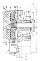
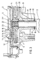
- the invention shows in Figure 1 a section through a partially completed drive device, Figure 2 a Item of the drive device according to the invention and Figure 3 shows the drive device according to the invention in assembled condition.
- Drive device 2 designed as a Drive device for a wiper, for the Partially drive the drive device 2 shown crank 3 of a not shown Crank gear, which leads to a wiper arm, in rotation added.
- the drive device 2 has a housing 4 and according to the Figure 3 shows a housing cover 5, not shown Electric motor for driving a worm shaft 6, one with the worm shaft 6 meshing worm wheel 7, one with the Worm wheel 7 non-rotatably connected worm wheel shaft 8, in the housing 4 bearing bushes 9 and 10 for the Worm gear shaft 8 and a control device 11 which in Example one connected to the worm wheel 7 in a rotationally fixed manner Ratchet wheel 12 and the front of the ratchet wheel 12 and there turned away from worm wheel 7 here three Magnetic flux sensitive sensors 13, 14, 15 on one Has sensor bridge 16.
- the sensor bridge 16 is designed, for example, as one Printed circuit board, which can be attached to the housing cover 5 can.
- the sensors 13, 14 and 15 do not point here soldering tabs shown, by means of which the sensors 13 can be soldered to 15 on the sensor bridge 16.
- the Sensors 13 to 15 are, for example, Hall sensors trained and have one of the switching disc 12 Minimum distance. So that this minimum distance is maintained, is a resilient outside of the housing 4 Axial locking ring 17 around the worm wheel shaft 8 arranged.
- the axial locking ring 17 has resilient Claws 18, which move the worm wheel shaft out 8 from the axial locking ring 17 and an approximation Avoid the worm wheel 7 to the sensors 13 to 15.
- a thrust washer 19 installed for example Spring steel sheet exists and has a wear-reducing effect, so that a constructively desired distance between the worm wheel 7 or the switching disk 12 and the sensors 13 to 15 remains sufficiently safe.
- Such wear-reducing measure is also taken through Inserting a second thrust washer 20 between a hub 21 of the worm wheel 7 and the housing 4.
- the worm wheel 7 and its hub 21 are made of thermoplastic Injection molded plastic, creating a twist-proof connection can be produced with the worm shaft 8 by arrangement a knurling 22 or an alternative cord in which to form a positive connection between the thermoplastic penetrates. So far are for responsible specialist the mechanical components of the Drive device 2 described sufficiently.
- FIG. 1 the ratchet 12 is cut longitudinally shown, it being apparent that a part 21 'of Hub 21 serves as a centering pin that fits into an opening 23 of the ratchet wheel 12 protrudes.
- a top view of that Switching wheel 12 with its opening 23 is shown in FIG. 2 shown.
- the circumference of the opening 23 interrupted by three uneven grooves 24, 25 and 26.
- the part 21 'can Cross sections of the grooves 24, 25 and 26 matched projections have, so that these projections together with the grooves 24, 25 and 26 form a multi-spline connection, which at Push the switching disc 12 over the part 21 ' Angle correct and also side correct alignment of the Switch disc 12 to the worm wheel 7 and thus later Crank 3 enforces insofar as with another Alignment of the ratchet 12 not over the part 21 ' is pluggable.
- the three grooves 24, 25 and 26 thus effect a coding, as for example in principle electrical connectors is known to avoid Incorrect connections and short circuits.
- a radial section show by the ratchet 12 is recognizable, that is Ratchet in the manner of a ring disc, so essentially thinly trained.
- This washer is for example made of permanent magnet powder and one thermoplastic bond. So that this washer 12 the your intended task of signal generation in at least one of the sensors 13 to 15 can meet, it is too magnetize, the magnetization depending on the adjustment range given by a vehicle type he follows. Depending on the vehicle type or even the body type hence the magnetization according to an adapted pattern respectively. An example of such a pattern is shown in Figure 2 by arranging a Magnetizing coil 30, so one Magnetizing tool, above the plan of the ring disc 12.
- the Magnetizing coil 30 Starting from a plus connection, the Magnetizing coil 30 successively radial Wire sections 31 to 39 and in between concentric, so arcuate wire sections 40 to 47. If Magnetizing current through the magnetizing coil 30 is conducted, this magnetizing current flows in the radial wire section 31 radially inwards, ie in the direction the center axis of the washer 12. This results in the "right screw rule" at 31 which there with N and S designated pole arrangement and at 32, 33, 34, 35, 36, 37 and 38, the pole arrangements given there result.
- the coil 30 can be fixed in a coil holder 50. On such a coil holder 50 is schematized in FIG. 1 shown.
- Ratchet 12 according to a predetermined pattern magnetize without the ratchet 12 with the Drive device 2 is combined. From this possibility is used, for example, when a unmagnetized blank of such a ratchet wheel from one Storage tank removed from the assembly line and on the Way to an assembly station of this assembly line is magnetized. In this case it is formed by the Arrangement of the grooves 24, 25 and 26 created the coding Ensure that the ratchet 12 only in the pre-planned Alignment along the part 21 'to the worm wheel 7 is lowerable. There it is then, for example, by means of Glue held.
- FIG. 1 The alternative to this is shown in FIG. 1 using which by means of a coil holder 50 above the Switch disk 12 aligned magnetizing coil 30. So that a predeterminable rotational orientation of the Magnetization pattern relative to the ratchet 12 and thereby the drive device 2 also comes about, that is Housing 4 of the drive device 2 in one Receiving device 51 used.
- the cradle 51 points for receiving one from the drive device 2 protruding section of the worm shaft 8 a Location bore 52 on and for the correct rotational alignment around the receiving bore 52, the housing 4 has one Alignment pin 53 which dips into an alignment groove 54, the itself at the top and at the front in one Receiving device 51 belonging column 55 is located.
- the invention is described in Connection with a drive device 2, for a Windshield wipers is determined and therefore relatively simple in Construction is.
- the invention is also applicable to a such drive device to the genus of Sunroof drive devices heard. This genus is extensively mentioned in the introduction to the description, so that it here no further explanation based on a drawing requirement.
- a Sunroof drive device does not matter in which way transmission torque transmission elements are trained. It also does not matter which type of gear for turning the ratchet wheel 12 depending the length of a path covered by a sunroof is used.
- the application of the invention is not to driving limited by windshield wipers or sunroofs. Rather, the invention can also be used with Window regulators, ventilation flaps, sliding doors, vehicle seats and steering wheel assemblies.
Landscapes
- Engineering & Computer Science (AREA)
- Power Engineering (AREA)
- Mechanical Engineering (AREA)
- Connection Of Motors, Electrical Generators, Mechanical Devices, And The Like (AREA)
- Transmission And Conversion Of Sensor Element Output (AREA)
- Gear Transmission (AREA)
- Power-Operated Mechanisms For Wings (AREA)
- Automobile Manufacture Line, Endless Track Vehicle, Trailer (AREA)
- Steering Controls (AREA)
- Control Of Position Or Direction (AREA)
Description
Claims (6)
- Antriebsvorrichtung (2) für ein zwischen Endstellungen bewegbares Teil eines Fahrzeugs mit einem Elektromotor, mit einer ein Drehmoment aus der Antriebsvorrichtung (2) herausführenden Welle (8), mit einer der Steuerung sowie Stillsetzen des Elektromotors für mindestens eine vorbestimmte Stellung des bewegbaren Teils dienenden Schalteinrichtung, die ein Schaltrad (12) mit mindestens einem Dauermagnet und mindestens einen magnetfeldempfindlichen Sensor (13, 14, 15) aufweist, wobei das Schaltrad (12) wenigstens mittelbar mit der Welle (8) verkoppelt ist, so daß es beim Bewegen des Teils des Fahrzeugs zwischen zwei Endstellungen höchstens um 360° drehbar ist, dadurch gekennzeichnet, daß das Schaltrad (12) scheibenförmig ausgebildet ist und wenigstens teilweise aus magnetisierbarem Werkstoff besteht, daß wenigstens ein magnetflußempfindlicher Sensor (13, 14, 15) mit einer Fläche des Schaltrads (12) wechselwirkt, die senkrecht zu einer Drehachse des Schaltrads (12) ausgerichtet ist, wobei wenigstens eine Ringzone der Fläche in wenigstens einem Bereich in Umlaufrichtung magnetisiert ist, daß das Schaltrad (12) in diesem Bereich der Ringzone im Umlaufsinn aufeinanderfolgend korrespondierende Magnetpole (N und S oder S und N) aufweist.
- Antriebsvorrichtung nach Anspruch 1, dadurch gekennzeichnet, daß radial versetzt das Schaltrad (12) wenigstens eine weitere magnetisierte Ringzone und dieser zugeordnet wenigstens einen weiteren magnetflußempfindlichen Sensor (13, 14, 15) aufweist.
- Antriebsvorrichtung nach Anspruch 1 oder 2, dadurch gekennzeichnet, daß das Schaltrad (12) von einer zentralen Öffnung (23) ausgehend mehrere unterschiedliche Nuten (24, 25, 26) aufweist, die Bestandteil einer Codierung sind, die einem lagerichtigen Einbau des Schaltrads (12) in die Antriebsvorrichtung (2) dient.
- Verfahren zum Herstellen einer Antriebsvorrichtung (2) mit einem Schaltrad (12) aus magnetisierbarem Werkstoff nach einem der Ansprüche 1 bis 3, dadurch gekennzeichnet, daß das Schaltrad (12) im wesentlichen unmittelbar vor dem Einbau in die Antriebsvorrichtung (2) nach einem vorgegebenen Muster magnetisiert wird.
- Verfahren zum Herstellen einer Antriebsvorrichtung (2) mit einem Schaltrad (12) aus magnetisierbarem Werkstoff nach einem der Ansprüche 1 bis 3, dadurch gekennzeichnet, daß das Schaltrad (12) in unmagnetisiertem Zustand in die Antriebsvorrichtung (2) eingebaut und darin befestigt wird und daß danach mittels einer Magnetisierungsvorrichtung (30, 50) das Schaltrad (12) nach einem vorgegebenen Muster magnetisiert wird.
- Verfahren nach einem der Ansprüche 4 oder 5, dadurch gekennzeichnet, daß das vorgegebene Muster in vorgegebener Weise mit in Drehrichtung verlaufender Magnetisierungsrichtung auf das Schaltrad (12) magnetisiert wird.
Applications Claiming Priority (3)
| Application Number | Priority Date | Filing Date | Title |
|---|---|---|---|
| DE19754843 | 1997-12-10 | ||
| DE19754843A DE19754843A1 (de) | 1997-12-10 | 1997-12-10 | Antriebsvorrichtung für ein zwischen Endstellungen bewegbares Teil eines Fahrzeugs und Verfahren zu ihrer Herstellung |
| PCT/DE1998/003175 WO1999029528A1 (de) | 1997-12-10 | 1998-10-30 | Antriebsvorrichtung für ein zwischen endstellungen bewegbares teil eines fahrzeugs und verfahren zu ihrer herstellung |
Publications (3)
| Publication Number | Publication Date |
|---|---|
| EP0981457A1 EP0981457A1 (de) | 2000-03-01 |
| EP0981457B1 true EP0981457B1 (de) | 2003-05-02 |
| EP0981457B2 EP0981457B2 (de) | 2006-05-03 |
Family
ID=7851421
Family Applications (1)
| Application Number | Title | Priority Date | Filing Date |
|---|---|---|---|
| EP98959778A Expired - Lifetime EP0981457B2 (de) | 1997-12-10 | 1998-10-30 | Antriebsvorrichtung für ein zwischen endstellungen bewegbares teil eines fahrzeugs und verfahren zu ihrer herstellung |
Country Status (7)
| Country | Link |
|---|---|
| US (1) | US6163125A (de) |
| EP (1) | EP0981457B2 (de) |
| JP (1) | JP2001515626A (de) |
| KR (1) | KR100570454B1 (de) |
| BR (1) | BR9807205A (de) |
| DE (2) | DE19754843A1 (de) |
| WO (1) | WO1999029528A1 (de) |
Cited By (1)
| Publication number | Priority date | Publication date | Assignee | Title |
|---|---|---|---|---|
| EP2378646A1 (de) | 2010-04-15 | 2011-10-19 | Brusa Elektronik AG | Verfahren und Einrichtung zur Magnetisierung permanent-erregter Synchronmaschinen sowie Rotor für solche Synchronmaschinen |
Families Citing this family (24)
| Publication number | Priority date | Publication date | Assignee | Title |
|---|---|---|---|---|
| DE19858630A1 (de) * | 1998-12-18 | 2000-06-21 | Bosch Gmbh Robert | Antriebsvorrichtung für ein verstellbares Teil eines Fahrzeugs |
| DE19937222C2 (de) * | 1999-08-06 | 2001-11-29 | Webasto Vehicle Sys Int Gmbh | Steuervorrichtung für einen Elektromotor für ein verstellbares Fahrzeugteil |
| FR2802032B1 (fr) * | 1999-11-18 | 2002-02-22 | Valeo Equip Electr Moteur | Machines electriques aptes a etre utilisees dans un vehicule automobile d'une part comme generateur et d'autre part comme moteur electrique pour le demarrage du moteur a combustion interne du vehicule |
| FR2807231B1 (fr) * | 1999-11-18 | 2002-06-07 | Valeo Equip Electr Moteur | Machines electriques aptes a etre utilisees dans un vehicule automobile d'une part comme generateur et d'autre part comme moteur electrique pour le demarrage du moteur a combustion interne du vehicule |
| DE10014735A1 (de) * | 2000-03-24 | 2001-10-11 | Bosch Gmbh Robert | Elektromotor insbesondere Wischermotor zum Wischen einer Scheibe eines Kraftfahrzeugs |
| DE10134937A1 (de) * | 2001-07-18 | 2003-02-06 | Bosch Gmbh Robert | Getriebe-Antriebseinheit mit Drehzahlerfassung |
| US7009386B2 (en) * | 2002-01-02 | 2006-03-07 | Stoneridge Control Devices, Inc. | Non-contact position sensor utilizing multiple sensor elements |
| JP2003344100A (ja) * | 2002-05-28 | 2003-12-03 | Niles Co Ltd | 回転検出装置及びその製造方法 |
| DE10258036B4 (de) * | 2002-12-12 | 2024-06-06 | Robert Bosch Gmbh | Elektromotor, insbesondere für eine Scheibenwischvorrichtung sowie Scheibenwischvorrichtung, insbesondere für ein Kraftfahrzeug |
| WO2004068679A1 (ja) * | 2003-01-27 | 2004-08-12 | Hitachi, Ltd. | コントローラ付き電動モータユニット |
| DE10313226A1 (de) * | 2003-03-25 | 2004-10-07 | Robert Bosch Gmbh | Elektrische Antriebseinheit |
| DE102005005802B3 (de) * | 2005-02-09 | 2006-06-14 | Hübner GmbH | Ausstellschiebetürsystem für ein Fahrzeug |
| SE528392C2 (sv) | 2005-03-11 | 2006-10-31 | Atlas Copco Rock Drills Ab | Givarinstallation i en växellåda för positionering |
| DE102005038050B4 (de) * | 2005-08-10 | 2009-09-24 | Küster Automotive Door Systems GmbH | Elektromotorisch betriebene Antriebseinheit für Kraftfahrzeuge |
| DE102005040647A1 (de) * | 2005-08-27 | 2007-03-08 | Valeo Systèmes d`Essuyage | Elektromotorischer Hilfsantrieb für Fahrzeuge |
| US8256161B2 (en) * | 2006-06-09 | 2012-09-04 | Mitsuba Corporation | Automatic opening/closing apparatus for vehicle |
| US7725231B2 (en) | 2006-09-11 | 2010-05-25 | Robert Bosch Gmbh | Method for displacing a movable part and sliding roof system for carrying out such a method |
| DE102008043214A1 (de) * | 2008-10-28 | 2010-04-29 | Zf Lenksysteme Gmbh | Lenkung |
| EP2325426B1 (de) * | 2009-11-20 | 2015-06-17 | Aisin Seiki Kabushiki Kaisha | Antriebsvorrichtung |
| US9073575B2 (en) * | 2010-05-12 | 2015-07-07 | GM Global Technology Operations LLC | Memory features for a manually adjustable apparatus |
| JP5600528B2 (ja) * | 2010-09-03 | 2014-10-01 | 株式会社東海理化電機製作所 | 回転角度検出装置 |
| KR101490952B1 (ko) * | 2013-12-23 | 2015-02-09 | 현대자동차 주식회사 | 회전체의 위치를 파악하는 장치 및 이를 이용한 와이퍼 작동 장치 |
| DE102018002158A1 (de) * | 2018-03-16 | 2019-09-19 | Paragon Ag | Sensorvorrichtung zur Erfassung einer Drehstellung einer Gelenkwelle von Karosseriekinematikvorrichtungen, z.B. von Spoilern |
| US11722036B2 (en) * | 2021-06-14 | 2023-08-08 | Commercial Vehicle Group, Inc. | Wiper motors and methods of manufacture and use thereof |
Family Cites Families (15)
| Publication number | Priority date | Publication date | Assignee | Title |
|---|---|---|---|---|
| US4508998A (en) † | 1981-02-09 | 1985-04-02 | David H. Rush | Brushless disc-type DC motor or generator |
| JPS5830830A (ja) * | 1981-08-13 | 1983-02-23 | Aisin Seiki Co Ltd | サンル−フ用駆動装置 |
| DE3829405A1 (de) † | 1988-08-30 | 1990-03-08 | Webasto Ag Fahrzeugtechnik | Betaetigungseinrichtung fuer elektromotorisch bewegbare teile von kraftfahrzeugen |
| US4866357A (en) * | 1988-12-19 | 1989-09-12 | Ford Motor Company | Windshield wiper and control system |
| US5200729A (en) † | 1989-08-29 | 1993-04-06 | Yamamoto Electric Corporation | Permanent magnet and magnetization apparatus for producing the permanent magnet |
| DE4021973C1 (de) * | 1990-07-10 | 1992-01-02 | Webasto Ag Fahrzeugtechnik, 8035 Stockdorf, De | |
| FR2670286B1 (fr) * | 1990-12-05 | 1993-03-26 | Moving Magnet Tech | Capteur magnetique de position et de vitesse a sonde de hall. |
| DE4130065C2 (de) * | 1991-09-11 | 1993-12-02 | Licentia Gmbh | Elektrischer Scheibenwischerantrieb |
| DE4424633A1 (de) * | 1994-07-13 | 1996-01-25 | Bosch Gmbh Robert | Elektrischer Positionsantrieb, insbesondere für Schiebedächer von Kraftfahrzeugen |
| JPH0861976A (ja) * | 1994-08-18 | 1996-03-08 | Asmo Co Ltd | 移動体の位置及び荷重検出装置 |
| JP3336141B2 (ja) * | 1995-01-27 | 2002-10-21 | アスモ株式会社 | 移動体の位置検出装置 |
| JP3007838B2 (ja) * | 1996-03-01 | 2000-02-07 | アスモ株式会社 | 移動体の位置検出装置および車両ドア |
| DE59711601D1 (de) * | 1996-05-11 | 2004-06-09 | Valeo Schalter & Sensoren Gmbh | Vorrichtung zum erfassen rotatorischer bewegungen |
| US6051899A (en) * | 1996-06-15 | 2000-04-18 | Itt Manufacturing Enterprises, Inc. | Drive mechanism |
| US5924324A (en) * | 1997-10-09 | 1999-07-20 | Ut Automotive Dearborn, Inc. | Movable gear drive windshield wiper |
-
1997
- 1997-12-10 DE DE19754843A patent/DE19754843A1/de not_active Withdrawn
-
1998
- 1998-10-30 BR BR9807205-6A patent/BR9807205A/pt not_active IP Right Cessation
- 1998-10-30 JP JP52961999A patent/JP2001515626A/ja active Pending
- 1998-10-30 KR KR1019997007178A patent/KR100570454B1/ko not_active Expired - Fee Related
- 1998-10-30 EP EP98959778A patent/EP0981457B2/de not_active Expired - Lifetime
- 1998-10-30 US US09/341,761 patent/US6163125A/en not_active Expired - Fee Related
- 1998-10-30 DE DE59808170T patent/DE59808170D1/de not_active Expired - Lifetime
- 1998-10-30 WO PCT/DE1998/003175 patent/WO1999029528A1/de not_active Ceased
Cited By (2)
| Publication number | Priority date | Publication date | Assignee | Title |
|---|---|---|---|---|
| EP2378646A1 (de) | 2010-04-15 | 2011-10-19 | Brusa Elektronik AG | Verfahren und Einrichtung zur Magnetisierung permanent-erregter Synchronmaschinen sowie Rotor für solche Synchronmaschinen |
| WO2011128842A2 (en) | 2010-04-15 | 2011-10-20 | Brusa Elektronik Ag | Method and device for the magnetization of magnetic material pieces of a rotor in a permanently excited synchronous machine, and rotor for such a synchronous machine |
Also Published As
| Publication number | Publication date |
|---|---|
| DE19754843A1 (de) | 1999-06-24 |
| EP0981457B2 (de) | 2006-05-03 |
| WO1999029528A1 (de) | 1999-06-17 |
| KR20000070913A (ko) | 2000-11-25 |
| JP2001515626A (ja) | 2001-09-18 |
| DE59808170D1 (de) | 2003-06-05 |
| EP0981457A1 (de) | 2000-03-01 |
| KR100570454B1 (ko) | 2006-04-13 |
| BR9807205A (pt) | 2000-05-23 |
| US6163125A (en) | 2000-12-19 |
Similar Documents
| Publication | Publication Date | Title |
|---|---|---|
| EP0981457B1 (de) | Antriebsvorrichtung für ein zwischen endstellungen bewegbares teil eines fahrzeugs und verfahren zu ihrer herstellung | |
| EP1660359B1 (de) | Antriebsvorrichtung für scheibenwischer mit einem parkstellungsschalter | |
| DE3730448C2 (de) | ||
| DE102015002562B4 (de) | Elektrische Maschine | |
| EP1070259B1 (de) | Drehungssensor | |
| WO1998040751A1 (de) | Motor mit drehzahlabgriff über einen hall-sensor | |
| DE112006002530T5 (de) | Scheibenwischeranordnung mit Direktantrieb | |
| EP1534565B1 (de) | Verfahren zum betreiben einer wischeranlage und wischeranlage | |
| DE9006935U1 (de) | Elektromotorischer Antrieb | |
| EP1042146B1 (de) | Scheibenwischer-antriebsvorrichtung | |
| DE102015017076A1 (de) | Elektrische Maschine, insbesondere Elektromotor für ein Kraftfahrzeug | |
| DE102005019854A1 (de) | Doppelscheibenwischersystem mit Kniehebelverbindung | |
| DE102005019853A1 (de) | Doppelscheibenwischersystem mit Direktantriebsmotor | |
| WO2016124416A1 (de) | Antriebseinheit für ein Wischersystem | |
| EP1114503B1 (de) | Kommutatormotor | |
| EP1312534A2 (de) | Vorrichtung zur Bestimmung des Lenkwinkels eines Lenkrades | |
| EP1057241B1 (de) | Antriebsvorrichtung für ein verstellbares teil eines fahrzeugs | |
| DE102019203482A1 (de) | Stirnrad und dessen Herstellverfahren sowie bürstenloser Elektromotor | |
| DE102005040646A1 (de) | Elektromotorischer Hilfsantrieb für Fahrzeuge | |
| DE10111400B4 (de) | Stellantrieb für Heizungs-, Lüftungs- oder Klimaklappen in einem Kraftfahrzeug | |
| EP1088952B1 (de) | Kraftfahrzeug-Türschloss | |
| DE19653208B4 (de) | Verfahren zur Herstellung eines permanenterregten niederpoligen Elektromotors mit einem hochpoligen Drehimpuls-Geber | |
| DE112010003114T5 (de) | Gleichstrom-Elektromotor, insbesondere für Bewegungen an Kraftfahrzeugen wieFensterheber, Sitzversteller, Scheibenwischer und dergleichen | |
| EP1037776B1 (de) | Scheibenwischvorrichtung | |
| DE10249845B4 (de) | Steuerungsvorrichtung für Fahrzeug-Dachsysteme |
Legal Events
| Date | Code | Title | Description |
|---|---|---|---|
| PUAI | Public reference made under article 153(3) epc to a published international application that has entered the european phase |
Free format text: ORIGINAL CODE: 0009012 |
|
| 17P | Request for examination filed |
Effective date: 19991217 |
|
| AK | Designated contracting states |
Kind code of ref document: A1 Designated state(s): DE ES FR GB IT |
|
| 17Q | First examination report despatched |
Effective date: 20020118 |
|
| GRAH | Despatch of communication of intention to grant a patent |
Free format text: ORIGINAL CODE: EPIDOS IGRA |
|
| GRAH | Despatch of communication of intention to grant a patent |
Free format text: ORIGINAL CODE: EPIDOS IGRA |
|
| GRAA | (expected) grant |
Free format text: ORIGINAL CODE: 0009210 |
|
| AK | Designated contracting states |
Designated state(s): DE ES FR GB IT |
|
| PG25 | Lapsed in a contracting state [announced via postgrant information from national office to epo] |
Ref country code: IT Free format text: LAPSE BECAUSE OF FAILURE TO SUBMIT A TRANSLATION OF THE DESCRIPTION OR TO PAY THE FEE WITHIN THE PRESCRIBED TIME-LIMIT;WARNING: LAPSES OF ITALIAN PATENTS WITH EFFECTIVE DATE BEFORE 2007 MAY HAVE OCCURRED AT ANY TIME BEFORE 2007. THE CORRECT EFFECTIVE DATE MAY BE DIFFERENT FROM THE ONE RECORDED. Effective date: 20030502 Ref country code: GB Free format text: LAPSE BECAUSE OF FAILURE TO SUBMIT A TRANSLATION OF THE DESCRIPTION OR TO PAY THE FEE WITHIN THE PRESCRIBED TIME-LIMIT Effective date: 20030502 |
|
| REG | Reference to a national code |
Ref country code: GB Ref legal event code: FG4D Free format text: NOT ENGLISH |
|
| REF | Corresponds to: |
Ref document number: 59808170 Country of ref document: DE Date of ref document: 20030605 Kind code of ref document: P |
|
| PG25 | Lapsed in a contracting state [announced via postgrant information from national office to epo] |
Ref country code: ES Free format text: LAPSE BECAUSE OF FAILURE TO SUBMIT A TRANSLATION OF THE DESCRIPTION OR TO PAY THE FEE WITHIN THE PRESCRIBED TIME-LIMIT Effective date: 20030813 |
|
| GBV | Gb: ep patent (uk) treated as always having been void in accordance with gb section 77(7)/1977 [no translation filed] |
Effective date: 20030502 |
|
| ET | Fr: translation filed | ||
| PLBQ | Unpublished change to opponent data |
Free format text: ORIGINAL CODE: EPIDOS OPPO |
|
| PLBI | Opposition filed |
Free format text: ORIGINAL CODE: 0009260 |
|
| PLAX | Notice of opposition and request to file observation + time limit sent |
Free format text: ORIGINAL CODE: EPIDOSNOBS2 |
|
| 26 | Opposition filed |
Opponent name: WEBASTO AG Effective date: 20040202 |
|
| PLBB | Reply of patent proprietor to notice(s) of opposition received |
Free format text: ORIGINAL CODE: EPIDOSNOBS3 |
|
| PUAH | Patent maintained in amended form |
Free format text: ORIGINAL CODE: 0009272 |
|
| STAA | Information on the status of an ep patent application or granted ep patent |
Free format text: STATUS: PATENT MAINTAINED AS AMENDED |
|
| 27A | Patent maintained in amended form |
Effective date: 20060503 |
|
| AK | Designated contracting states |
Kind code of ref document: B2 Designated state(s): DE ES FR GB IT |
|
| REG | Reference to a national code |
Ref country code: ES Ref legal event code: FD2A Effective date: 20031031 |
|
| ET3 | Fr: translation filed ** decision concerning opposition | ||
| PGFP | Annual fee paid to national office [announced via postgrant information from national office to epo] |
Ref country code: FR Payment date: 20131018 Year of fee payment: 16 |
|
| PGFP | Annual fee paid to national office [announced via postgrant information from national office to epo] |
Ref country code: DE Payment date: 20131217 Year of fee payment: 16 |
|
| REG | Reference to a national code |
Ref country code: DE Ref legal event code: R119 Ref document number: 59808170 Country of ref document: DE |
|
| PG25 | Lapsed in a contracting state [announced via postgrant information from national office to epo] |
Ref country code: DE Free format text: LAPSE BECAUSE OF NON-PAYMENT OF DUE FEES Effective date: 20150501 |
|
| REG | Reference to a national code |
Ref country code: FR Ref legal event code: ST Effective date: 20150630 |
|
| PG25 | Lapsed in a contracting state [announced via postgrant information from national office to epo] |
Ref country code: FR Free format text: LAPSE BECAUSE OF NON-PAYMENT OF DUE FEES Effective date: 20141031 |