EP0981674B1 - Schachtabdeckung - Google Patents
Schachtabdeckung Download PDFInfo
- Publication number
- EP0981674B1 EP0981674B1 EP98928253A EP98928253A EP0981674B1 EP 0981674 B1 EP0981674 B1 EP 0981674B1 EP 98928253 A EP98928253 A EP 98928253A EP 98928253 A EP98928253 A EP 98928253A EP 0981674 B1 EP0981674 B1 EP 0981674B1
- Authority
- EP
- European Patent Office
- Prior art keywords
- formed body
- manhole cover
- cover according
- manhole
- opening
- Prior art date
- Legal status (The legal status is an assumption and is not a legal conclusion. Google has not performed a legal analysis and makes no representation as to the accuracy of the status listed.)
- Expired - Lifetime
Links
- 230000008093 supporting effect Effects 0.000 claims abstract description 11
- 238000007789 sealing Methods 0.000 claims description 18
- 239000002184 metal Substances 0.000 claims description 13
- 229910052751 metal Inorganic materials 0.000 claims description 13
- 238000005266 casting Methods 0.000 claims description 7
- 239000002131 composite material Substances 0.000 claims description 7
- 239000004033 plastic Substances 0.000 claims description 5
- 229920003023 plastic Polymers 0.000 claims description 5
- 239000000463 material Substances 0.000 claims 2
- 230000002093 peripheral effect Effects 0.000 claims 2
- 230000002787 reinforcement Effects 0.000 claims 1
- 238000005728 strengthening Methods 0.000 claims 1
- 238000009434 installation Methods 0.000 abstract description 8
- 230000000694 effects Effects 0.000 description 3
- 230000007774 longterm Effects 0.000 description 3
- 229910001018 Cast iron Inorganic materials 0.000 description 2
- 230000006978 adaptation Effects 0.000 description 2
- 230000015572 biosynthetic process Effects 0.000 description 2
- 238000010276 construction Methods 0.000 description 2
- 238000006073 displacement reaction Methods 0.000 description 2
- 239000011152 fibreglass Substances 0.000 description 2
- 239000007788 liquid Substances 0.000 description 2
- 238000004519 manufacturing process Methods 0.000 description 2
- 239000000853 adhesive Substances 0.000 description 1
- 230000001070 adhesive effect Effects 0.000 description 1
- 230000002411 adverse Effects 0.000 description 1
- 239000010426 asphalt Substances 0.000 description 1
- 239000003638 chemical reducing agent Substances 0.000 description 1
- 238000003780 insertion Methods 0.000 description 1
- 230000037431 insertion Effects 0.000 description 1
- 238000007689 inspection Methods 0.000 description 1
- 230000000149 penetrating effect Effects 0.000 description 1
- 238000007665 sagging Methods 0.000 description 1
- 239000004576 sand Substances 0.000 description 1
- 239000010865 sewage Substances 0.000 description 1
- 239000002689 soil Substances 0.000 description 1
- 230000000087 stabilizing effect Effects 0.000 description 1
Images






Classifications
-
- E—FIXED CONSTRUCTIONS
- E02—HYDRAULIC ENGINEERING; FOUNDATIONS; SOIL SHIFTING
- E02D—FOUNDATIONS; EXCAVATIONS; EMBANKMENTS; UNDERGROUND OR UNDERWATER STRUCTURES
- E02D29/00—Independent underground or underwater structures; Retaining walls
- E02D29/12—Manhole shafts; Other inspection or access chambers; Accessories therefor
Definitions
- the invention relates to a manhole cover for in particular sewer shafts or the like provided in driving areas, according to the preamble of claim 1.
- Such a manhole cover is from NL-A-6 502 680 known.
- Known manhole covers especially in driving areas planned sewage structures, such as inlet shafts, inspection shafts or the like, consist of an inside Cover part receiving concrete ring, the outside in corresponding Base layers and / or pavement of the driving surface is. High pressure loads from vehicle tires or Like. Can move the concrete ring from its Lead installation position, so that adverse road damage the result are.
- the invention addresses the problem of a manhole cover for sewer shafts provided in particular in driving areas or the like.
- the components with low Technical effort towards the running surface is long-term stable are supported and in the upper part of the shaft part Enable long-term sealing.
- the manhole cover according to the invention is compared with one Extended support and covering contours to known concrete rings having molded body designed such that caused in the area of the sewer shaft of vehicles Pressure loads absorbed and damage caused by vertical and / or horizontal displacements of the components can be avoided.
- the upper one is in the plane of the Ring area of the molded body extending over the driving surface is minimized so that this only offers a small pressure application area.
- the one on the outer circumference is expanded on the bottom Supporting contour of the molded body integrated in the roadway structure, so that a wide wing forming on the ground Ring edge area is effective and with this both sagging and shifts of components avoided as well as unwanted Extensions in the upper joint area largely excluded are.
- the outside support contour of the molded body engages under the upper surface on the driving surface in the installed position, e.g. an asphalt layer, a paving or the like. So that close in this vulnerable wing area the shaft component has reached an additional support.
- the molded body In the area of its passage opening, the molded body is with the Profile attachment part designed so that it telescopically in the interior of the chess part is insertable and thus one Height-variable plug connection enables.
- the Profile attachment part designed so that it telescopically in the interior of the chess part is insertable and thus one Height-variable plug connection enables.
- respective elastic sealing rings are provided so that the components In the vertically and horizontally flexible installation position also small Can accommodate shifts without overloading and the shaft cover overall fluid-tight connection areas having.
- the molded body can be in a largely arbitrary design an insert part cast into the concrete, for example made of metal, plastic and / or in the form of a rubber body, as a composite casting can be made so that with low technical effort a quick adaptation to customer-specific different manhole covers is possible.
- the quality of the cast concrete is different Strength requirements can be met in such a way that the extended Profile attachment part in the area of the passage opening and the support contour the molded body is adapted to high loads and the Components of the manhole cover have a high long-term stability exhibit.
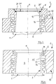
- Fig. 1 is a generally designated 1 and as an annular Concrete part provided molded body for a in Fig. 5th shaft cover 2 illustrated in principle, the cover part 5 having a passage opening 3 above a shaft part 4 running vertically to a driving surface 8 closes.
- the cover part 5 is in the molded body 1 via a upper support edge 6 and at the same time includes the Passage opening 3 of the molded body 1 has an upper region 7 of the Manhole part 4 in the manner of a plug connection.
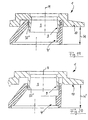
- the molded body 1 according to the invention is in the range of Passage opening 3 provided extension part 9 and on the outer circumference, the molded body 1 has an enlarged base Support contour 10 on (Fig. 1).
- the molded body 1 has in the area of the profile attachment part 9, on the one hand, the passage opening 3 delimiting and on the other hand forming an annular gap 12 Pipe part 13 with which one after assembly of the individual parts Type of telescopic connection, height-variable installation position (Fig. 2) is reached. 1, 2 and 3 and 13 to 20 shown
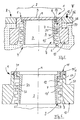
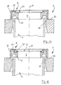
- Embodiments of the molded body 1 is the tubular part 13 made in one piece with the respective molded body 1 and in the further embodiments according to FIGS. 4 to 13 the pipe part of a pipe socket 13 'forming an individual part formed with an upper support ring 14, for example in upper area of the passage opening 3 of the molded body 1 on Support edge 6 can be hooked (Fig. 4).
- FIG. 4 and 5 is a first embodiment of a multi-part design of the shaft cover 2 forming Shown body 1, wherein after its positioning in Installation position of the pipe socket 13 'as an individual part in the illustrated Connection position can be inserted and thus the assembly of the manhole cover 2 is simplified overall.
- the manhole cover 2 shown the molded body 1 with the pipe socket 13 'over a Z-shaped cross section having intermediate ring 15 which is connected via variable dimensions of its support legs 17, 17 'an adjustment to different shaft parts 4.
- the intermediate ring 15 can be made of metal, e.g. Cast iron, exist or molded from plastic.
- the molded body 1 is above its support contour 10 into a further intermediate ring 16 divided so that the manhole cover 2 has four components, especially when installing large manhole covers with small Individual weights enable easy handling.
- 10 shows a further multi-part embodiment of the Shaped body 1 has a bottom-side support ring plate 17, the Shaped body 1 engages under the lower outer edge of the support contour 10 and so an advantageous enlargement of the support surface allows.
- the pipe socket 13 ' is in the region of its support ring 14 provided with an extension 18 that immediately rests on the top of the molded body 1.
- the pipe socket 13 ' can be formed from concrete or from metal, e.g. Cast iron, exist.
- the embodiment of the molded body 1 according to FIG. 9 shows this Training as a composite casting, being in a concrete structure 19 an insert part E forming an upper cover 20 in such a way is poured in that the molded body 1 is level with the Driving surface 8 has an upper edge protection.
- the composite casting formation of the molded body 1 according to FIG. 11 shows a further embodiment of the manhole cover 2, the inner pipe socket 13 'in the support position on one with a Cover part 20 'rests as insert part E connected ring plate 21, and this in turn via an outer ring body 22 is supported on the ground.
- the molded body 1 is similar 2 shaped, in the vicinity of the upper support edge 6th a cast-in metal ring 20 '' as edge protection the insert E forms.
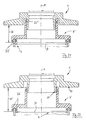
- the embodiments of the molded body provided as a composite casting 1 according to FIGS. 14 to 18 show further combinations of insert parts formed in particular from metal parts E in Connection position with the concrete structure.
- Fig. 14 that is Insert part E as a cover part 20 'via a web part 23
- the pipe part 13 '' consists of a Area of a support profile 24 with the molded body 1 in one piece cast metal semi-finished 25 and on the top this molded body 1, the cover part 20 'is also over Support profiles 24 'anchored.
- 16 is the tubular part 13 in its lower end with a stabilizing Metal attachment part 25 provided.
- the molded body 1 is in a practical embodiment as a Hollow cylinder body defining the central longitudinal plane M. It is also conceivable to have a polygonal circumferential contour or in an asymmetrical form (M '; Fig. 15) one To provide support contour 10 ', which is only over a partial area the circumferential contour extends.
- FIGS. 17 and 18 show one largely shortened pipe part 13 similar to FIG. 1, the respective Shaped body 1 have insert parts E above of the respective support contour 10 to the top of the molded body 2 down with different anchors 27 having metal cover parts 28 are provided.
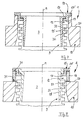
- FIG. 19 to 22 show the molded body 1 each with an essentially identical cross-sectional contour, wherein those shown in different support heights H, H ' Shaped body 1, the telescopic effect of the tube parts 13 when Illustrate installation.
- the shaft part 4 (Fig. 21) is a respective one as a reducer for the shaft diameter D formed adapter part 4 'is provided, the respective Sealing areas 32 '' and 33 '.
- the adapter part 4 ' 19 and 20 can be provided in the form of a shaft cone his.
- the molded body 1 or the respective one Additional components 15, 16, 22, 4 ' are these assembly components in their connection areas formed in the installed position in each case as a sealing ring 30 effective support parts 31 (Fig. 3) provided, which consist for example of rubber or metal and also according to the type of the composite casting in the cast concrete can be molded.
- the tube part 13 or the pipe socket 13 ', 13' ' in an advantageous embodiment on the to the annular gap 12 facing outer surface with a first Seal ring part 32 provided with a on the inside of the Support contour 10 provided second sealing ring part 33 cooperates so that the annular gap 12 both towards the passage opening 3 against liquid leakage as well as to the environment is sealed fluid-tight against the ingress of liquid.
- the formation of the pipe lugs 13 and 13 ' enables centering of the molded body 1 in its installed position and at the same time can in the area of the annular gap 12 component tolerances of Chess part 4 and / or molded body 12 are balanced so that a secure sealing system of the parts is reached.
- On his to Passage opening 3 directed inside has the support approach 10 a draft slope S, so that even with extreme displacements and / or inclined positions of the molded body 1 sharp-edged system with notch effect on the shaft part 4 avoided and their damage is largely excluded.
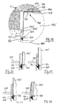
- the rubber sealing ring 30 is enlarged Detail illustration clarifies, with the associated wall 34 has a ring heel 35 so that its pressure effect on the sealing ring 30, a fluid-tight, annular system of Components causes.
- the installation position of paving stones forming the driving surface 8 36 illustrates the supporting effect of Support contour 10 in the region of a support shoulder 37 which on the Driving surface 8 acting pressure forces (arrow F) over a Intermediate layer 38 can accommodate so that road damage is avoided are.
- 23 to 33 is the multi-part design of the manhole cover illustrated in a further embodiment, wherein on the underside of the molded body 1, a tube part 113 or 113 ' (Fig. 28) is supported, which with different depths T, T ' (Similar to FIGS. 21, 22) engage in the manhole part 104, 104 ' can (Fig. 25, 26).
- a tube part 113 or 113 ' (Fig. 28) is supported, which with different depths T, T ' (Similar to FIGS. 21, 22) engage in the manhole part 104, 104 ' can (Fig. 25, 26).
- the tube part 113 is provided with an upper support ring surface 114 provided that in a pre-assembly position of the components with the Shaped body 1 over an adhesive connection K (Fig. 25) permanently can be connected.
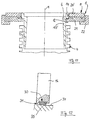
- 24, 26 to 29 are in one second embodiment several screw connections 115 as Detachable connection of the components provided, each one U-profile rails 116 (Fig. 23) over their legs 117, 118 narrowing downward opening slot a threaded sleeve 119 (Fig. 27) in the longitudinal direction of the rail 116 take up longitudinally.
- screws 120 penetrating in the support ring surface 114 the components are braced.
- the screw connection can be produced in the area of an elongated hole 121 be, in the area of a precise rotation of the components during assembly is possible.
- the U-shaped rails 116 are expediently in the molded body 1 cast in its manufacture (Fig. 27) and before one the sealing ring 122 inserted is a fluid-tight Connection of the molded body 1 made with the pipe part 113.
- This connection construction enables, for example also by moving the parts horizontally, a Adaptation of the shaped body 1 to the laying level of the paving 8.
- the shaft part 104 can also be made as one HD-PE existing plastic pipe. So that is the manhole cover with sufficient stability in the area the plug connection of pipe part 113, 113 'and shaft part 104,104 'with lower weight in a cheaper version produced.
- the exemplary embodiment according to FIGS. 28 to 33 shows a shaft part 104 ', which is provided as a cathedral shaft above a tank 123 is and consists of a metal tube.
- the pipe part 113 ' is in the area of its outer Provided lateral surface with a profile 124, in the Sealing ring 125 is set so that its lip part 126th during vertical insertion (arrow E, Fig. 28) of the pipe part 113 'forms a fluid-tight connection in the shaft part 104'.
- 30 to 33 show respective sectional representations several embodiments of the profiling 124 on the each the sealing ring 125 is fixed.
- An anchor part 127 is provided, by means of which one additional support for the shaft part 104 'to the surrounding Cover layer is formed.
- the layers of the bottom layer 130 can be used when installing the manhole part 104, 104 'up to its upper edge area advantageous be compressed so that after inserting the pipe part 113, 113 'this connection is free of pressure loads.
Landscapes
- Engineering & Computer Science (AREA)
- Environmental & Geological Engineering (AREA)
- Life Sciences & Earth Sciences (AREA)
- General Life Sciences & Earth Sciences (AREA)
- Mining & Mineral Resources (AREA)
- Paleontology (AREA)
- Civil Engineering (AREA)
- General Engineering & Computer Science (AREA)
- Structural Engineering (AREA)
- Sewage (AREA)
- Underground Structures, Protecting, Testing And Restoring Foundations (AREA)
- Flexible Shafts (AREA)
- Mechanical Pencils And Projecting And Retracting Systems Therefor, And Multi-System Writing Instruments (AREA)
Description
- Fig. 1
- eine Querschnittsdarstellung des erfindungsgemäßen Formkörpers als Einzelteil in einer ersten Ausführungsform,
- Fig. 2 und Fig. 3
- jeweilige Querschnittsdarstellungen ähnlich Fig. 1 mit dem ein Schachtteil übergreifenden Formkörper in Einbaulage,
- Fig. 4
- eine Querschnittsdarstellung des Formkörpers in zweiteiliger Ausführung mit einem die Durchlaßöffnung bildenden Rohrstutzen,
- Fig. 5
- eine Querschnittsdarstellung des in Einbaulage in einer Fahrfläche befindlichen Formkörpers in zweiteiliger Ausführung ähnlich Fig. 4,
- Fig. 6 bis Fig. 11
- jeweilige Querschnittsdarstellungen des als mehrteilige Baugruppe vorgesehenen Formkörpers in Verbindungsstellung mit dem Schachteil,
- Fig. 12
- eine vergrößerte Ausschnittsdarstellung eines Verbindungsbereiches der Montage-Baugruppe mit einem Dichtring,
- Fig. 13 bis Fig. 18
- jeweilige Ausführungsformen des Formkörpers als ein Verbundgußteil mit unterschiedlichen Einsatzteilen,
- Fig. 19 bis Fig. 22
- jeweilige einstückige Ausführungsformen des Formkörpers ähnlich Fig. 2 in Einbaulage mit einem zum Schachtteil gerichteten Adapterteil,
- Fig. 23
- eine Draufsicht der Schachtabdeckung gemäß einer Schnittlinie XXIII - XXIII in Fig. 24 mit das Rohrteil am Formkörper festlegenden Haltegliedern,
- Fig. 24 bis Fig. 26
- jeweilige Schnittdarstellungen der Schachtabdeckung gemäß einer Linie XXIV - XXIV in Fig. 23,
- Fig. 27
- eine vergrößerte Ausschnittdarstellung des Verbindungsbereiches von Formkörper und Rohrteil,
- Fig. 28
- eine Querschnittdarstellung ähnlich Fig. 24 mit der Schachtabdeckung im Bereich eines Domschachtes mit Rohrteil und Dichtung,
- Fig. 29
- eine vergrößerte Auschnittdarstellung der Verbindung von Formkörper und Rohrteil gemäß Fig. 28, und
- Fig. 30 bis Fig. 33
- jeweilige Auschnittsdarstellungen von Dichtungen im Stützbereich des Rohrteils am Schachtteil ähnlich Fig. 29.
Claims (21)
- Schachtabdeckung für insbesondere in Fahrflächen (8) vorgesehene Kanalisationsschächte oder dgl., bestehend aus einem als Betonring ausgebildeten Formkörper (1), der in Einbaulage auf einem oberen Stützrand (6) oberhalb einer Durchlaßöffnung (3) einen Deckelteil (5) aufnimmt, und unterhalb des Stützrandes (6) eine einen oberen Bereich (7) eines Schachtteils (4) aufnehmende Erweiterung der Durchlaßöffnung (3) aufweist, die zum Außenumfang des Formkörpers (1) hin an einem als erweiterte Stützkontur (10) in einer umgebenden Bodenschicht (38; 130) vorgesehenen Profilansatzteil (9) angrenzt, dadurch gekennzeichnet, daß der Formkörper (1) im inneren Bereich des Profilansatzteils (9) mit einem einerseits die Durchlaßöffnung (3) begrenzenden Rohrteil (13; 13'; 113; 113') versehen ist, das andererseits zur Stützkontur (10) hin einen Ringspalt (12) bildet, in den das Schachtteil (4) zumindest bereichsweise über eine Steckverbindung eingreift.
- Schachtabdeckung nach Anspruch 1, dadurch gekennzeichnet, daß der Formkörper (1) im Bereich des Profilansatzteiles (9) mit zumindest einem Dichtungsteil versehen ist.
- Schachtabdeckung nach Anspruche 1 oder 2, dadurch gekennzeichnet, daß der Formkörper (1) im Bereich seines Ringspaltes (12) einen vom Rohrteil (13) vorstehenden Dichtring (32) und/oder einen an der Innenseite der Stützkontur (10) vorgesehenen Dichtring (33) aufweist, derart, daß das Schachtteil (4) fluiddicht umfaßt ist.
- Schachtabdeckung nach einem der Ansprüche 1 bis 3, dadurch gekennzeichnet, daß der Formkörper (1) als ein Verbundgußteil ausgebildet ist, in dessen Betonstruktur zumindest ein Einsatzteil (E) aus Metall, Kunststoff, Gummi oder dgl. integriert ist.
- Schachtabdeckung nach einem der Ansprüche 1 bis 4, dadurch gekennzeichnet, daß der Rohrteil (13) einstückig mit dem Formkörper (1) geformt ist.
- Schachtabdeckung nach Anspruch 5, dadurch gekennzeichnet, daß der Rohrteil (13) mit einer sich konisch erweiternden Innenwandung und einer zylindrischen äußeren Mantelfläche die Durchlaßöffnung (3) bildet.
- Schachtabdeckung nach einem der Ansprüche 1 bis 6, dadurch gekennzeichnet, daß der Formkörper (1) in mehrteiliger Ausführung (13', 16) und/oder mit jeweiligen Zusatzbauteilen (15) eine Montageeinheit bildet.
- Schachtabdeckung nach einem der Anspruch 7, dadurch gekennzeichnet, daß als Rohrteil ein Einzelteil vorgesehen ist, das von einem im oberen Bereich der Durchlaßöffnung (3) des Formkörpers (1) einhängbaren Rohrstutzen (13') mit oberem Stützring (14) gebildet ist.
- Schachtabdeckung nach Anspruch 7 oder 8, dadurch gekennzeichnet, daß der Rohrstutzen (13') über einen als Z-förmiges Einzelteil vorgesehenen Zwischenring (15) am oberen Stützrand (6) des Formkörpers (1) abgestützt ist.
- Schachtabdeckung nach einem der Ansprüche 1 bis 9, dadurch gekennzeichnet, daß der Formkörper (1) im Bereich seiner zur Fahrfläche gerichteten Oberseite mit zumindest einer von dem Einsatzteil (E) gebildeten Schutzkante (20, 20', 20'') versehen ist.
- Schachtabdeckung nach einem der Ansprüche 1 bis 10, dadurch gekennzeichnet, daß der Formkörper (1 im Bereich seines oberen Stützrandes (6) ein als Dichtring (30) wirksames Auflageteil (31) aufweist.
- Schachtabdeckung nach einem der Ansprüche 1 bis 11, dadurch gekennzeichnet, daß an der Innenwandung des Rohrteiles (13) bzw. des Rohrstutzens (13') eine oder mehrere Trittstufen (38) und/oder ein Stützteil (38') für einen Schmutzfänger oder dgl. vorgesehen sind.
- Schachtabdeckung nach einem der Ansprüche 1 bis 12, dadurch gekennzeichnet, daß der in der Montage-Baugruppe vorgesehene Formkörper (1) in sämtlichen Stütz-Verbindungsbereichen zu Teilen der Baugruppe hin mit einem Dichtungsring (31) versehen ist.
- Schachtabdeckung nach einem der Ansprüche 1 bis 13, dadurch gekennzeichnet, daß der Formkörper (1) im Bereich seiner äußeren Stützkontur (10) eine zur Fahrfläche (8) gerichtete Auflageschulter (37) bildet.
- Schachtabdeckung nach einem der Ansprüche 1 bis 14, dadurch gekennzeichnet, daß der Formkörper (1) im Bereich seiner Stützkontur (10) eine den Ringspalt (12) erweiternde Formschräge (S) aufweist.
- Schachtabdeckung nach einem der Ansprüche 1 bis 16, dadurch gekennzeichnet, daß der Formkörper (1) in Einbaulage mit seiner Stützkontur (10) bodenseitig auf einem Ringkörper (17) aufliegt.
- Schachtabdeckung nach einem der Ansprüche 1 bis 16, dadurch gekennzeichnet, daß die im Formkörper (1) vorgesehenen Einsatzteile (E) eine Aussteifung nach Art einer Betonbewehrung bilden.
- Schachtabdeckung nach einem der Ansprüche 1 bis 17, dadurch gekennzeichnet, daß der Formkörper (1) eine kreisringförmige oder vieleckige Umfangskontur aufweist.
- Schachtabdeckung nach einem der Ansprüche 1 bis 18, dadurch gekennzeichnet, daß der Formkörper (1) eine sich über einen Teilbereich der Umfangskontur erstreckende Stützkontur (10') aufweist.
- Schachtabdeckung nach einem der Ansprüche 1 bis 19, dadurch gekennzeichnet,daß der Formkörper (1) über ein Adapterteil (4') mit dem Schachtteil (4) höhen- und/oder durchmesservariabel verbunden ist.
- Schachtabdeckung nach einem der Ansprüche 1 bis 20, dadurch gekennzeichnet, daß das dem Formkörper (1) zugeordnete Rohrteil (113; 113') aus Metall und/oder Kunststoff besteht und dieses am Formkörper (1) über eine Klebeverbindung (K) und/oder eine Schraubverbindung (115) festlegbar ist.
Priority Applications (1)
| Application Number | Priority Date | Filing Date | Title |
|---|---|---|---|
| SI9830258T SI0981674T1 (en) | 1997-05-15 | 1998-05-13 | Manhole cover |
Applications Claiming Priority (3)
| Application Number | Priority Date | Filing Date | Title |
|---|---|---|---|
| DE29708650U DE29708650U1 (de) | 1997-05-15 | 1997-05-15 | Schachtabdeckung |
| DE29708650U | 1997-05-15 | ||
| PCT/EP1998/002804 WO1998051870A1 (de) | 1997-05-15 | 1998-05-13 | Schachtabdeckung |
Publications (2)
| Publication Number | Publication Date |
|---|---|
| EP0981674A1 EP0981674A1 (de) | 2000-03-01 |
| EP0981674B1 true EP0981674B1 (de) | 2002-09-04 |
Family
ID=8040390
Family Applications (1)
| Application Number | Title | Priority Date | Filing Date |
|---|---|---|---|
| EP98928253A Expired - Lifetime EP0981674B1 (de) | 1997-05-15 | 1998-05-13 | Schachtabdeckung |
Country Status (9)
| Country | Link |
|---|---|
| EP (1) | EP0981674B1 (de) |
| AT (1) | ATE223539T1 (de) |
| AU (1) | AU8016798A (de) |
| CZ (1) | CZ297447B6 (de) |
| DE (2) | DE29708650U1 (de) |
| ES (1) | ES2182326T3 (de) |
| HU (1) | HU222068B1 (de) |
| PL (1) | PL189867B1 (de) |
| WO (1) | WO1998051870A1 (de) |
Cited By (1)
| Publication number | Priority date | Publication date | Assignee | Title |
|---|---|---|---|---|
| DE202015005136U1 (de) | 2015-07-17 | 2016-10-19 | Betonwerk Kwade Gmbh & Co. Kommanditgesellschaft | Schachtabdeckung für Kanalisationsschächte |
Families Citing this family (5)
| Publication number | Priority date | Publication date | Assignee | Title |
|---|---|---|---|---|
| RU2156334C1 (ru) * | 2000-03-14 | 2000-09-20 | Дочернее государственное предприятие по снабжению и комплектации "Мосводоканалкомплект" | Оголовок смотрового колодца |
| AU2001268979A1 (en) * | 2000-04-25 | 2001-11-12 | Karl Kortmann | Manhole cover for a canalization |
| DE20016688U1 (de) * | 2000-09-26 | 2002-02-14 | Kortmann, Karl, 48465 Schüttorf | Schachtabdeckung für ein Kanalisationsbauwerk |
| KR101311544B1 (ko) * | 2011-12-26 | 2013-09-25 | 한국남부발전 주식회사 | 맨홀 커버의 높이조절장치 |
| AT522390B1 (de) * | 2019-03-28 | 2022-06-15 | Benjamin Kromoser | Schachtanordnung und Stützvorrichtung einer Schachtanordnung |
Family Cites Families (7)
| Publication number | Priority date | Publication date | Assignee | Title |
|---|---|---|---|---|
| NL6502680A (de) * | 1965-03-03 | 1966-09-05 | ||
| CH597441A5 (de) * | 1976-01-28 | 1978-04-14 | Alberto Corbetti | |
| US4591290A (en) * | 1982-03-22 | 1986-05-27 | Everett J. Prescott, Inc. | Combination adjustable valve box adapter and replacement for broken valve boxes |
| DE3229085A1 (de) * | 1982-08-04 | 1984-02-09 | Passavant-Werke AG & Co KG, 6209 Aarbergen | Bausatz fuer die erneuerung des oberen abschnitts von in verkehrsflaechen liegenden schaechten |
| DE3821545A1 (de) * | 1987-08-26 | 1989-03-16 | Hilmar Floss | Schachtabdeckung fuer in verkehrsflaechen liegende schaechte |
| DE29609852U1 (de) * | 1996-06-04 | 1996-08-22 | Max Steinhart GmbH Pflaster- und Natursteinbau, 72768 Reutlingen | Auflagervorrichtung für Abdeckungen von in Verkehrsflächen liegenden Schächten |
| DE29610962U1 (de) * | 1996-06-26 | 1996-08-08 | Betonwerk Kwade GmbH & Co. KG, 48465 Schüttorf | Abdeckelement, insbesondere für einen Kanalisationsschacht |
-
1997
- 1997-05-15 DE DE29708650U patent/DE29708650U1/de not_active Expired - Lifetime
-
1998
- 1998-05-13 CZ CZ0403799A patent/CZ297447B6/cs not_active IP Right Cessation
- 1998-05-13 WO PCT/EP1998/002804 patent/WO1998051870A1/de not_active Ceased
- 1998-05-13 AU AU80167/98A patent/AU8016798A/en not_active Abandoned
- 1998-05-13 EP EP98928253A patent/EP0981674B1/de not_active Expired - Lifetime
- 1998-05-13 DE DE59805421T patent/DE59805421D1/de not_active Expired - Lifetime
- 1998-05-13 PL PL98337005A patent/PL189867B1/pl not_active IP Right Cessation
- 1998-05-13 ES ES98928253T patent/ES2182326T3/es not_active Expired - Lifetime
- 1998-05-13 HU HU0002933A patent/HU222068B1/hu not_active IP Right Cessation
- 1998-05-13 AT AT98928253T patent/ATE223539T1/de active
Cited By (1)
| Publication number | Priority date | Publication date | Assignee | Title |
|---|---|---|---|---|
| DE202015005136U1 (de) | 2015-07-17 | 2016-10-19 | Betonwerk Kwade Gmbh & Co. Kommanditgesellschaft | Schachtabdeckung für Kanalisationsschächte |
Also Published As
| Publication number | Publication date |
|---|---|
| ES2182326T3 (es) | 2003-03-01 |
| ATE223539T1 (de) | 2002-09-15 |
| HUP0002933A2 (hu) | 2000-12-28 |
| PL337005A1 (en) | 2000-07-31 |
| CZ297447B6 (cs) | 2006-12-13 |
| DE59805421D1 (de) | 2002-10-10 |
| EP0981674A1 (de) | 2000-03-01 |
| AU8016798A (en) | 1998-12-08 |
| DE29708650U1 (de) | 1998-09-17 |
| HUP0002933A3 (en) | 2002-01-28 |
| PL189867B1 (pl) | 2005-09-30 |
| CZ9904037A3 (cs) | 2001-03-14 |
| WO1998051870A1 (de) | 1998-11-19 |
| HU222068B1 (hu) | 2003-04-28 |
Similar Documents
| Publication | Publication Date | Title |
|---|---|---|
| CH674231A5 (de) | ||
| EP0278325B1 (de) | Rahmen einer Abdeckung für eine durch einen Deckel oder Rost geschützte Öffnung | |
| EP0826834B1 (de) | Schachtabschluss | |
| EP0981674A1 (de) | Schachtabdeckung | |
| AT408106B (de) | Höhenverstellbare schachtabdeckung bzw. strassenkappe und verfahren zum einbau in eine strasse | |
| DE202011003655U1 (de) | Schachtabdeckung aus Gußeisen | |
| WO2001083892A1 (de) | Schachtabdeckung für ein kanalisationsbauwerk | |
| DE19738218C2 (de) | Tragrahmen für Kanalabdeckungen, Steigleitungsanordnung und Verfahren zur Herstellung | |
| DE20311815U1 (de) | Höhen- und neigungsverstellbare Straßenkappe | |
| CH687261A5 (de) | Einbauanordnung fuer den Gussrahmen einer Schachtabdeckung. | |
| DE3821545A1 (de) | Schachtabdeckung fuer in verkehrsflaechen liegende schaechte | |
| AT403492B (de) | Schachtabschluss | |
| DE19641873C2 (de) | Schacht-, Sinkkasten- oder Rinnenabdeckung | |
| DE29705704U1 (de) | Aufbau einer Fahrbahndecke mit Flächendichtung | |
| DE10130082B4 (de) | Rahmen für eine Schachtabdeckung | |
| DE2700084A1 (de) | Vorrichtung zum lagern des rahmens eines fahrbahnschachtdeckels | |
| DE102024113052A1 (de) | Straßenkappe | |
| DE10122646A1 (de) | Universell einsetzbarer Deckeltragrahmen für Lochabdeckungen | |
| DE102004017805A1 (de) | Schachtabdeckung | |
| DE19825861C2 (de) | Schachtbauteil zur Anordnung eines Straßenaufsatzes auf einem Entwässerungsschacht | |
| DE102022124383A1 (de) | Ins Erdreich einzubauender Schacht mit einem Sicherungsanker sowie Sicherungsanker dafür | |
| DE1484888C (de) | Höhenverstellbare Schachtabdeckung | |
| DE20306070U1 (de) | Rahmen aus Gusseisen für Schachtabdeckungen oder Aufsätze | |
| DE20221857U1 (de) | Schachtabdeckung oder Aufsatz | |
| EP2319993A1 (de) | Führung |
Legal Events
| Date | Code | Title | Description |
|---|---|---|---|
| PUAI | Public reference made under article 153(3) epc to a published international application that has entered the european phase |
Free format text: ORIGINAL CODE: 0009012 |
|
| 17P | Request for examination filed |
Effective date: 19991130 |
|
| AK | Designated contracting states |
Kind code of ref document: A1 Designated state(s): AT BE CH DE DK ES FI FR GB GR IT LI NL SE |
|
| AX | Request for extension of the european patent |
Free format text: SI PAYMENT 19991130 |
|
| GRAG | Despatch of communication of intention to grant |
Free format text: ORIGINAL CODE: EPIDOS AGRA |
|
| 17Q | First examination report despatched |
Effective date: 20011004 |
|
| GRAG | Despatch of communication of intention to grant |
Free format text: ORIGINAL CODE: EPIDOS AGRA |
|
| GRAH | Despatch of communication of intention to grant a patent |
Free format text: ORIGINAL CODE: EPIDOS IGRA |
|
| GRAH | Despatch of communication of intention to grant a patent |
Free format text: ORIGINAL CODE: EPIDOS IGRA |
|
| GRAA | (expected) grant |
Free format text: ORIGINAL CODE: 0009210 |
|
| AK | Designated contracting states |
Kind code of ref document: B1 Designated state(s): AT BE CH DE DK ES FI FR GB GR IT LI NL SE |
|
| AX | Request for extension of the european patent |
Free format text: SI PAYMENT 19991130 |
|
| PG25 | Lapsed in a contracting state [announced via postgrant information from national office to epo] |
Ref country code: GR Free format text: LAPSE BECAUSE OF FAILURE TO SUBMIT A TRANSLATION OF THE DESCRIPTION OR TO PAY THE FEE WITHIN THE PRESCRIBED TIME-LIMIT Effective date: 20020904 |
|
| REF | Corresponds to: |
Ref document number: 223539 Country of ref document: AT Date of ref document: 20020915 Kind code of ref document: T |
|
| REG | Reference to a national code |
Ref country code: GB Ref legal event code: FG4D Free format text: NOT ENGLISH |
|
| REG | Reference to a national code |
Ref country code: CH Ref legal event code: EP |
|
| REF | Corresponds to: |
Ref document number: 59805421 Country of ref document: DE Date of ref document: 20021010 |
|
| REG | Reference to a national code |
Ref country code: CH Ref legal event code: NV Representative=s name: PATENTANWAELTE FELDMANN & PARTNER AG |
|
| GBT | Gb: translation of ep patent filed (gb section 77(6)(a)/1977) |
Effective date: 20021029 |
|
| PG25 | Lapsed in a contracting state [announced via postgrant information from national office to epo] |
Ref country code: DK Free format text: LAPSE BECAUSE OF FAILURE TO SUBMIT A TRANSLATION OF THE DESCRIPTION OR TO PAY THE FEE WITHIN THE PRESCRIBED TIME-LIMIT Effective date: 20021204 |
|
| ET | Fr: translation filed | ||
| REG | Reference to a national code |
Ref country code: ES Ref legal event code: FG2A Ref document number: 2182326 Country of ref document: ES Kind code of ref document: T3 |
|
| PLBE | No opposition filed within time limit |
Free format text: ORIGINAL CODE: 0009261 |
|
| STAA | Information on the status of an ep patent application or granted ep patent |
Free format text: STATUS: NO OPPOSITION FILED WITHIN TIME LIMIT |
|
| 26N | No opposition filed |
Effective date: 20030605 |
|
| REG | Reference to a national code |
Ref country code: SI Ref legal event code: IF |
|
| REG | Reference to a national code |
Ref country code: CH Ref legal event code: PFA Owner name: KORTMANN, KARL Free format text: KORTMANN, KARL#AM WERKSHORN 21#48465 SCHUETTORF (DE) -TRANSFER TO- KORTMANN, KARL#AM WERKSHORN 21#48465 SCHUETTORF (DE) |
|
| PGFP | Annual fee paid to national office [announced via postgrant information from national office to epo] |
Ref country code: ES Payment date: 20120528 Year of fee payment: 15 |
|
| PGFP | Annual fee paid to national office [announced via postgrant information from national office to epo] |
Ref country code: SE Payment date: 20130524 Year of fee payment: 16 Ref country code: GB Payment date: 20130418 Year of fee payment: 16 |
|
| PGFP | Annual fee paid to national office [announced via postgrant information from national office to epo] |
Ref country code: FI Payment date: 20130529 Year of fee payment: 16 Ref country code: IT Payment date: 20130518 Year of fee payment: 16 Ref country code: FR Payment date: 20130620 Year of fee payment: 16 |
|
| PGFP | Annual fee paid to national office [announced via postgrant information from national office to epo] |
Ref country code: BE Payment date: 20140527 Year of fee payment: 17 |
|
| PGFP | Annual fee paid to national office [announced via postgrant information from national office to epo] |
Ref country code: CH Payment date: 20140825 Year of fee payment: 17 |
|
| GBPC | Gb: european patent ceased through non-payment of renewal fee |
Effective date: 20140513 |
|
| PG25 | Lapsed in a contracting state [announced via postgrant information from national office to epo] |
Ref country code: FI Free format text: LAPSE BECAUSE OF NON-PAYMENT OF DUE FEES Effective date: 20140513 Ref country code: SE Free format text: LAPSE BECAUSE OF NON-PAYMENT OF DUE FEES Effective date: 20140514 |
|
| REG | Reference to a national code |
Ref country code: SE Ref legal event code: EUG |
|
| REG | Reference to a national code |
Ref country code: FR Ref legal event code: ST Effective date: 20150130 Ref country code: SI Ref legal event code: KO00 Effective date: 20150106 |
|
| PG25 | Lapsed in a contracting state [announced via postgrant information from national office to epo] |
Ref country code: IT Free format text: LAPSE BECAUSE OF NON-PAYMENT OF DUE FEES Effective date: 20140513 |
|
| PG25 | Lapsed in a contracting state [announced via postgrant information from national office to epo] |
Ref country code: GB Free format text: LAPSE BECAUSE OF NON-PAYMENT OF DUE FEES Effective date: 20140513 Ref country code: FR Free format text: LAPSE BECAUSE OF NON-PAYMENT OF DUE FEES Effective date: 20140602 |
|
| REG | Reference to a national code |
Ref country code: ES Ref legal event code: FD2A Effective date: 20150626 |
|
| PG25 | Lapsed in a contracting state [announced via postgrant information from national office to epo] |
Ref country code: ES Free format text: LAPSE BECAUSE OF NON-PAYMENT OF DUE FEES Effective date: 20140514 |
|
| PGFP | Annual fee paid to national office [announced via postgrant information from national office to epo] |
Ref country code: AT Payment date: 20150527 Year of fee payment: 18 Ref country code: NL Payment date: 20150528 Year of fee payment: 18 |
|
| REG | Reference to a national code |
Ref country code: CH Ref legal event code: PL |
|
| PG25 | Lapsed in a contracting state [announced via postgrant information from national office to epo] |
Ref country code: LI Free format text: LAPSE BECAUSE OF NON-PAYMENT OF DUE FEES Effective date: 20150531 Ref country code: CH Free format text: LAPSE BECAUSE OF NON-PAYMENT OF DUE FEES Effective date: 20150531 |
|
| REG | Reference to a national code |
Ref country code: NL Ref legal event code: MM Effective date: 20160601 |
|
| REG | Reference to a national code |
Ref country code: AT Ref legal event code: MM01 Ref document number: 223539 Country of ref document: AT Kind code of ref document: T Effective date: 20160513 |
|
| PG25 | Lapsed in a contracting state [announced via postgrant information from national office to epo] |
Ref country code: NL Free format text: LAPSE BECAUSE OF NON-PAYMENT OF DUE FEES Effective date: 20160601 Ref country code: AT Free format text: LAPSE BECAUSE OF NON-PAYMENT OF DUE FEES Effective date: 20160513 |
|
| PG25 | Lapsed in a contracting state [announced via postgrant information from national office to epo] |
Ref country code: BE Free format text: LAPSE BECAUSE OF NON-PAYMENT OF DUE FEES Effective date: 20150531 |
|
| PGFP | Annual fee paid to national office [announced via postgrant information from national office to epo] |
Ref country code: DE Payment date: 20170217 Year of fee payment: 20 |
|
| REG | Reference to a national code |
Ref country code: DE Ref legal event code: R071 Ref document number: 59805421 Country of ref document: DE |