EP0982140A2 - Thermotransferaufzeichnungsgerät - Google Patents
Thermotransferaufzeichnungsgerät Download PDFInfo
- Publication number
- EP0982140A2 EP0982140A2 EP99306713A EP99306713A EP0982140A2 EP 0982140 A2 EP0982140 A2 EP 0982140A2 EP 99306713 A EP99306713 A EP 99306713A EP 99306713 A EP99306713 A EP 99306713A EP 0982140 A2 EP0982140 A2 EP 0982140A2
- Authority
- EP
- European Patent Office
- Prior art keywords
- ink sheet
- friction
- thermal transfer
- friction member
- recording apparatus
- Prior art date
- Legal status (The legal status is an assumption and is not a legal conclusion. Google has not performed a legal analysis and makes no representation as to the accuracy of the status listed.)
- Withdrawn
Links
- 238000012546 transfer Methods 0.000 title claims abstract description 53
- 238000000859 sublimation Methods 0.000 claims abstract description 4
- 230000008022 sublimation Effects 0.000 claims abstract description 4
- 239000000126 substance Substances 0.000 claims description 9
- 238000007788 roughening Methods 0.000 claims description 3
- 238000010438 heat treatment Methods 0.000 abstract description 5
- 230000032258 transport Effects 0.000 description 15
- 238000000034 method Methods 0.000 description 9
- 238000010586 diagram Methods 0.000 description 6
- YCKRFDGAMUMZLT-UHFFFAOYSA-N Fluorine atom Chemical compound [F] YCKRFDGAMUMZLT-UHFFFAOYSA-N 0.000 description 4
- 229910052731 fluorine Inorganic materials 0.000 description 4
- 239000011737 fluorine Substances 0.000 description 4
- 230000006870 function Effects 0.000 description 2
- 239000000463 material Substances 0.000 description 2
- 238000005488 sandblasting Methods 0.000 description 2
- 230000009471 action Effects 0.000 description 1
- 238000013459 approach Methods 0.000 description 1
- 230000015556 catabolic process Effects 0.000 description 1
- 239000011248 coating agent Substances 0.000 description 1
- 238000000576 coating method Methods 0.000 description 1
- 238000010276 construction Methods 0.000 description 1
- 238000012937 correction Methods 0.000 description 1
- 230000003247 decreasing effect Effects 0.000 description 1
- 238000006731 degradation reaction Methods 0.000 description 1
- 230000007246 mechanism Effects 0.000 description 1
- 230000003449 preventive effect Effects 0.000 description 1
- 230000008569 process Effects 0.000 description 1
- 230000009467 reduction Effects 0.000 description 1
- 238000000926 separation method Methods 0.000 description 1
- 230000037303 wrinkles Effects 0.000 description 1
Images





Classifications
-
- B—PERFORMING OPERATIONS; TRANSPORTING
- B41—PRINTING; LINING MACHINES; TYPEWRITERS; STAMPS
- B41J—TYPEWRITERS; SELECTIVE PRINTING MECHANISMS, i.e. MECHANISMS PRINTING OTHERWISE THAN FROM A FORME; CORRECTION OF TYPOGRAPHICAL ERRORS
- B41J35/00—Other apparatus or arrangements associated with, or incorporated in, ink-ribbon mechanisms
- B41J35/04—Ink-ribbon guides
-
- B—PERFORMING OPERATIONS; TRANSPORTING
- B41—PRINTING; LINING MACHINES; TYPEWRITERS; STAMPS
- B41J—TYPEWRITERS; SELECTIVE PRINTING MECHANISMS, i.e. MECHANISMS PRINTING OTHERWISE THAN FROM A FORME; CORRECTION OF TYPOGRAPHICAL ERRORS
- B41J2/00—Typewriters or selective printing mechanisms characterised by the printing or marking process for which they are designed
- B41J2/315—Typewriters or selective printing mechanisms characterised by the printing or marking process for which they are designed characterised by selective application of heat to a heat sensitive printing or impression-transfer material
- B41J2/32—Typewriters or selective printing mechanisms characterised by the printing or marking process for which they are designed characterised by selective application of heat to a heat sensitive printing or impression-transfer material using thermal heads
- B41J2/325—Typewriters or selective printing mechanisms characterised by the printing or marking process for which they are designed characterised by selective application of heat to a heat sensitive printing or impression-transfer material using thermal heads by selective transfer of ink from ink carrier, e.g. from ink ribbon or sheet
-
- B—PERFORMING OPERATIONS; TRANSPORTING
- B41—PRINTING; LINING MACHINES; TYPEWRITERS; STAMPS
- B41J—TYPEWRITERS; SELECTIVE PRINTING MECHANISMS, i.e. MECHANISMS PRINTING OTHERWISE THAN FROM A FORME; CORRECTION OF TYPOGRAPHICAL ERRORS
- B41J33/00—Apparatus or arrangements for feeding ink ribbons or like character-size impression-transfer material
- B41J33/14—Ribbon-feed devices or mechanisms
- B41J33/16—Ribbon-feed devices or mechanisms with drive applied to spool or spool spindle
Definitions
- the present invention relates to a thermal transfer recording apparatus equipped with an ink sheet, for transferring wax or the like of the ink sheet onto paper.
- Printing apparatuses of the type that transfers wax or the like from an ink sheet onto paper by utilizing the heat of a thermal head are ubiquitously used as word processor printers, facsimile printing apparatuses, and the like.
- the type of printer that prints one line at a time widthwise on an A4, B4, or like-size sheet requires the use of a wide ink sheet which is prone to partially shrink due to heating during printing, thus tending to cause ink sheet transport failure and print failure.
- Various methods of correction using a sheet correcting plate, etc. have been tried to address the problem, but none of them have been successful in providing a perfect preventive measure.
- Japanese Unexamined Patent Publication JP-A 4-148971 (1992) discloses a method in which ribbon guide rollers so arranged as to be able to align an ink ribbon (ink sheet) at the center are provided in the transport path of the ink ribbon to prevent wrinkling from occurring during recording and thereby to obtain high quality recording results. Further, Japanese Unexamined Patent Publication JP-A 4-25486 (1992) discloses a method in which an electrically conductive elastic member is provided in the transport path of the ink ribbon to ensure stable transport of the ink ribbon, thereby preventing image degradation from occurring due to wrinkling or slacking of the ink ribbon.
- Japanese Unexamined Patent Publication JP-A 7-266649 (1995) discloses a method in which the portion of a separation member which contacts the center portion of a thermal transfer ribbon is curved downward relative to both edges thereof, thereby absorbing relative stretching at the edges of the thermal transfer ribbon.
- Printing techniques for transferring wax from an ink sheet onto paper by the heating of a thermal head are widely used. Specifically, when printing one line at a time along the width of a commonly used sheet such as an A4- or B4-size sheet, the width of the ink sheet is made equal to the length of the shorter side of the A4 or B4 size, for example.
- the ink sheet partially shrinks due to the heat of the thermal head, as a result of which wrinkles are formed in the ink sheet and transport failure occurs, causing print failure.
- wrinkles are formed in the ink sheet and transport failure occurs, causing print failure.
- An object of the present invention is to prevent the causes of print failure, such as wrinkling and transport failure of the ink sheet, resulting from the partial shrinking of the ink sheet due to the heating of the thermal head during printing.
- the invention provides a thermal transfer recording apparatus comprising:
- the thermal transfer recording apparatus comprising the thermal head and the platen roller opposed to the thermal head, prints on a sheet by causing a wax, a sublimation dye, or the like applied on the ink sheet to melt or sublime by the heat of the thermal head.
- the take-up tensile force applied to the ink sheet is greater at both edges of the ink sheet than at the center thereof.
- the thermal transfer recording apparatus further comprises a friction member for tensioning the ink sheet by applying friction to the ink sheet, wherein
- the friction member for frictionally tensioning the ink sheet is disposed downstream of the thermal head as viewed in the direction of ink sheet travel and in such a manner as to extend along the full width of the ink sheet. Further, the coefficient of friction of the contact face of the friction member is higher at the center portion than at both end portions thereof.
- the thus structured friction member can make the tensile force applied to both widthwise edges of the ink sheet greater than the tensile force applied to the center thereof. Accordingly, the thermal transfer recording apparatus can prevent print failure and ink sheet transport failure.
- a length of contact along which the center portion of the contact face of the friction member contacts the ink sheet is greater than a length of contact along which each of the end portions of the contact face of the friction member contacts the ink sheet.
- the thermal transfer recording apparatus is constructed so that the length of contact along which the friction member for frictionally tensioning the ink sheet contacts the ink sheet is greater at the center than at both end portions.
- the length of contact along which each of the end portions of the contact face of the friction member contacts the ink sheet increases with increasing distance from each end of the contact face toward the center thereof.
- the friction member can gradually reduce the ink sheet tensile force along the width thereof from both edges toward the center. Accordingly, the thermal transfer recording apparatus can prevent print failure and ink sheet transport failure more effectively.
- both end portions of the contact face of the friction member are each covered with a substance whose coefficient of friction is lower than the coefficient of friction of the center portion of the contact face.
- a film such as a fluororesin sheet with a low coefficient of friction is glued to each end portion of the friction member, thus coating the end portion with fluororesin or the like.
- the center portion of the contact face of the friction member is covered with a substance whose coefficient of friction is higher than the coefficient of friction of both end portions of the contact face.
- a film made of a substance whose coefficient of friction is higher than the coefficient of friction of both end portions of the contact face of the friction member is glued to the center portion of the contact face.
- the center portion of the contact face of the friction member is treated with surface roughening.
- the center portion of the friction member for frictionally tensioning the ink sheet is coated with a substance or a film having a high coefficient of friction or is treated with surface roughening by sand blasting. Since this serves to increase the coefficient of friction of the center portion, the tensile force applied to the center portion of the ink sheet can be reduced compared to that applied to both end portions thereof.
- the thermal transfer recording apparatus by constructing the thermal transfer recording apparatus so that a greater take-up force is applied to both edges of the ink sheet than to the center thereof, vector components directed from the center toward both edges occur in the ink sheet pulling tensile force; this serves to prevent the ink sheet from wrinkling due to the shrinking of the ink sheet caused by printing heat. Accordingly, the thermal transfer recording apparatus can prevent print failure and ink sheet transport failure.
- Fig. 1 is an external view of a thermal transfer facsimile apparatus equipped with a thermal transfer recording apparatus 3 according to the present invention.
- Fig. 1 also shows the arrangement of important units within the thermal transfer facsimile apparatus. In this specification, those units which are located within the thermal transfer facsimile apparatus but are irrelevant to the present invention are omitted to avoid complexity.
- the thermal transfer facsimile apparatus includes, in addition to the thermal transfer recording apparatus 3, an operation panel 12, a recording paper cassette 14, a communications device 4, and a document reading device 19.
- the thermal transfer recording apparatus 3, the operation panel 12, the communications device 4, and the document reading device 19 are arranged inside the thermal transfer facsimile apparatus.
- the recording paper cassette 14 is mounted detachably to the facsimile apparatus body.
- the thermal transfer recording apparatus 3 includes a take-up roller 15, a head unit 16, an ink sheet roll 17, a pick-up roller 18, and a platen roller 110.
- the ink sheet roll 17 has an unused portion of an ink sheet 42 wound around it. Used portion of the ink sheet 42 is wound around the take-up roller 15.
- the head unit 16 comprises a thermal head (hereinafter simply referred to as "head") 31 and a head frame 32.
- the exterior of the facsimile apparatus body comprises a lower cabinet 13, the operation panel 12, and a printer cover 11.
- the recording paper cassette 14, which is capable of holding a plurality of cut sheets of recording paper, is inserted in the apparatus body from the front thereof.
- the operation panel 12 has a group of dialing buttons, a group of facsimile operation buttons, a display device, etc. and provides a man-machine interface between the facsimile apparatus and the user.
- the ink sheet 42 is fed out of the ink sheet roll 17, is passed between the platen roller 110 and the head unit 16, and is wound around the take-up roller 15.
- the feed direction of the ink sheet 42 is indicated by arrow d.
- the recording paper P is fed from the recording paper cassette 14 one sheet at a time by means of the pick-up roller 18; the sheet is then passed between the platen roller 110 and the head unit 16, and exits from a paper exit port 111.
- the head 31 in the head unit 16 prints an image on the recording paper using the ink sheet 42 based on image data.
- the image data here refers to data transmitted from another facsimile apparatus or communications device and received by the communications device 4 or data created by reading a document by the document reading device 19.
- documents to be read are stacked on the printer cover, loaded into the apparatus one sheet at a time through the back of the operation panel, read by the document reading device 19, and stacked on a top face of the recording paper cassette 14 inserted in the front.
- Fig. 2 is a cross sectional view showing the thermal transfer facsimile apparatus in a condition in which the printer cover 11 is opened to remove jammed recording paper or to replace the ink sheet.
- a printer cover 21 is opened upwardly in the rearward direction, and a head unit 22 is also moved upwardly in the rearward direction by being supported on a head unit supporting arm 23 shown in Fig. 2 but not shown in Fig. 1.
- the ink sheet 42 can be inserted or removed together with the ink sheet roll 17 and the take-up roller 15. This facilitates the removal of jammed paper and the replacement of the ink sheet.
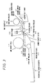
- Fig. 3 is a diagram showing in detail the thermal head 31 and its adjacent parts, providing a detailed illustration of how the ink sheet and the recording paper are transported within the facsimile apparatus.
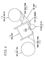
- Fig. 4 is an enlarged view of the head unit 16. The following description is given with reference to Fig. 3 in conjunction with Fig. 4.
- a plurality of recording paper sheets are loaded into the recording paper cassette 14 and are urged upward by means of a rotation plate 35. Both sides of the leading edge of the recording paper are held by pawls not shown.
- the pick-up roller 18 rotates, the top sheet of recording paper is pushed forward and fed with the leading edge riding over the pawls. This mechanism ensures that the recording paper is always fed one sheet at a time.
- the recording paper thus fed is passed through a pair of first paper-feed rollers 36 by being guided on a lower paper guide 34 and a first upper paper guide 33, and fed to the position between the platen roller 110 and the head 31.
- the head 31 and head frame 32, forming part of the head unit 16, also act to guide the transportation of the recording paper and the ink sheet.
- the recording paper printed at the position between the head 31 and the platen roller 110 is guided by the lower paper guide 34 and a second paper guide 37 and is transported by a pair of second paper-feed rollers 38 into the paper exit port 111 for discharge outside.
- the ink sheet 42 fed out of the ink sheet roll 17, is transported by being guided by a front head frame 32a, the head 31, and a rear head frame 32b, and is wound around the take-up roller 15.
- positional relationship at the portion of the head 31 is such that the head 31, the ink sheet 42, the recording paper, and platen roller 110 are stacked from top to bottom in this order.
- the head 31 has a heater with a heater dot density of eight dots per millimeter, extending along the full width of the recording paper in the depth direction in the plane of Fig. 3, and is pressed toward the platen roller 110 by a spring (not shown) exerting a constant pressure.
- a member 41 for frictionally tensioning the ink sheet 42 may be provided between the rear head frame 32b and the take-up roller 15.
- the simplest construction of the friction member is to use the rear head frame 32b itself, at least a portion thereof, as the friction member 41.
- the description hereinafter given assumes that the rear head frame 32b is constructed so that one end thereof located near the head 31 serves as the friction member 41.
- the head 31 in Fig. 4 is pressed by the spring against the platen roller 110, as earlier described.
- the ink sheet 42 is fed by relying solely on the rotating action of the platen roller 110.
- the ink sheet 42 is sandwiched between the head 31 and the platen roller 110. This is equivalent to holding the ink sheet 42 stationary under tension at the head 31.
- the take-up roller 15 takes up the printed portion of the ink sheet 42 with a strong rotational force. With this take-up tension, the friction member 41 can serve the function of frictionally tensioning the ink sheet when, as shown in Fig.
- the rear head frame 32b is constructed so that the friction member 41 protrudes beyond a reference line L1 toward the platen roller side, i.e., below the reference line L1 in the plane of Fig. 4, the reference line L1 being the line joining the head 31 to the take-up position of the take-up roller 15.
- the take-up tensional force applied to the ink sheet 42 at the print position of the head 31 is made greater at the widthwise edges of the ink sheet 42 than at the center thereof in order to prevent the ink sheet 42 from wrinkling with the center portion thereof shrinking due to the heating of the head 31 and thereby to prevent print failure. This also serves to prevent transport failure of the ink sheet 42.
- the friction member 41 which forcefully applies a frictional force to a portion of the ink sheet 42 lying in the section between the head 31 and the take-up roller 15, is disposed between the head 31 and the take-up roller 15 and along the full width of the ink sheet. Further, the frictional force of the friction member 41 is made greater at the center than at both end portions thereof. With this structure, the tensile force applied to both edges of the portion of the ink sheet 42 which faces the head 31 can be made greater than that applied to the center of that portion.
- frictional force of the friction member 41 can be made greater at the center than at both end portions thereof, for example, a first structure in which the length of contact between the ink sheet 42 and the friction member 41 is varied, a second structure in which the coefficient of friction of the friction member 41 is made lower at both end portions than at the center portion, and a third structure in which the coefficient of friction of the friction member 41 is made higher at the center portion than at both end portions.
- a first structure in which the length of contact between the ink sheet 42 and the friction member 41 is varied
- second structure in which the coefficient of friction of the friction member 41 is made lower at both end portions than at the center portion
- third structure in which the coefficient of friction of the friction member 41 is made higher at the center portion than at both end portions.
- Fig. 5 is a detailed perspective view showing the friction member 41 of the basic structure.
- the rear head frame 32b is used as the friction member 41.
- the friction member 41 is shown upside down from that shown in Fig. 4, and the ink sheet 42 is fed in the direction of ink sheet travel 56 shown by arrow 56.
- the rear head frame 32b is a member whose cross section cut along an imaginary plane perpendicular to the width direction of the ink sheet 42 is substantially formed in the shape of the letter L. Of all the surfaces of the rear head frame 32b, the surface most protruding beyond the reference line L1 toward the platen roller side is called a "friction portion".
- the friction portion is the surface that applies friction to the ink sheet 42.
- the first to third structures forming friction members 41B to 41D in the present invention are identical to the structure of a friction member 41A shown in Fig. 5, the only difference being in the structure of the respective friction portions.
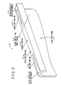
- Fig. 6 is a perspective view showing the friction member 41B of the first structure.
- both end portions 54B and 55B of a friction portion 52B are recessed to provide lower faces than a center portion 53B; that is, a first recess 71 is formed in one end portion 54B of the friction portion 52B, and a second recess 72 is formed in the other end portion 55B thereof.
- the length along which the center portion 53B of the friction portion 52B of Fig. 6 contacts the ink sheet 42 is made greater than the length along which each of the end portions 54B and 55B of the friction portion 52B of Fig. 6 contacts the ink sheet 42, so that the center portion 53B of the friction member 41B of Fig.
- the recesses 71 and 72 in the respective end portions are formed widest at the respective ends, the width gradually decreasing toward the center of the friction portion 52B.
- the friction member 41B of Fig. 6 can gradually reduce the tensile force with increasing distance from each widthwise end toward the center.
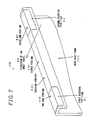
- Fig. 7 is a perspective view showing the friction member 41C of the second structure.
- a first fluorine-based film 61 is glued to one end portion 54C of the friction portion and a second fluorine-based film 62 to the other end portion 55C.
- a fluorine-based film has a lower coefficient of friction than members made of other materials.
- the friction portion 52C of the friction member 41C in Fig. 7 has a lower coefficient of friction at both end portions 54C and 55C than at a center portion 53C, relatively. Accordingly, in the structure of the friction member 41C in Fig. 7, the tensile force applied to both widthwise edges of the ink sheet 42 can be made greater than that applied to the widthwise center thereof.
- Fig. 8 is a perspective view showing a friction member 41D of the third structure.
- a center portion 53D of a friction portion 52D is covered with a substance having a high coefficient of friction.
- a substance 81 with a high coefficient of friction is applied only on the center portion 53D of the friction portion. This serves to reduce surface smoothness of the center portion of the friction portion 52D; as a result, the friction portion 52D of the friction member 41D in Fig. 8 has a lower coefficient of friction at both end portions 54D and 55D than at the center portion 53D, relatively. Accordingly, in the structure of the friction member 41D in Fig. 8, the tensile force applied to both widthwise edges of the ink sheet 42 can be made greater than that applied to the widthwise center thereof.
- a film with a high coefficient of friction may be glued to the center portion 53D of the friction portion, or the surface of the center portion 53D of the friction portion may be roughened using a sand blasting or like method.
- the tensile force applied to both widthwise edges of the ink sheet 42 can be made greater than that applied to the widthwise center thereof.
- the widthwise center portion of the ink sheet 42 is frequently used for printing, increasing the tendency of the center portion of the ink sheet to shrink due to subjection to the heat of the thermal head 31.
- Both edges of the ink sheet include portions not used for printing and, therefore, are less likely to be subjected to the heat of the head 31.
- the friction member for tensioning the ink sheet by forcefully applying friction to it is constructed so as to contact the full width of the ink sheet, and the frictional force of the friction member is made smaller at both end portions than at the center portion so that a greater tensile force is applied to both edge of the ink sheet.
- the width of the friction member for providing friction is varied in such a manner as to increase the length of contact along which the ink sheet contacts the center portion.
- the coefficient of friction of the friction member is varied between the center portion and the end portions to achieve the above purpose.
- Fig. 9 is a block diagram showing the electrical configuration of the above-described thermal transfer facsimile apparatus according to the present invention.
- the illustrated configuration concerns a conventional facsimile, and various other embodiments are also possible.
- the thermal transfer facsimile apparatus comprises a CPU 100, a document transport section 102, a document transmitting section 103, and a memory 104, in addition to the communications device 4 and a recording section 101 which includes the thermal transfer recording apparatus 3.
- the CPU 100 controls the functions of the devices 4 and 101 to 104 in the facsimile apparatus.
- the recording section 101 records images received by the communications device 4 onto the recording paper.
- the recording section 101 includes a thermal head driver.
- the document transport section 102 transports a document holding thereon an image to be transmitted.
- the document transmitting section 103 transmits the document via the communications device 4.
- the document transmitting section includes the document reading device.
- the memory 104 is used to store received images as well as abbreviated dialing and speed dialing numbers.
Landscapes
- Impression-Transfer Materials And Handling Thereof (AREA)
- Electronic Switches (AREA)
Applications Claiming Priority (2)
| Application Number | Priority Date | Filing Date | Title |
|---|---|---|---|
| JP23672498 | 1998-08-24 | ||
| JP10236724A JP2000062270A (ja) | 1998-08-24 | 1998-08-24 | 熱転写型記録装置 |
Publications (2)
| Publication Number | Publication Date |
|---|---|
| EP0982140A2 true EP0982140A2 (de) | 2000-03-01 |
| EP0982140A3 EP0982140A3 (de) | 2000-04-19 |
Family
ID=17004853
Family Applications (1)
| Application Number | Title | Priority Date | Filing Date |
|---|---|---|---|
| EP99306713A Withdrawn EP0982140A3 (de) | 1998-08-24 | 1999-08-24 | Thermotransferaufzeichnungsgerät |
Country Status (3)
| Country | Link |
|---|---|
| US (1) | US6380964B1 (de) |
| EP (1) | EP0982140A3 (de) |
| JP (1) | JP2000062270A (de) |
Cited By (3)
| Publication number | Priority date | Publication date | Assignee | Title |
|---|---|---|---|---|
| WO2002028657A1 (en) | 2000-10-05 | 2002-04-11 | Sagem Sa | Apparatus for making visible recordings on a record carrier with the aid of a thermal transfer foil |
| US7286150B2 (en) | 2002-03-21 | 2007-10-23 | Imperial Chemical Industries Inc. | Thermal transfer printing |
| CN109693455A (zh) * | 2017-10-20 | 2019-04-30 | 兄弟工业株式会社 | 热转印打印机 |
Families Citing this family (11)
| Publication number | Priority date | Publication date | Assignee | Title |
|---|---|---|---|---|
| US6727931B2 (en) * | 2002-09-12 | 2004-04-27 | Eastman Kodak Company | Preventing crease formation in donor web in dye transfer printer that can cause line artifact on print |
| US6859221B2 (en) * | 2003-03-18 | 2005-02-22 | Eastman Kodak Company | Preventing crease formation in donor web in dye transfer printer that can cause line artifact on print |
| US6757003B1 (en) * | 2003-03-18 | 2004-06-29 | Eastman Kodak Company | Preventing crease formation in donor web in dye transfer printer that can cause line artifact on print |
| US20050162504A1 (en) * | 2004-01-23 | 2005-07-28 | Alps Electric Co., Ltd. | Line thermal head and thermal-transfer line printer |
| US6977669B2 (en) * | 2004-02-26 | 2005-12-20 | Eastman Kodak Company | Preventing crease formation in donor web in dye transfer printer that can cause line artifact on print |
| KR20080007026A (ko) * | 2006-07-14 | 2008-01-17 | 삼성전자주식회사 | 화상형성장치 |
| US8081201B2 (en) | 2006-08-31 | 2011-12-20 | Dai Nippon Printing Co., Ltd. | Thermal transfer printer |
| JP5678551B2 (ja) * | 2010-09-29 | 2015-03-04 | シンフォニアテクノロジー株式会社 | プリンタ |
| KR101672031B1 (ko) * | 2014-06-02 | 2016-11-02 | 현대모비스 주식회사 | 차량용 램프 모듈 |
| JP7834685B2 (ja) * | 2023-04-24 | 2026-03-24 | 東芝テック株式会社 | プリンタ装置 |
| CN121608529B (zh) * | 2026-02-03 | 2026-04-21 | 湖南美松信息科技有限公司 | 一种高稳定抗褶皱热转印打印系统 |
Family Cites Families (9)
| Publication number | Priority date | Publication date | Assignee | Title |
|---|---|---|---|---|
| JPH0425486A (ja) | 1990-05-21 | 1992-01-29 | Seiko Epson Corp | 熱転写プリンタ |
| JP3094300B2 (ja) * | 1990-06-29 | 2000-10-03 | 株式会社日立製作所 | 熱転写記録装置 |
| JPH04148971A (ja) * | 1990-10-12 | 1992-05-21 | Seiko Epson Corp | 熱転写プリンタ |
| JPH0569624A (ja) * | 1990-11-29 | 1993-03-23 | Canon Inc | インクシートカートリツジ及び前記インクシートカートリツジを用いる記録装置 |
| JPH07266649A (ja) | 1994-03-31 | 1995-10-17 | New Oji Paper Co Ltd | 熱転写プリンタ |
| JPH08318656A (ja) * | 1995-05-25 | 1996-12-03 | Graphtec Corp | 熱転写記録装置 |
| JPH0939349A (ja) * | 1995-07-28 | 1997-02-10 | Graphtec Corp | インクリボン剥離機構 |
| JPH09272239A (ja) * | 1996-04-04 | 1997-10-21 | Nec Eng Ltd | ラインサーマルプリンタ |
| JP3770429B2 (ja) * | 1997-06-13 | 2006-04-26 | 富士写真フイルム株式会社 | インクリボン均一剥離手段付き熱転写装置 |
-
1998
- 1998-08-24 JP JP10236724A patent/JP2000062270A/ja active Pending
-
1999
- 1999-08-24 EP EP99306713A patent/EP0982140A3/de not_active Withdrawn
- 1999-08-24 US US09/379,638 patent/US6380964B1/en not_active Expired - Lifetime
Cited By (4)
| Publication number | Priority date | Publication date | Assignee | Title |
|---|---|---|---|---|
| WO2002028657A1 (en) | 2000-10-05 | 2002-04-11 | Sagem Sa | Apparatus for making visible recordings on a record carrier with the aid of a thermal transfer foil |
| US7286150B2 (en) | 2002-03-21 | 2007-10-23 | Imperial Chemical Industries Inc. | Thermal transfer printing |
| CN109693455A (zh) * | 2017-10-20 | 2019-04-30 | 兄弟工业株式会社 | 热转印打印机 |
| US11104153B2 (en) * | 2017-10-20 | 2021-08-31 | Brother Kogyo Kabushiki Kaisha | Thermal-transfer printer with a movable member movable to expose an ink ribbon supporting member |
Also Published As
| Publication number | Publication date |
|---|---|
| US6380964B1 (en) | 2002-04-30 |
| JP2000062270A (ja) | 2000-02-29 |
| EP0982140A3 (de) | 2000-04-19 |
Similar Documents
| Publication | Publication Date | Title |
|---|---|---|
| US6380964B1 (en) | Thermal transfer recording apparatus | |
| JP3318457B2 (ja) | カール矯正装置およびこれを備えたプリンタ | |
| EP0792752A2 (de) | Blatttransportgerät | |
| JP3879799B2 (ja) | 複合処理装置 | |
| JP3935310B2 (ja) | プリンタの媒体形状制御用内部紙案内 | |
| JP5140454B2 (ja) | シート材搬送機構およびプリンタ | |
| JP2009190799A (ja) | ロール紙給紙機構及び画像形成装置 | |
| JP2005047699A (ja) | 記録紙収納パック | |
| JP3629869B2 (ja) | インクジェットプリンタ | |
| JP3883754B2 (ja) | 両面印刷用プリンタ | |
| US5425588A (en) | Pivoting platen for use in printing device | |
| JP3977729B2 (ja) | プリンタ用ロール紙の芯材 | |
| JP3572002B2 (ja) | シート材搬送装置及び画像形成装置 | |
| JP3985563B2 (ja) | 画像形成方法 | |
| JP2951819B2 (ja) | ラインサーマルラベルプリンタ | |
| JP2912656B2 (ja) | シート供給装置 | |
| JP2900350B2 (ja) | ロール紙のカール矯正装置 | |
| JPH1148516A (ja) | 記録装置 | |
| JP2004196537A (ja) | 用紙搬送機構 | |
| JPH07251970A (ja) | シート材搬送装置及び画像形成装置 | |
| JP2001354338A (ja) | プリンタの用紙搬送機構 | |
| JPS59224378A (ja) | プリンタ用インクリボンの送り方法 | |
| JP2001253060A (ja) | インクジェットカートリッジを有するプリンター | |
| JP2975503B2 (ja) | ラインサーマルプリンタ | |
| JP2002128359A (ja) | 用紙のカール矯正方法 |
Legal Events
| Date | Code | Title | Description |
|---|---|---|---|
| PUAI | Public reference made under article 153(3) epc to a published international application that has entered the european phase |
Free format text: ORIGINAL CODE: 0009012 |
|
| AK | Designated contracting states |
Kind code of ref document: A2 Designated state(s): DE GB |
|
| AX | Request for extension of the european patent |
Free format text: AL;LT;LV;MK;RO;SI |
|
| PUAL | Search report despatched |
Free format text: ORIGINAL CODE: 0009013 |
|
| AK | Designated contracting states |
Kind code of ref document: A3 Designated state(s): AT BE CH CY DE DK ES FI FR GB GR IE IT LI LU MC NL PT SE |
|
| AX | Request for extension of the european patent |
Free format text: AL;LT;LV;MK;RO;SI |
|
| RIC1 | Information provided on ipc code assigned before grant |
Free format text: 7B 41J 2/325 A, 7B 41J 17/30 B, 7B 41J 35/08 B |
|
| 17P | Request for examination filed |
Effective date: 20000814 |
|
| AKX | Designation fees paid |
Free format text: AT BE |
|
| RBV | Designated contracting states (corrected) |
Designated state(s): DE GB |
|
| 17Q | First examination report despatched |
Effective date: 20031024 |
|
| STAA | Information on the status of an ep patent application or granted ep patent |
Free format text: STATUS: THE APPLICATION IS DEEMED TO BE WITHDRAWN |
|
| 18D | Application deemed to be withdrawn |
Effective date: 20040304 |