EP0982154A2 - Radzierblende - Google Patents
Radzierblende Download PDFInfo
- Publication number
- EP0982154A2 EP0982154A2 EP99305905A EP99305905A EP0982154A2 EP 0982154 A2 EP0982154 A2 EP 0982154A2 EP 99305905 A EP99305905 A EP 99305905A EP 99305905 A EP99305905 A EP 99305905A EP 0982154 A2 EP0982154 A2 EP 0982154A2
- Authority
- EP
- European Patent Office
- Prior art keywords
- wheel cover
- cover body
- wheel
- side fixture
- movable side
- Prior art date
- Legal status (The legal status is an assumption and is not a legal conclusion. Google has not performed a legal analysis and makes no representation as to the accuracy of the status listed.)
- Withdrawn
Links
- 230000005611 electricity Effects 0.000 claims abstract description 13
- 238000005286 illumination Methods 0.000 abstract description 2
- 239000003990 capacitor Substances 0.000 description 7
- 238000003780 insertion Methods 0.000 description 2
- 230000037431 insertion Effects 0.000 description 2
- 239000000463 material Substances 0.000 description 2
- 229920003002 synthetic resin Polymers 0.000 description 2
- 239000000057 synthetic resin Substances 0.000 description 2
- 208000031872 Body Remains Diseases 0.000 description 1
- 229920001875 Ebonite Polymers 0.000 description 1
- 239000000853 adhesive Substances 0.000 description 1
- 230000001070 adhesive effect Effects 0.000 description 1
- 235000012489 doughnuts Nutrition 0.000 description 1
- 239000002184 metal Substances 0.000 description 1
Images


Classifications
-
- B—PERFORMING OPERATIONS; TRANSPORTING
- B60—VEHICLES IN GENERAL
- B60B—VEHICLE WHEELS; CASTORS; AXLES FOR WHEELS OR CASTORS; INCREASING WHEEL ADHESION
- B60B7/00—Wheel cover discs, rings, or the like, for ornamenting, protecting, venting, or obscuring, wholly or in part, the wheel body, rim, hub, or tyre sidewall, e.g. wheel cover discs, wheel cover discs with cooling fins
- B60B7/20—Wheel cover discs, rings, or the like, for ornamenting, protecting, venting, or obscuring, wholly or in part, the wheel body, rim, hub, or tyre sidewall, e.g. wheel cover discs, wheel cover discs with cooling fins having an element mounted for rotation independently of wheel rotation
Definitions
- the present invention relates to a wheel cover for a motor vehicle; i.e. a passenger car, a truck or a bus.
- a conventional wheel cover comprises a wheel cover body covering the disc part of the wheel and a plurality of fitting pieces formed in the wheel cover body, for fixing to the disc part or the rim of the wheel. Because the above-mentioned wheel cover is fixed to the disc part or rim of the wheel with a plurality of fitments, people cannot see a design drawn on the wheel cover body because it rotates with the wheel, and therefore the design depicted thereon also rotates.
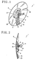
- Figs. 1 to 15 illustrate a first embodiment of the present invention wherein a wheel cover 1 is mounted on a wheel 3 of the vehicle: in this embodiment, it is mounted on a passenger car 2.
- the wheel cover 1 comprises a fixable side fixture 4, a movable side fixture 5, a wheel cover body 6 in the shape of a disc, rotating protection means of the wheel cover body 7, a dynamo 9 and an electric appliance 10.
- the fixable side fixture 4 is fixable mounted in a position so that the central part thereof can be positioned at the center of the wheel 3.
- the movable side fixture 5 is rotatably mounted to the central part of the fixable side fixture 4.
- the wheel cover body 6 is mounted to the movable side fixture 5 while the wheel cover body 6 has a space between itself and the wheel 3.
- Rotating protection means 7 prevents from the rotating as one with the wheel 3 and the wheel cover body 6.
- the dynamo 9 is mounted to The movable side fixture 5 such that the dynamo 9 is driven by drive means 8 due to rotation of the wheel 3, that is, of the fixable side fixture 4.
- the electric appliance 10 is used in electricity generated by the dynamo 9 and is mounted to the movable side fixture 5 or the wheel cover body 6.
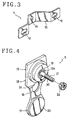
- the fixable side fixture 4 comprises a fixable side fixture body 13 having an axle insertion hole 14 in the central part of the fixture body. Wheel bolt holes 12,12 located at both sides thereof are provided to receive wheel bolts 11,11 for fixing.
- the fixable side fixture body 13 is formed in the shape of a roof.
- the axle insertion hole 14 is located in the central portion of the fixable side fixture body 13.
- the movable side fixture 5 comprises a movable side fixture body 18, a bearing 19, an axle 21, a nut 22, a weight 23 and a dynamo mounting portion 24.
- the movable side fixture body 18 is made of hard rubber or synthetic resin materials; the upper part thereof consists of a fitting piece 15 in the shape of a square; a weight supporting part 17 through a connection 16 is located in the lower part thereof.
- the bearing 19 is fixed to the nearly central part of the fitting piece 15 of the movable side fixture body 18.
- the axle 21 is fitably fixed to a rotating ring 19 a located at center portion of the bearing 19, inserted through an axle insertable hole 14 of the fixable side fixture 4. Thread areas 20 are present at the outside section of the movable side fixture.
- the nut 22 fixes the axle 21 to the fixable side fixture 4 by securing to the thread 20 of the axle 21.
- the weight 23 as the rotating protection means 7 is fixed with adhesive to the weight supporting part 17.
- the dynamo mounting portion 24 is formed in the connection
- the wheel cover body 6 On the wheel cover body 6 is drawn a design 25; the design may be, for example, an advertisement.
- the wheel cover body 6 is made of metal or synthetic resin material and comprises a wheel cover housing 26, a fitting part 27 and an air current guide part 28.
- the wheel cover housing 26 is in the shape of a disc.
- the fitting part 27 is located in the central part of the inner wall of the wheel cover housing 26; as it is formed in the shape of a channel and widens out to an angle, it can be removably inserted.
- the air current guide part 28 takes the shape of a nose and is formed in the shape of the portion which is positioned to the rear on the wheel cover housing 26 when the vehicle is in motion.
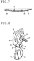
- the dynamo 9 is installed to the dynamo mounting portion 24 of the movable side fixture 5; as it is formed in the shape of a thin type.
- Drive means 8 of the dynamo 9, as illustrated in Fig.9. comprises a driving pulley 31, a drive pulley 32 and a belt 33.
- the driving pulley 31 is mounted to a shaft 30 of a rotor 29 in the dynamo 9.
- the drive pulley 32 is inserted on the axle 21 of the movable side fixture 5 and interposed fixedly between the rotating ring 19a of the bearing 19 and the fixable side fixture 4.
- the electric appliance 10 comprises a capacitor 35 mounted to the movable side fixture 5 and an indicator 36 mounted to the wheel cover body 6 which is connected to the capacitor 35, the indicator 36 used for illuminations.
- a driving pulley 31, a drive pulley 32 and a belt 33 as drive means 8 which are installed to the side of a wheel 3
- the present invention may use the driving pulley 31, drive pulley 32 and a belt as drive means 8 which are installed as to situate between the wheel cover body 6 and the movable side fixture body 18.
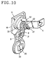
- the dynamo 9 and the capacitor 35 are mounted to the movable side fixture 5.
- the axle 21 of the movable side fixture 5 is inserted into the drive pulley 32, and the belt 33 is attached to the drive pulley 32.
- the nut 22 is screwed into the thread 20 of the axle 21 and the movable side fixture 5 is mounted to the fixable side fixable side fixture 4 such that the drive pulley 32 is integrally provided.
- the fitting piece 15 of the movable side fixture 5 is set in the fitting part 29 of the wheel cover 6. Then, the movable side fixture body 18 improves the flexibility of the arrangement, and the weight supporting part 17 attaches closely with the inner wall of the wheel cover body 6 by pushing pressure.
- the air current guide part 28 of the wheel cover housing 26 as illustrated in Fig.12 is directed to the backward of the passenger car 2 due to the weight 23 of the movable side fixture 5 as rotating protection means 7.
- the fixable side fixture 4 fixed to the wheel 3 will rotate with the wheel 3 when the car 2 moves, but rotation of the wheel cover body 6 is prevented because the wheel cover body 6 is mounted to the movable side fixture 5 which is mounted rotatably to the fixable side fixure 4, it becomes non-rotating state.
- the drive pulley 32 is fixed to the fixable side fixture 4 rotates due to the rotating of the wheel 3. Then, the driving pulley 31 rotates through the belt 33, and the rotor 29 in the dynamo 9 allows to ratate and electricity is generated. Electricity generated by the dynamo 9 is stored by the capacitor 35, and electricity is supplied to the indicator 36.
- Figs.16 to 18 illustrate a second embodiment of the present invention. It is distinguished from the first embodiment in that the movable side fixture 5A includes a fitting piece 40 for the outer part of the connection 13, the fitting piece 40 having terminals 39,39 connected to the capacitor 35, the terminals 39,39 respectively having screw holes 38,38, in that the wheel cover body 7A includes a fitable hole 41 through which a fitting piece 40 of the movable side fixture 5A is inserted, and in that an indicator 36A is mounted to the wheel cover body 6A and formed terminals 43,43, to which the screw holes 38, 38 of the terminals 39,39 on the fitting piece 40 are connected by screws 42,42.
- a wheel cover 1A with the movable side fixture 5A wheel cover body 6A and indicator 36A according to the second embodiment will have similar advantages to that according to the first embodiment; in addition, connecting operations with the indicator 36 and capacitor 35 can be done easily.
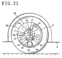
- Figs.19 to 21 illustrate a third embodiment of the present invention. It is distinguished from the second embodiment in that the fixable side fixture 4A has three legs 44,44,44; these legs are capable of fixing to the vehicle 2 and is able to fix to the wheel 3 with the uneven number of wheel bolts 11.
- a wheel cover 1B with the fixable side fixture 4B according to the third embodiment will have similar advantages to that according to the second embodiment.
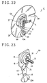
- Figs.22 to 24 illustrate a fourth embodiment of the present invention. It is distinguished from the second embodiment in that a fan-shaped weight 23A is pivotably mounted to a free end of the connection 16 at the movable side fixture 5 by a pivot pin 45, capable of using both as a fitting piece.
- a wheel cover 1C with the movable side fixture 5B having the rotatable weight 23A according to the fourth embodiment will have similar advantages to that according to the second embodiment.
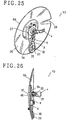
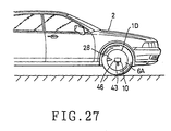
- Figs.25 to 27 illustrate a fifth embodiment of the present invention. It is distinguished from the second embodiment in that a transmitter of electromagnetic wave 46 can transmit electromagnetic wave as the electric appliance 10 and allows to inform a place in which electromagnetic wave is transmitted.
- a wheel cover 1D according to the fourth embodiment will have similar advantages to that according to the second embodiment; in addition, when the vehicle is in motion, the transmitter transmits electromagnetic wave automatically, and its wave is received in receiving bases, so that the vehicle is confirmed where it is.
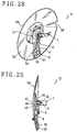
- Figs.28 to 30 illustrate a sixth embodiment of the present invention. It is distinguished from the second embodiment in that a sound device 49 as the electric appliance 10 is mounted to the wheel cover body 6A, having a receiver 48 sounds warning melodies due to switch on and off a remote control 47 from the cabin, i.e. a driver's seat, of the vehicle.
- a sound device 49 as the electric appliance 10 is mounted to the wheel cover body 6A, having a receiver 48 sounds warning melodies due to switch on and off a remote control 47 from the cabin, i.e. a driver's seat, of the vehicle.
- a wheel cover 1E is mounted to the vehicle with lower noise such as an electric car and is used in it, the driver may inform people or other vehicles of his or her presence easily without surprising.
- Figs.31 to 35 illustrate a seventh embodiment of the present invention. It is distinguished from the second embodiment in that an axle 30A of the rotor 29 is inserted into the fitable hole 14 of the fixable side fixture 4 and fixed by a nut 50, and in that a dynamo 9A includes a stator 51 which covers rotatably an outer circumferential portion of the rotor 29, the stator 51 fixed to a substantially central portion of the fitting piece 15 of the movable side fixture 5A.
- a wheel cover 1F with the dynamo 9A according to the seventh embodiment will have similar advantages to that according to the second embodiment.
- the dynamo 9A as shown in Fig.35 comprises the rotor 29 and the stator 51 fixed to the movable side fixture 5A.
- the stator 29 further comprises a magnet 56 in the shape of a doughnut fixed to The axle 30A through a holder 55, in which N poles and S poles are alternately arranged.
- the stator 51 further comprises a coil 58, a holder 59, and a cover 60 which are mounted to the axle 30A through a bobbin 57 such that the stator 51 is located at a side surface portion of the magnet 56 of the rotor 29.
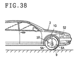
- Figs.36 to 38 illustrate an eighth embodiment of the present invention. It is distinguished from The second embodiment in that the dynamo 9 is connected to a battery 52 through wires 54,54 attached to a body 53 such that electricity generated by the dynamo 9 is charged by the battery 52 of the passenger car 2.
- a wheel cover 1G with the according to the eighth embodiment will have similar advantages to that according to the second embodiment; in addtion, the wires 54,54 can be used as a rotating protection means for the wheel cover body 6A.
- the wheel cover body can be replaced simply with other wheel cover body.
Landscapes
- Engineering & Computer Science (AREA)
- Mechanical Engineering (AREA)
- Connection Of Motors, Electrical Generators, Mechanical Devices, And The Like (AREA)
Applications Claiming Priority (3)
| Application Number | Priority Date | Filing Date | Title |
|---|---|---|---|
| JP25459298 | 1998-08-24 | ||
| JP25459298A JP3162673B2 (ja) | 1998-08-24 | 1998-08-24 | ホイールカバー |
| US09/144,192 US6045195A (en) | 1998-08-24 | 1998-08-31 | Wheel cover |
Publications (2)
| Publication Number | Publication Date |
|---|---|
| EP0982154A2 true EP0982154A2 (de) | 2000-03-01 |
| EP0982154A3 EP0982154A3 (de) | 2003-01-02 |
Family
ID=26541755
Family Applications (1)
| Application Number | Title | Priority Date | Filing Date |
|---|---|---|---|
| EP99305905A Withdrawn EP0982154A3 (de) | 1998-08-24 | 1999-07-26 | Radzierblende |
Country Status (3)
| Country | Link |
|---|---|
| US (1) | US6045195A (de) |
| EP (1) | EP0982154A3 (de) |
| JP (1) | JP3162673B2 (de) |
Cited By (2)
| Publication number | Priority date | Publication date | Assignee | Title |
|---|---|---|---|---|
| WO2002032694A1 (de) | 2000-10-17 | 2002-04-25 | Bernd Litzka | Radverkleidung zur abdeckung der felge eines fahrzeugrades |
| DE102022131509A1 (de) * | 2022-11-29 | 2024-05-29 | Demmel Aktiengesellschaft | Abdeck- oder Nabenkappe mit beleuchtetem Radnabenemblem und feststehendem Logo |
Families Citing this family (50)
| Publication number | Priority date | Publication date | Assignee | Title |
|---|---|---|---|---|
| US6471302B1 (en) * | 1998-08-17 | 2002-10-29 | Logo-Motive Systems B.V. | Hub cap with picture |
| US6494473B1 (en) * | 2000-04-04 | 2002-12-17 | Sossy Baghboian | Tire protector |
| US6554370B2 (en) * | 2000-08-11 | 2003-04-29 | David Fowlkes | Wheel spinner assembly independently rotatable relative to a corresponding wheel |
| US6443529B1 (en) * | 2000-08-17 | 2002-09-03 | Curtis A. Williams | Assembly with a non-rotatable wheel cover disc |
| US6443531B1 (en) * | 2000-09-21 | 2002-09-03 | Mckechnie Vehicle Components (Usa), Inc. | Method for manufacturing a wheel cover |
| US6517167B2 (en) * | 2000-11-20 | 2003-02-11 | Scott Baker | Wheel mounted decorative member |
| NL1018623C1 (nl) * | 2001-07-24 | 2002-08-27 | Paul Johan Willem Mari Nooijen | Verstelbaar contragewicht voor stationaire wieldop. |
| US6595596B1 (en) * | 2002-04-23 | 2003-07-22 | John G. Polka | Method and apparatus for attaching a cover to a wheel of a truck |
| US6637830B1 (en) | 2002-06-17 | 2003-10-28 | Walter Burgess | Spinable wheel cover |
| US6637831B1 (en) * | 2002-07-02 | 2003-10-28 | Kwang-Tai Kim | Wheel cover for automobiles |
| US20040183359A1 (en) * | 2003-03-18 | 2004-09-23 | David Fowlkes | Wheel spinner assembly independently rotatable relative to a corresponding wheel |
| US20050093362A1 (en) * | 2003-10-31 | 2005-05-05 | Jorge Alicea | Oscillating wheel accessory |
| KR100546249B1 (ko) * | 2003-12-15 | 2006-01-26 | 김헌규 | 차량의 휠커버 |
| US6857709B1 (en) | 2003-12-16 | 2005-02-22 | Aai Technology Inc. | Non-rotating wheel cover |
| US20050140201A1 (en) * | 2003-12-29 | 2005-06-30 | Wen-Chang Wang | Wheel cover for automobile |
| US6945609B2 (en) * | 2004-02-13 | 2005-09-20 | Advance Engineering Technology | Wheel cover apparatus and associated methods |
| US7014273B1 (en) * | 2004-03-22 | 2006-03-21 | Billy Yang | Spoked wheel spinner with non-rotating cap |
| US7175240B2 (en) * | 2004-09-09 | 2007-02-13 | Karl Anthony Fultz | Revolving ornamentation for wheel |
| US7389600B2 (en) * | 2004-10-29 | 2008-06-24 | Baker Scott B | Motor-driven decorative spinner for vehicles |
| US7472966B2 (en) * | 2005-02-25 | 2009-01-06 | Static Media Group, Llc | Wheel cover assembly having stationary display and base member for mounting to a wheel |
| US7472967B2 (en) * | 2005-09-21 | 2009-01-06 | Static Media Group, Llc | Vehicle wheel display assembly |
| US20060255652A1 (en) * | 2005-02-25 | 2006-11-16 | Robert Kaufman | Vehicle wheel display assembly |
| US20060277806A1 (en) * | 2005-02-25 | 2006-12-14 | Dovale Anthony J Jr | Vehicle Wheel Display Assembly |
| US20070200421A1 (en) * | 2006-02-24 | 2007-08-30 | Dovale Anthony J Jr | Wheel cover |
| WO2006137618A1 (en) * | 2005-06-24 | 2006-12-28 | Mehae Sun | Non-rotation advertising apparatus attached to car wheel |
| JP4105737B2 (ja) * | 2005-11-25 | 2008-06-25 | 和直 亀山 | ホイールカバー |
| US20070167273A1 (en) * | 2006-01-13 | 2007-07-19 | Nissan Technical Center North America, Inc. | Reverse spinning wheel cover |
| US20080023507A1 (en) * | 2006-07-26 | 2008-01-31 | Uebler E Alan | Spare tire cover having interchangeable graphic displays |
| US7547076B2 (en) * | 2007-01-24 | 2009-06-16 | Prestige Autotech Corporation | Wheel covering system |
| US20080252137A1 (en) * | 2007-01-24 | 2008-10-16 | Prestige Autotech Corporation | Wheel covering system |
| JP5325728B2 (ja) * | 2009-06-19 | 2013-10-23 | 好晃 岡本 | 低騒音自動車の警報装置 |
| US8814253B1 (en) | 2011-04-21 | 2014-08-26 | Flowbelow, LLC | Aerodynamic quarter fender assembly and construction method |
| EP2731805B1 (de) | 2011-07-12 | 2021-05-05 | FlowBelow Aero, Inc. | Radkappensystem |
| US9801325B2 (en) * | 2012-06-28 | 2017-10-31 | Joel Wills | Hub cover for agriculture purposes |
| HK1215229A1 (zh) | 2012-11-01 | 2016-08-19 | FlowBelow Aero, Inc. | 氣動系統和可調整流罩 |
| US9120446B2 (en) * | 2012-12-12 | 2015-09-01 | Combination Wheels, Llc | Wheel locking system |
| US9365074B2 (en) * | 2013-03-15 | 2016-06-14 | RealWheels Corporation | Wheel cover assembly and method of mounting |
| US10688554B2 (en) | 2013-09-16 | 2020-06-23 | Harry Bazerkanian | Non-rotating wheel cap |
| US9327340B1 (en) | 2013-09-16 | 2016-05-03 | Harry Bazerkanian | Method and apparatus for constructing a floating wheel cap |
| EP3142866A4 (de) * | 2014-05-13 | 2018-01-10 | Hutchinson S.A. | Reifenabschirmungsbefestigungssystem |
| CA2925195C (en) * | 2016-03-29 | 2016-12-13 | Juan Carlos Castro-Villanueva | The non-rotating center cap |
| US10046597B2 (en) * | 2016-09-04 | 2018-08-14 | Yen-Ching Wang | Automobile wheel cover |
| WO2018085791A1 (en) | 2016-11-04 | 2018-05-11 | FlowBelow Aero, Inc. | Chassis mounted energy extraction and delivery system |
| US10654529B2 (en) | 2017-06-24 | 2020-05-19 | FlowBelow Aero, Inc. | Aerodynamic systems and fairings with fairing caps |
| WO2019014503A1 (en) | 2017-07-12 | 2019-01-17 | FlowBelow Aero, Inc. | AERODYNAMIC TOOLBOX SET |
| US10882571B2 (en) | 2017-07-30 | 2021-01-05 | FlowBelow Aero, Inc. | Rotatable aerodynamic fairing system |
| US10703132B2 (en) | 2017-09-22 | 2020-07-07 | Consolidated Metco, Inc. | Wheel cover |
| US11072377B2 (en) | 2018-09-04 | 2021-07-27 | Lund, Inc. | Removable fairing |
| US11667151B2 (en) | 2019-03-01 | 2023-06-06 | Consolidated Metco, Inc. | Wheel cover |
| US11767064B2 (en) | 2021-01-12 | 2023-09-26 | FlowBelow Aero, Inc. | Spring-biased mud flap hanger with improved pivoting motion guidance |
Family Cites Families (32)
| Publication number | Priority date | Publication date | Assignee | Title |
|---|---|---|---|---|
| CA541032A (en) * | 1957-05-21 | A. Lyon George | Wheel structure | |
| US1432274A (en) * | 1922-05-18 | 1922-10-17 | Braucher Edward Franklin | Advertising disk for automobile wheels |
| US1478475A (en) * | 1923-04-18 | 1923-12-25 | Jago Alfred Charles | Advertising device for road and other vehicles |
| US1665437A (en) * | 1925-03-16 | 1928-04-10 | William N Booth | Vehicle wheel |
| US2130220A (en) * | 1937-10-08 | 1938-09-13 | George D Ball | Nonrotatable hub cap |
| US2169237A (en) * | 1938-01-04 | 1939-08-15 | Gasco Pete | Stationary ornament for wheel hub caps |
| US2548070A (en) * | 1948-11-22 | 1951-04-10 | Arthur M Ryan | Advertising display device |
| US2631204A (en) * | 1949-04-01 | 1953-03-10 | Willys Overland Motors Inc | Switch actuating means |
| US2707131A (en) * | 1953-01-07 | 1955-04-26 | Sundberg & Ferar | Wheel ornament holding structure |
| US2759282A (en) * | 1953-01-29 | 1956-08-21 | Lecourt Valere | Display disc attachment device |
| US2762469A (en) * | 1953-09-25 | 1956-09-11 | Lyon George Albert | Wheel cover |
| US2754154A (en) * | 1954-11-01 | 1956-07-10 | Solow Benjamin | Stationary hub cap cover |
| US2869262A (en) * | 1957-06-03 | 1959-01-20 | Charles D Lucas | Wheel-supported advertizing signs |
| US2997344A (en) * | 1959-12-28 | 1961-08-22 | Levi B Whiteman | Wheel cover |
| US3219391A (en) * | 1964-03-27 | 1965-11-23 | Gustave Miller | Revolving wheel disc cover |
| US3722958A (en) * | 1970-12-23 | 1973-03-27 | W Marshall | Rotative wheel covers, and the like |
| CA925539A (en) * | 1971-02-18 | 1973-05-01 | Titze Ronald | Wheel and tire cover |
| US4040582A (en) * | 1975-09-09 | 1977-08-09 | Krauss Ronald C | Wind power accessory for a vehicle wheel |
| US4214683A (en) * | 1978-11-14 | 1980-07-29 | Tale-Lite Systems, Inc. | Illuminated wheel cover |
| JPS60166602U (ja) * | 1984-04-14 | 1985-11-05 | マルイ工業株式会社 | 合成樹脂製ホイ−ルカバ− |
| JPS6181201A (ja) * | 1984-09-27 | 1986-04-24 | Yutaka Matsushita | フリ−ホイ−ルキヤツプ |
| KR900005370Y1 (ko) * | 1988-02-02 | 1990-06-18 | 박승문 | 정지광고판을 갖는 자동차 휠캡 |
| JPH01178101U (de) * | 1988-06-07 | 1989-12-20 | ||
| US4981329A (en) * | 1989-11-02 | 1991-01-01 | Koch Paul E | Non moving wheel cover |
| US5190354A (en) * | 1991-05-13 | 1993-03-02 | Serge Levy | Vehicle wheel cover |
| US5263770A (en) * | 1991-11-07 | 1993-11-23 | Goudey Robert B | Vehicle wheel cover |
| US5588715A (en) * | 1994-06-20 | 1996-12-31 | Harlen; Charles D. | Non-rotating wheel cover assembly |
| US5490342A (en) * | 1994-07-13 | 1996-02-13 | Rutterman; Michael J. | Non-rotating wheel cover |
| US5659989A (en) * | 1994-07-13 | 1997-08-26 | Hsiao; Leslie | Wheel cover |
| US5876108A (en) * | 1995-08-03 | 1999-03-02 | Chien; Tseng Lu | Illuminated rotating object |
| US5957542A (en) * | 1997-05-30 | 1999-09-28 | Boothe; Ralph T. | Theft-proof non-rotating wheel cover with replaceable ornament |
| AU5832498A (en) * | 1998-03-11 | 1999-09-23 | Miki Fujiwara | Wheel cover |
-
1998
- 1998-08-24 JP JP25459298A patent/JP3162673B2/ja not_active Expired - Fee Related
- 1998-08-31 US US09/144,192 patent/US6045195A/en not_active Expired - Fee Related
-
1999
- 1999-07-26 EP EP99305905A patent/EP0982154A3/de not_active Withdrawn
Non-Patent Citations (1)
| Title |
|---|
| None |
Cited By (3)
| Publication number | Priority date | Publication date | Assignee | Title |
|---|---|---|---|---|
| WO2002032694A1 (de) | 2000-10-17 | 2002-04-25 | Bernd Litzka | Radverkleidung zur abdeckung der felge eines fahrzeugrades |
| DE102022131509A1 (de) * | 2022-11-29 | 2024-05-29 | Demmel Aktiengesellschaft | Abdeck- oder Nabenkappe mit beleuchtetem Radnabenemblem und feststehendem Logo |
| DE102022131509B4 (de) * | 2022-11-29 | 2025-05-15 | Demmel Aktiengesellschaft | Abdeck- oder Nabenkappe mit beleuchtetem feststehendem Logo |
Also Published As
| Publication number | Publication date |
|---|---|
| JP3162673B2 (ja) | 2001-05-08 |
| US6045195A (en) | 2000-04-04 |
| JP2000062401A (ja) | 2000-02-29 |
| EP0982154A3 (de) | 2003-01-02 |
Similar Documents
| Publication | Publication Date | Title |
|---|---|---|
| US6045195A (en) | Wheel cover | |
| US20080001467A1 (en) | Wheel spinner assembly | |
| US4893877A (en) | Self-generated lighted hubcab | |
| EP0210219B1 (de) | Beleuchtungsanordnung für fahrzeugräder | |
| US6239701B1 (en) | Vehicle locator light | |
| US20050099820A1 (en) | Wheel illumination device | |
| EP1047576A1 (de) | Spiegelanordnung mit einzigem drehgelenk und sicherheitsbeleuchtung | |
| US20040042206A1 (en) | Automatic power-generating device for decorative lamps | |
| EP0791496A3 (de) | Antriebsradanordnung und Spielzeugauto mit derartiger Radanordnung | |
| US6382820B1 (en) | Illuminating novelty device for a hubcap | |
| CN212360558U (zh) | 一种混合动力摩托车离合器 | |
| US20030132723A1 (en) | Light generator for a rotatable object | |
| HK1026178A (en) | Wheel cover | |
| US20020172036A1 (en) | Automatic power generating device in combination with illumination lamps mounted to wheels | |
| US7413260B2 (en) | Motorized spinner for automotive wheels | |
| US6266844B1 (en) | Vehicle windshield wiper assembly incorporating cable and pulley drive system and remote positioned electric motor | |
| US20050093362A1 (en) | Oscillating wheel accessory | |
| US11623561B2 (en) | Wheel illumination apparatus | |
| CN110561968A (zh) | 汽车发光定标轮毂盖 | |
| JP2001115945A (ja) | 乗物搭載型風力発電装置 | |
| KR20100006246U (ko) | 자동차 발광휠 | |
| US7389600B2 (en) | Motor-driven decorative spinner for vehicles | |
| JP3124070U (ja) | 車両用発光装置 | |
| KR910006733Y1 (ko) | 조명기능을 갖는 차량용 보조 휘일캡 | |
| JPH0463737A (ja) | 警告灯内蔵型ホイールカバー |
Legal Events
| Date | Code | Title | Description |
|---|---|---|---|
| PUAI | Public reference made under article 153(3) epc to a published international application that has entered the european phase |
Free format text: ORIGINAL CODE: 0009012 |
|
| AK | Designated contracting states |
Kind code of ref document: A2 Designated state(s): AT BE CH CY DE DK ES FI FR GB GR IE IT LI LU MC NL PT SE |
|
| AX | Request for extension of the european patent |
Free format text: AL;LT;LV;MK;RO;SI |
|
| PUAL | Search report despatched |
Free format text: ORIGINAL CODE: 0009013 |
|
| AK | Designated contracting states |
Kind code of ref document: A3 Designated state(s): AT BE CH CY DE DK ES FI FR GB GR IE IT LI LU MC NL PT SE |
|
| AX | Request for extension of the european patent |
Free format text: AL;LT;LV;MK;RO;SI |
|
| 17P | Request for examination filed |
Effective date: 20030702 |
|
| AKX | Designation fees paid |
Designated state(s): AT BE CH CY DE DK ES FI FR GB GR IE IT LI LU MC NL PT SE |
|
| 17Q | First examination report despatched |
Effective date: 20040423 |
|
| GRAP | Despatch of communication of intention to grant a patent |
Free format text: ORIGINAL CODE: EPIDOSNIGR1 |
|
| GRAS | Grant fee paid |
Free format text: ORIGINAL CODE: EPIDOSNIGR3 |
|
| STAA | Information on the status of an ep patent application or granted ep patent |
Free format text: STATUS: THE APPLICATION IS DEEMED TO BE WITHDRAWN |
|
| 18D | Application deemed to be withdrawn |
Effective date: 20060201 |
|
| REG | Reference to a national code |
Ref country code: HK Ref legal event code: WD Ref document number: 1026178 Country of ref document: HK |