EP0982189A2 - Procédé de commande du dispositif de commutation d'une lampe - Google Patents
Procédé de commande du dispositif de commutation d'une lampe Download PDFInfo
- Publication number
- EP0982189A2 EP0982189A2 EP99117064A EP99117064A EP0982189A2 EP 0982189 A2 EP0982189 A2 EP 0982189A2 EP 99117064 A EP99117064 A EP 99117064A EP 99117064 A EP99117064 A EP 99117064A EP 0982189 A2 EP0982189 A2 EP 0982189A2
- Authority
- EP
- European Patent Office
- Prior art keywords
- electrical power
- switching device
- operational
- power
- coil
- Prior art date
- Legal status (The legal status is an assumption and is not a legal conclusion. Google has not performed a legal analysis and makes no representation as to the accuracy of the status listed.)
- Granted
Links
Images


Classifications
-
- B—PERFORMING OPERATIONS; TRANSPORTING
- B60—VEHICLES IN GENERAL
- B60Q—ARRANGEMENT OF SIGNALLING OR LIGHTING DEVICES, THE MOUNTING OR SUPPORTING THEREOF OR CIRCUITS THEREFOR, FOR VEHICLES IN GENERAL
- B60Q1/00—Arrangement of optical signalling or lighting devices, the mounting or supporting thereof or circuits therefor
- B60Q1/02—Arrangement of optical signalling or lighting devices, the mounting or supporting thereof or circuits therefor the devices being primarily intended to illuminate the way ahead or to illuminate other areas of way or environments
- B60Q1/04—Arrangement of optical signalling or lighting devices, the mounting or supporting thereof or circuits therefor the devices being primarily intended to illuminate the way ahead or to illuminate other areas of way or environments the devices being headlights
- B60Q1/14—Arrangement of optical signalling or lighting devices, the mounting or supporting thereof or circuits therefor the devices being primarily intended to illuminate the way ahead or to illuminate other areas of way or environments the devices being headlights having dimming means
- B60Q1/1415—Dimming circuits
-
- B—PERFORMING OPERATIONS; TRANSPORTING
- B60—VEHICLES IN GENERAL
- B60Q—ARRANGEMENT OF SIGNALLING OR LIGHTING DEVICES, THE MOUNTING OR SUPPORTING THEREOF OR CIRCUITS THEREFOR, FOR VEHICLES IN GENERAL
- B60Q1/00—Arrangement of optical signalling or lighting devices, the mounting or supporting thereof or circuits therefor
- B60Q1/02—Arrangement of optical signalling or lighting devices, the mounting or supporting thereof or circuits therefor the devices being primarily intended to illuminate the way ahead or to illuminate other areas of way or environments
- B60Q1/04—Arrangement of optical signalling or lighting devices, the mounting or supporting thereof or circuits therefor the devices being primarily intended to illuminate the way ahead or to illuminate other areas of way or environments the devices being headlights
- B60Q1/06—Arrangement of optical signalling or lighting devices, the mounting or supporting thereof or circuits therefor the devices being primarily intended to illuminate the way ahead or to illuminate other areas of way or environments the devices being headlights adjustable, e.g. remotely-controlled from inside vehicle
- B60Q1/076—Arrangement of optical signalling or lighting devices, the mounting or supporting thereof or circuits therefor the devices being primarily intended to illuminate the way ahead or to illuminate other areas of way or environments the devices being headlights adjustable, e.g. remotely-controlled from inside vehicle by electrical means including means to transmit the movements, e.g. shafts or joints
-
- F—MECHANICAL ENGINEERING; LIGHTING; HEATING; WEAPONS; BLASTING
- F21—LIGHTING
- F21S—NON-PORTABLE LIGHTING DEVICES; SYSTEMS THEREOF; VEHICLE LIGHTING DEVICES SPECIALLY ADAPTED FOR VEHICLE EXTERIORS
- F21S41/00—Illuminating devices specially adapted for vehicle exteriors, e.g. headlamps
- F21S41/60—Illuminating devices specially adapted for vehicle exteriors, e.g. headlamps characterised by a variable light distribution
- F21S41/65—Illuminating devices specially adapted for vehicle exteriors, e.g. headlamps characterised by a variable light distribution by acting on light sources
- F21S41/657—Illuminating devices specially adapted for vehicle exteriors, e.g. headlamps characterised by a variable light distribution by acting on light sources by moving light sources
Definitions
- the invention relates to a method and apparatus for control of a lamp. Specifically, the invention is directed to a method and apparatus for controlling a vehicle headlight that uses a single light source (such as a metal halide discharge lamp, etc.) and that is equipped with a beam-type switching device for switching between high beam and low beam.
- a single light source such as a metal halide discharge lamp, etc.
- Fig. 7 shows an example of the construction of a related art type headlamp 90.
- This headlamp 90 is equipped with a light source base 91, which has a fulcrum 91a.
- a single light source 92 attached to light source base 91 has a lumination source 92a.
- a solenoid 93 is provided at the tip of the opposite side of fulcrum 91a of light source base 91. Beam-type switching is carried out by activating solenoid 93 and shifting the lumination source 92a relative to reflector 94 from a low beam position to a high beam position.
- the solenoid 93 must maintain lumination source 92a in the high beam position during the time period in which the vehicle is driven in the high beam position. It is anticipated that the application of operational electrical power to the solenoid 93 will occur continuously for a rather long time period, for example, during lengthy travel on a high-speed highway. Lumination source 92a returns from the high beam position to the low beam position upon deactivation of the solenoid 93.
- the solenoid 93 utilized by the related art headlight 90 requires comparatively high electrical power at the start of movement from the low beam position to the high beam position since plunger 93b is distant from solenoid body 93a at the start of movement.
- solenoid 93 Although sufficient electrical power is supplied to begin movement of solenoid 93, as explained previously, this same electrical power is then continuously applied during the time that the vehicle is driven while using the high beam. Therefore excessive heating due to the continuous application of a great deal of electrical power to solenoid 93 occurs and a large-scale size solenoid 93 is necessary to avoid overheating.
- the related art headlight results in problems to be solved such as higher cost, increased weight, overheating, malfunctioning, etc.
- the invention relates to a method for controlling a switching device for switching between high beam and low beam in a vehicle lamp which includes providing an initial application of operational electrical power to the switching device, and lowering said operational electrical power after a specific time period has passed after initial application of operational electrical power.
- the invention also relates to an apparatus such as a headlight capable of switching between a high beam mode and a low beam mode including a switching device activatable by an initial application of operational electrical power, and electrical power reducing means for lowering said operational electrical power after a specific time period has passed after initial application of operational electrical power.
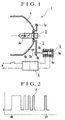
- Fig. 1 shows an embodiment of the invention in which a headlamp 1 includes a beam-type switching device.
- Headlamp 1 can include a light source base 2 which is constructed from appropriate components such as fulcrum 2a.
- Lumination source 3a of light source 3 can be attached to the light source base 2 and moved relative to reflector 4 between a low beam position and a high beam position.
- An electromagnetic solenoid 5 can be used to switch the lumination source 3a to the high beam position.
- a return spring 2b can be used to return light source base 2 to the low beam position.
- Operational electric power can be applied to the above mentioned electromagnetic solenoid 5 via an operational circuit 6 which include a timer 6a and oscillator 6b.
- Fig. 2 is a graph that shows the performance of the above mentioned operational circuit 6 according to the characteristics of the electromagnetic solenoid 5.
- the above mentioned timer 6a controls operation of the above mentioned oscillator 6b.
- timer 6a performs duty control as the above mentioned oscillator 6b supplies an appropriate fractional ratio of electrical power to electromagnetic solenoid 5.
- the time period setting of the timer 6a is preferably long enough for the solenoid 5 to carry out its operations.
- the electromagnetic solenoid 5 has a typical response time of 0.5 seconds. Therefore, the above mentioned timer should use, for example, a 1 second time period setting.
- duty control is performed so that the above mentioned oscillator 6b reduces operational electrical power to an appropriate value.
- the duty control ratio at this time should be such that sufficient operational electrical power is provided to maintain light source 3 in the high beam position.
- Duty control of oscillator 6b can then be carried out to lower operational electrical power down to the electrical power needed after switching. Therefore, even when driving for a long period of time using the high beam and requiring the electromagnetic solenoid 5 to be operated for a long time period, heat generated by this electromagnetic solenoid 5 is minimal. Therefore, the electrical power consumption and the size of electromagnetic solenoid 5 can be reduced.
- Fig. 3 shows another embodiment of the invention.
- the embodiment shown in Fig. 1 utilizes operational circuit 6 to lower electrical power consumption while maintaining the high beam position without decreasing the operational characteristics of electromagnetic solenoid 5.
- electromagnetic solenoid 7 performs the function of reducing electrical power while keeping the headlamp in the high beam position, etc.
- body 7a of the electromagnetic solenoid 7 can include a main coil 7b and a secondary coil 7c located within body 7a.
- Pin 7e can be provided at the retraction-position end of plunger 7d and can be pushed by plunger 7d so as to open the normally closed limit switch 8.
- Fig. 4 is a circuit diagram showing the wiring layout of the embodiment of Fig. 3.
- the main coil 7b can be connected to operational electrical power P through the limit switch 8.
- the secondary coil 7c can be directly connected to operational electrical power P.
- Beam switch PS can be provided near the driver's seat or in any other convenient location.
- both main coil 7b and secondary coil 7c are connected to operational electrical power P.
- Plunger 7d then quickly operates to switch light source 3 to the high beam position, causing limit switch 8 to open. Accordingly, electricity supplied to main coil 7b is halted after the light source 3 is switched to the high beam position. Thereafter, light source 3 is maintained in the high beam position by supply of low electrical power to secondary coil 7c.
- Fig. 5 is a circuit diagram showing the wiring layout of another embodiment of the invention.
- Electromagnetic solenoid 7 has the same construction as in the embodiment of Fig. 3, except that the main coil 7b and secondary coil 7c of the embodiment shown in Fig. 5 are connected in series.
- the limit switch 8 is connected so as to short circuit secondary coil 7c in the embodiment of Fig. 5.
- Main coil 7b is preferably formed so as to be sufficient for operation of electromagnetic solenoid 7 during the initial operating period.
- limit switch 8 When light source 3 is switched to the high beam position, limit switch 8 then opens. Since main coil 7b and secondary coil 7c are connected in series to operational electrical power P, after limit switch 8 opens, resistance increases so as to lower the supplied operational electrical power P. Accordingly, similar results are obtained as compared to the embodiments of Figs. 1 and 4. In addition, for either of the embodiments of Figs. 4 and 5, it is also permissible to utilize an electrical device (such as the timer 6a of the embodiment shown in Fig. 1), and omit pin 7e, to carry out an operation that is equivalent to the opening-closing of limit switch 8.
- an electrical device such as the timer 6a of the embodiment shown in Fig. 1
- Fig. 6 is a circuit diagram that shows another embodiment of the invention.
- Electromagnetic solenoid 5 of the embodiment shown in Fig. 6 has a single coil 5c like that of the embodiment shown in Fig. 1.
- coil 5c of this fourth embodiment is connected in series with a PTC (Positive Temperature Coefficient) element 9.
- PTC element 9 is characterized by an increasing resistance as temperature increases and by low resistance at normal temperatures.
- the invention can include a headlight with a beam-type switching device that uses an electromagnetic solenoid to switch between high beam and low beam.
- the beam-type switching device can be equipped with an electrical power reducing means that lowers operational electrical power after a specific time period has passed after initial application of operational electrical power to the electromagnetic solenoid. Sufficient electrical current is thereby applied during the starting time period of the headlight, during which the electromagnetic solenoid requires comparatively high operational electrical power. Operational electrical power is then reduced by the electrical power reducing means after the specific time period. Therefore, it is permissible to use a smaller-scale electromagnetic solenoid instead of the larger solenoid that must be capable of withstanding continuous application of the starting operational electrical power.
- the invention results in decreased cost, smaller size, lighter weight, higher reliability, less overheating, and excellent power reduction.
- the electrical power reducing means can include any type of device, either electrical, mechanical or electromechanical, that reduces power to the switching device after a certain period of time.
- the invention can be incorporated into any type of lighting device in which movement between two different positions for the light source is desirable.
- the specific wiring construction can also differ from that disclosed without departing from the spirit and scope of the invention.
- the invention relates to a method for controlling a switching device (5, 7) for switching between high beam and low beam in a vehicle lamp(1), comprising: providing an initial application of operational electrical power to the switching device (5, 7).
Landscapes
- Engineering & Computer Science (AREA)
- Mechanical Engineering (AREA)
- General Engineering & Computer Science (AREA)
- Lighting Device Outwards From Vehicle And Optical Signal (AREA)
Applications Claiming Priority (2)
| Application Number | Priority Date | Filing Date | Title |
|---|---|---|---|
| JP24384198 | 1998-08-28 | ||
| JP10243841A JP2000071864A (ja) | 1998-08-28 | 1998-08-28 | 配光切換装置付前照灯 |
Publications (3)
| Publication Number | Publication Date |
|---|---|
| EP0982189A2 true EP0982189A2 (fr) | 2000-03-01 |
| EP0982189A3 EP0982189A3 (fr) | 2000-03-08 |
| EP0982189B1 EP0982189B1 (fr) | 2010-05-19 |
Family
ID=17109754
Family Applications (1)
| Application Number | Title | Priority Date | Filing Date |
|---|---|---|---|
| EP99117064A Expired - Lifetime EP0982189B1 (fr) | 1998-08-28 | 1999-08-30 | Procédé de commande du dispositif de commutation d'une lampe |
Country Status (4)
| Country | Link |
|---|---|
| US (1) | US6300718B1 (fr) |
| EP (1) | EP0982189B1 (fr) |
| JP (1) | JP2000071864A (fr) |
| DE (1) | DE69942381D1 (fr) |
Cited By (3)
| Publication number | Priority date | Publication date | Assignee | Title |
|---|---|---|---|---|
| DE10246011A1 (de) * | 2002-10-02 | 2004-04-15 | Chin-Fa Yen | HID-Lichtemissionseinzelpunktleuchtrohr- Schaltvorrichtung das Verfahren derselben |
| EP2631534A2 (fr) | 2012-02-22 | 2013-08-28 | Osram Sylvania Inc. | Phare de véhicule automobile comportant une source de lumière mobile pour créer des faisceaux différents |
| EP2684743A1 (fr) * | 2012-07-10 | 2014-01-15 | Koito Manufacturing Co., Ltd. | Lampe de véhicule |
Families Citing this family (9)
| Publication number | Priority date | Publication date | Assignee | Title |
|---|---|---|---|---|
| EP1188984B1 (fr) * | 2000-09-19 | 2007-04-25 | Ichikoh Industries Limited | Source de lumière de dispositif d' éclairage pour véhicule |
| US6428187B1 (en) * | 2001-03-03 | 2002-08-06 | Jen Hsieh Shin | Vehicle light beam adjusting device |
| US6552493B2 (en) * | 2001-08-20 | 2003-04-22 | Kuo-Pin Yen | High-low beam switching device for a headlight |
| JP4203426B2 (ja) * | 2004-02-05 | 2009-01-07 | 株式会社小糸製作所 | 車両用前照灯 |
| US20050225997A1 (en) * | 2004-04-08 | 2005-10-13 | Jack Lin | Headlight for motor vehicle |
| US7097335B1 (en) | 2005-02-01 | 2006-08-29 | Chih-Ming Tsai | Vehicle light beam adjusting device |
| KR100783316B1 (ko) * | 2006-10-18 | 2007-12-10 | 현대자동차주식회사 | 헤드램프 리플렉터 조절장치 |
| DE102010001255A1 (de) * | 2010-01-27 | 2011-07-28 | Osram Gesellschaft mit beschränkter Haftung, 81543 | Leuchtenanordnung |
| JP2012116448A (ja) * | 2010-12-03 | 2012-06-21 | Ichikoh Ind Ltd | 車両用照明装置 |
Family Cites Families (7)
| Publication number | Priority date | Publication date | Assignee | Title |
|---|---|---|---|---|
| US4208615A (en) * | 1979-02-23 | 1980-06-17 | General Motors Corporation | Automatic headlamp control system |
| US4857794A (en) * | 1986-09-03 | 1989-08-15 | Koito Seisakusho Co., Ltd. | Single-filament headlamp unit capable of throwing both upper and lower beams |
| US5536975A (en) * | 1993-11-29 | 1996-07-16 | Jennings; Charles E. | Device for projecting scanning effects with standard automotive headlamps |
| DE4435507A1 (de) | 1994-10-04 | 1996-04-11 | Bosch Gmbh Robert | Scheinwerfer für Abblendlicht und Fernlicht für Fahrzeuge |
| JPH1081275A (ja) * | 1996-09-10 | 1998-03-31 | Shimano Inc | 自転車用照明装置 |
| JPH1092208A (ja) | 1996-09-20 | 1998-04-10 | Stanley Electric Co Ltd | 車両用前照灯 |
| US5997162A (en) * | 1998-03-13 | 1999-12-07 | Osram Sylvania Inc. | Horizontal HID vehicle headlamp with magnetic deflection |
-
1998
- 1998-08-28 JP JP10243841A patent/JP2000071864A/ja active Pending
-
1999
- 1999-08-26 US US09/383,407 patent/US6300718B1/en not_active Expired - Fee Related
- 1999-08-30 DE DE69942381T patent/DE69942381D1/de not_active Expired - Lifetime
- 1999-08-30 EP EP99117064A patent/EP0982189B1/fr not_active Expired - Lifetime
Non-Patent Citations (1)
| Title |
|---|
| None |
Cited By (5)
| Publication number | Priority date | Publication date | Assignee | Title |
|---|---|---|---|---|
| DE10246011A1 (de) * | 2002-10-02 | 2004-04-15 | Chin-Fa Yen | HID-Lichtemissionseinzelpunktleuchtrohr- Schaltvorrichtung das Verfahren derselben |
| EP2631534A2 (fr) | 2012-02-22 | 2013-08-28 | Osram Sylvania Inc. | Phare de véhicule automobile comportant une source de lumière mobile pour créer des faisceaux différents |
| EP2684743A1 (fr) * | 2012-07-10 | 2014-01-15 | Koito Manufacturing Co., Ltd. | Lampe de véhicule |
| CN103542347A (zh) * | 2012-07-10 | 2014-01-29 | 株式会社小糸制作所 | 车辆用灯 |
| US9221389B2 (en) | 2012-07-10 | 2015-12-29 | Koito Manufacturing Co., Ltd. | Vehicle lamp |
Also Published As
| Publication number | Publication date |
|---|---|
| EP0982189A3 (fr) | 2000-03-08 |
| DE69942381D1 (de) | 2010-07-01 |
| JP2000071864A (ja) | 2000-03-07 |
| EP0982189B1 (fr) | 2010-05-19 |
| US6300718B1 (en) | 2001-10-09 |
Similar Documents
| Publication | Publication Date | Title |
|---|---|---|
| US6300718B1 (en) | Lamp with switching device and control method thereof | |
| US9221389B2 (en) | Vehicle lamp | |
| US7868561B2 (en) | Two-wire dimmer circuit for a screw-in compact fluorescent lamp | |
| JPH10261304A (ja) | 車両のロービームおよびハイビーム用前照灯 | |
| EP1350949B1 (fr) | Interrupteur magnétique pour démarreur | |
| WO1998043263A1 (fr) | Commutateur hybride d'alimentation | |
| EP1154677B1 (fr) | Apparatus and method for operating incandescent lamps from a high voltage source | |
| JPH11503862A (ja) | 始動用リレーの回路装置 | |
| US3125702A (en) | Vehicle light control | |
| KR20130138257A (ko) | 자동차 전조등의 광원을 직류로 구동하기 위한 방법 및 전기적 회로, 및 이러한 회로를 포함한 자동차 전조등의 광 모듈 및 이러한 광 모듈을 포함한 자동차 전조등 | |
| US4577117A (en) | Light responsive switch structure for use in a motor vehicle or the like | |
| JP2985047B2 (ja) | 電力制御回路 | |
| KR100513975B1 (ko) | 자동차의 헤드램프용 하이 및 로우 릴레이의 통합형 구조 | |
| JP2507733Y2 (ja) | スイッチ | |
| US1575403A (en) | Tiltable headlight reflector | |
| KR100513623B1 (ko) | 영구자석을 이용한 회로 선택형 릴레이 | |
| JP2576759Y2 (ja) | ディマパッシングスイッチ装置 | |
| KR0138387B1 (ko) | 주변조명에 의한 인테리어 램프 점등장치 | |
| WO2000024233A3 (fr) | Circuit regulateur | |
| KR20060107059A (ko) | 가스 방전램프를 구비한 차량용 전조등 | |
| KR200324310Y1 (ko) | 엘이디 방향지시등의 점멸주기 조절장치 | |
| US3333075A (en) | Starter for low voltage fluorescent lamps | |
| KR100300017B1 (ko) | 차량의 히터 블로어 제어용 타이머 | |
| KR20020064914A (ko) | 자동차용 스타터 제어장치 | |
| US1321447A (en) | horton |
Legal Events
| Date | Code | Title | Description |
|---|---|---|---|
| PUAI | Public reference made under article 153(3) epc to a published international application that has entered the european phase |
Free format text: ORIGINAL CODE: 0009012 |
|
| PUAL | Search report despatched |
Free format text: ORIGINAL CODE: 0009013 |
|
| AK | Designated contracting states |
Kind code of ref document: A2 Designated state(s): DE FR GB |
|
| AX | Request for extension of the european patent |
Free format text: AL;LT;LV;MK;RO;SI |
|
| AK | Designated contracting states |
Kind code of ref document: A3 Designated state(s): AT BE CH CY DE DK ES FI FR GB GR IE IT LI LU MC NL PT SE |
|
| AX | Request for extension of the european patent |
Free format text: AL;LT;LV;MK;RO;SI |
|
| RIC1 | Information provided on ipc code assigned before grant |
Free format text: 7B 60Q 1/14 A, 7F 21V 14/02 B, 7F 21W 101:10 Z |
|
| 17P | Request for examination filed |
Effective date: 20000908 |
|
| AKX | Designation fees paid |
Free format text: DE FR GB |
|
| 17Q | First examination report despatched |
Effective date: 20080125 |
|
| GRAP | Despatch of communication of intention to grant a patent |
Free format text: ORIGINAL CODE: EPIDOSNIGR1 |
|
| RIC1 | Information provided on ipc code assigned before grant |
Ipc: F21W 101/10 20060101ALN20091109BHEP Ipc: F21V 14/02 20060101ALI20091109BHEP Ipc: B60Q 1/14 20060101AFI20091109BHEP |
|
| GRAS | Grant fee paid |
Free format text: ORIGINAL CODE: EPIDOSNIGR3 |
|
| GRAA | (expected) grant |
Free format text: ORIGINAL CODE: 0009210 |
|
| AK | Designated contracting states |
Kind code of ref document: B1 Designated state(s): DE FR GB |
|
| REG | Reference to a national code |
Ref country code: GB Ref legal event code: FG4D |
|
| REF | Corresponds to: |
Ref document number: 69942381 Country of ref document: DE Date of ref document: 20100701 Kind code of ref document: P |
|
| PLBE | No opposition filed within time limit |
Free format text: ORIGINAL CODE: 0009261 |
|
| STAA | Information on the status of an ep patent application or granted ep patent |
Free format text: STATUS: NO OPPOSITION FILED WITHIN TIME LIMIT |
|
| 26N | No opposition filed |
Effective date: 20110222 |
|
| REG | Reference to a national code |
Ref country code: DE Ref legal event code: R097 Ref document number: 69942381 Country of ref document: DE Effective date: 20110221 |
|
| PGFP | Annual fee paid to national office [announced via postgrant information from national office to epo] |
Ref country code: GB Payment date: 20110824 Year of fee payment: 13 Ref country code: DE Payment date: 20110831 Year of fee payment: 13 Ref country code: FR Payment date: 20110818 Year of fee payment: 13 |
|
| GBPC | Gb: european patent ceased through non-payment of renewal fee |
Effective date: 20120830 |
|
| REG | Reference to a national code |
Ref country code: FR Ref legal event code: ST Effective date: 20130430 |
|
| PG25 | Lapsed in a contracting state [announced via postgrant information from national office to epo] |
Ref country code: GB Free format text: LAPSE BECAUSE OF NON-PAYMENT OF DUE FEES Effective date: 20120830 Ref country code: DE Free format text: LAPSE BECAUSE OF NON-PAYMENT OF DUE FEES Effective date: 20130301 |
|
| PG25 | Lapsed in a contracting state [announced via postgrant information from national office to epo] |
Ref country code: FR Free format text: LAPSE BECAUSE OF NON-PAYMENT OF DUE FEES Effective date: 20120831 |
|
| REG | Reference to a national code |
Ref country code: DE Ref legal event code: R119 Ref document number: 69942381 Country of ref document: DE Effective date: 20130301 |