EP0982197B1 - Überrroll-Schutzvorrichtung - Google Patents
Überrroll-Schutzvorrichtung Download PDFInfo
- Publication number
- EP0982197B1 EP0982197B1 EP99110827A EP99110827A EP0982197B1 EP 0982197 B1 EP0982197 B1 EP 0982197B1 EP 99110827 A EP99110827 A EP 99110827A EP 99110827 A EP99110827 A EP 99110827A EP 0982197 B1 EP0982197 B1 EP 0982197B1
- Authority
- EP
- European Patent Office
- Prior art keywords
- profile
- section
- roll
- protective device
- guide
- Prior art date
- Legal status (The legal status is an assumption and is not a legal conclusion. Google has not performed a legal analysis and makes no representation as to the accuracy of the status listed.)
- Expired - Lifetime
Links
Images

Classifications
-
- B—PERFORMING OPERATIONS; TRANSPORTING
- B60—VEHICLES IN GENERAL
- B60R—VEHICLES, VEHICLE FITTINGS, OR VEHICLE PARTS, NOT OTHERWISE PROVIDED FOR
- B60R21/00—Arrangements or fittings on vehicles for protecting or preventing injuries to occupants or pedestrians in case of accidents or other traffic risks
- B60R21/02—Occupant safety arrangements or fittings, e.g. crash pads
- B60R21/13—Roll-over protection
-
- B—PERFORMING OPERATIONS; TRANSPORTING
- B60—VEHICLES IN GENERAL
- B60R—VEHICLES, VEHICLE FITTINGS, OR VEHICLE PARTS, NOT OTHERWISE PROVIDED FOR
- B60R21/00—Arrangements or fittings on vehicles for protecting or preventing injuries to occupants or pedestrians in case of accidents or other traffic risks
- B60R21/02—Occupant safety arrangements or fittings, e.g. crash pads
- B60R21/13—Roll-over protection
- B60R2021/132—Roll bars for convertible vehicles
- B60R2021/134—Roll bars for convertible vehicles movable from a retracted to a protection position
- B60R2021/135—Roll bars for convertible vehicles movable from a retracted to a protection position automatically during an accident
Definitions
- the invention relates to a rollover protection device according to the preamble of claim 1.
- One system is a fixed one, covering the whole Vehicle width extending, sometimes referred to as "handle”, Roll bar provided.
- the second system is everyone's Vehicle seat assigned a roll bar, which in the rest position in a vehicle-mounted cassette is hidden and at the start of a rollover is extended very quickly into a support position, locking itself, thereby.
- extendable roll bars typically consist of a U-shape shaped bracket, the tubular leg in the standpipes of the cassettes are guided vertically.
- a spiral spring inside each leg arranged, which is held under tension by a holding device is, which is detachable by a rollover sensor, which makes the roll bar under the action of the spring in tenths of a second from the cassette is pushed out and locked in the support position.
- the two tubular ones Legs are there - with the formation of the U-shaped character of the Bügels - connected by a transverse web, over the a padded cover is slid.
- a roll bar has therefore also become known (DE 43 14 538 A 1), where in particular the legs of the roll bar and the leading Standpipes consist of extruded profiles. Because extruded profiles opposite Steel pipes have the advantage of a lower mass and a cheaper Have manufacture, this known roll bar is not only proportional light in weight, but also inexpensive to manufacture.
- the generic DE 195 23 790.0 A 1 increases the rigidity of the Bow body become known as a bow body an extruded profile body with tubular legs, made in one piece by a connecting plate are interconnected to provide, this extruded profile body preferably forms an eyeglass-shaped profile.
- This profile bracket body is thereby also from a one-piece guide block, which also preferably consists of a profile body over part of its length surround.
- This guide block is in a tin box, from this one surrounded, attached, which forms the outer housing of the roll bar, and the in turn vehicle-fixed, e.g. on the rear wall of the passenger compartment Cabriolets is attached.
- bracket Profile body extends with its profile over the entire bracket width, so the known profile still corresponds to the known, typical one Basic structure of a roll bar, with two tubular ones Leg parts, in each of which a spring drive is attached, and with about 3/4 of their circumference each include a standpipe, which at the bottom of the Cassette are attached.
- a rack attached which cooperates with a latch, which on Guide block in a latch housing, perpendicular to the width of the bracket body swiveling, fastened and in active engagement with two pawl springs the teeth of the rack can be brought in such a way that an extension of the profile bracket body up into the support position is possible at any time by the The ratchet ratchets over the teeth of the rack, whereas a movement down in the direction of the basic position through the active engagement of the latch is locked with the respective tooth of the rack.
- the rack with the The latch is therefore used for the self-locking of the rollover body in the Support position if there is a force on the profile bracket body due to the rollover is exercised.
- This release latch is a Assigned force element, for example a pin-ejecting, pyrotechnic actuated cartridge or a crash magnet, which, by a rollover sensor activated, the unlocking pawl mechanically out of engagement with the pin brings on the profile bracket body and thus the extension movement of the profile bracket body releases in the event of a crash.
- the guide block is relatively short in the axial direction educated.
- This is another component, the cassette, for receiving the Guide block and the profile bracket body necessary.
- the plastic cover cap because it is not padded, can cause an impact Head of a vehicle occupant, do not dampen.
- the rollover protection device advantageously has only two basic elements that can be moved against each other, the box profile-like Bending-stiffened profile bracket body and the box-shaped, flexurally stiffened guide body, which at the same time the cassette, i.e. the housing of the rollover protection device.
- This profile design of the Both basic elements ensure high force absorption, in particular with respect to a longitudinal bend.
- the rollover protection system is very narrow in depth are kept, which is the placement in the vehicle essential relieved, as is known, e.g. in a convertible, the space are very cramped anyway.
- the rollover protection device for motor vehicles according to the invention exists therefore from only a few parts and is very simple and therefore very inexpensive to manufacture.
- the cost situation in automotive engineering, in particular in the supply sector, however, as is known, is an essential element in order to To be able to compete.
- the profile guide body preferably consists of one piece Box profile, which enables very simple production.
- both the front and also the rear wall of the profile guide body at both ends Mounting flange.
- This is an assembly of the profile guide body, which also forms the cassette, both on a wall and between two Walls in the vehicle possible. Because the profile guide body is typically attached by means of screws over the flanges, can also by Insert the fastening screws through both opposite ones Flange parts of the profile guide body additionally stabilized against bending forces become.
- the profiles of the profile bodies preferably consist of Extruded profiles, which are available inexpensively, but which by training according to the invention can absorb the occurring bending forces.
- the profiles preferably have stiffening webs and bulges on, so that the profile design a high force absorption, in particular in terms of longitudinal bending.
- a favorable use of space for the self-locking of the extension movement of the profile bracket body can be achieved if the latch / locking arrangement have a rack and a latch with pawl spring, the Rack on the narrow side of the bulge on the profile bracket body across attached to its width and the latch with pawl springs on one opposite web of the profile guide body, in the plane of the profile bracket body is pivotable, articulated.
- the rack which is preferably punched, can have the bulge in the Depth should be kept very low.
- the guide elements on the Provide narrow sides of the profile body with plastic sliding elements.
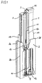
- FIG. 1 show one in different views and sections particularly advantageous embodiment of the rollover protection device according to the invention for motor vehicles in the form of any vehicle seat assigned protection system.
- This protection system consists of two Basic elements, one in the event of a crash into a support position (Fig. 1) extendable rollover body in the form of a profile bracket body 1 made of a box-like basic profile, which extends over the entire Bracket width extends, and a vehicle-fixed profile guide body 2, which also consists of a box-like basic profile, and in which the profile bracket body 1 is guided.
- the profile bracket body 1 is from the profile guide body 2 largely down to the upper section recorded, i.e. the profile guide body also serves as a cassette for the protection system.
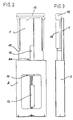
- the profile guide body 2 has both the front and the Rear wall two mounting flanges 2 a, b, c and d, with which the Protection system both on a vehicle wall and between two walls can be fastened in the vehicle. It is also conceivable for the profile guide body 2 with long screws through the holes in two in a row Flanges are inserted to screw on a vehicle wall, whereby by the tightened screws additionally ensure the stability of the profile guide body, the cassette against bending forces.
- a sliding element 6 is preferably in the groove 3 circular cross section attached.
- These sliding elements are preferably made made of plastic, especially Teflon.
- the protection system according to the invention has only one, in the middle arranged spring drive.
- a reinforced central area of the profile bracket body 1 see Fig. 4
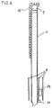
- Compression spring 8 is included, which is on its lower side on a Base plate of the profile guide body 2 supports and with its upper Side on a traverse 9, which is with the upper end face of the profile bracket body 1, covering this, is connected.
- a spring guide pin 10 fixedly attached, which is a cross-shaped Has profile and the retracted state of the profile bracket body 1, i.e. in the prestressed state of the compression spring 8, which penetrates it in a leading manner.
- This spring drive forms a in the biased state of the compression spring 8 Energy storage for the extension movement of the roll body in the form of Profile bracket body 1 in the event of a crash.
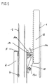
- a latch / locking arrangement is provided, the parallel to the width extension of the bracket body in a bulge 11 this bracket body is attached.
- This jack / locking arrangement has one Rack 12 and a latch 13 with biasing pawl springs 14th on.
- the rack 12 is on a narrow side of the bulge 11 on the profile bracket body 1 firmly attached, whereas the latch 13 with pawl springs 14 and a spring centering clip 14 a on one of the narrow sides opposite web 15 of the profile guide body 2, in the plane of Profile bracket body is pivoted by means of a bolt 13 a.
- the Pawl 13 has an extension 13 b, with which the Lock is releasable.
- the ratchet When the profile bracket body 1 extends, the ratchets ratchet Teeth of the rack over the pawl 13, whereas in the case of one Counter-movement of the teeth of the pawl 13, in the exemplary embodiment three teeth, remain in active engagement with the respective teeth of the rack and one Prevent movement downwards towards the rest position.
- a mechanical one Locking arrangement is provided, which unlocks in the event of a rollover Trigger system is assigned.
- This trigger system consists of one Force element 16, e.g. a pen-ejecting, pyrotechnically activated cartridge or a crash magnet, which is attached to the bottom of the guide body 2 is.
- the locking arrangement typically consists of a pawl that in the rest position with a corresponding pin in the lower area of the Profile bracket body 1 is attached, is in the locked active engagement.
- the Pawl is arranged with respect to the force element 16 so that in Rollover, triggered by a corresponding sensor in the vehicle, the force element unlocks the pawl, i.e.
- the upper part of the profile bracket body 1 is with a foam padded to prevent a possible head impact by car occupants dampen.
- the corresponding foam layer 18 comprises, in particular, from 4 can be seen, the entire front surface of the box profile Bracket body 1 and sits almost over the entire beveled narrow side of the box profile.
- the axial height of the foam casing is like this chosen that essentially the entire, from the profile guide body in extended state outstanding front surface with the foam layer 18 is covered (Fig. 3).
- a stop 17 and upper end region of the profile guide body 2 a counter stop on the Pawl attachment provided, through which the extension movement of the profile bracket body 1 is limited (Fig. 6).
Landscapes
- Engineering & Computer Science (AREA)
- Mechanical Engineering (AREA)
- Seats For Vehicles (AREA)
Description
- einer fahrzeugfest angeordneten Kassette, die als kastenförmiger biegeversteifter Profil-Führungskörper ausgebildet ist, der sich über die gesamte Kassettenhöhe erstreckt,
- einem in der Kassette ausfahrbar in Führungen gehalterten und geführten Überrollkörper in Form eines sich über die gesamte Kassettenbreite erstreckenden Profil-Bügelkörpers,
- einer Klinken-/Rastanordnung zur Selbstverriegelung der Ausfahrbewegung, und
- einem Federantriebssystem zum Ausfahren des Profil-Bügelkörpers mit am Profil-Bügelkörper angreifender, vorgespannter Druckfeder, und mit einer mechanischen Verriegelungsanordnung zum Halten der Druckfeder im vorgespannten Zustand, der ein im Überschlagfall entriegelndes Auslösesystem zugeordnet ist,
- der Profil-Bügelkörper ist kastenprofilartig, biegeversteift ausgebildet,
- an den Schmalseiten des Profil-Bügelkörpers und der Führungskörperkassette sind zueinander komplementäre Führungselemente ausgebildet,
- das Federantriebssystem weist nur eine einzige, mittig im Profil-Bügelkörper angeordnete Druckfeder auf,
- die Klinken-/Rastanordnung liegt in einer zu der Bügelbreite-seite parallelen Ebene in einer Ausbuchtung des Profil-Bügelkörpers
- der obere Teil des Profil-Bügelkörpers ist mit Schaumstoff umkleidet, und
- das Auslösesystem mit dem zugeordneten Element der Verriegelungsanordnung ist im Bodenbereich der Führungskörper-Kassette und das Gegenelement der Verriegelungsanordnung am unteren Bereich des Profil-Bügelkörpers angebracht.
- Fig. 1
- in einer perspektivischen Darstellung die Überroll-Schutzvorrichtung nach der Erfindung mit dem Profil-Bügelkörper und dem Profil-Führungskörper im ausgefahrenen Zustand des Profil-Bügelkörpers,
- Fig. 2
- eine rückwärtige Draufsicht auf die Überroll-Schutzvorrichtung nach Fig. 1,
- Fig. 3
- eine Seitenansicht des Überroll-Schutzsystems nach Fig. 1,
- Fig. 4
- einen Querschnitt durch die Überroll-Schutzvorrichtung nach Fig. 1,
- Fig. 5
- einen Ausschnitt aus Fig. 1 unter vergrößerter Darstellung der Selbstverriegelung des Profil-Bügelkörpers mittels einer Klinken-/Rastanordnung, und
- Fig. 6
- in einer Seiten-Längsschnittdarstellung den inneren Aufbau des Überroll-Schutzsystems nach Fig. 1.
- 1
- Bügelkörper
- 2
- Führungskörper
- 2 a - d
- Befestigungsflansche
- 3
- Führungsnut
- 4
- Führungsvorsprung
- 5
- Gleitelement
- 6
- Gleitelement
- 7
- Öffnung
- 8
- Druckfeder
- 9
- Traverse
- 10
- Federführungsbolzen
- 11
- Ausbuchtung
- 12
- Zahnstange
- 13
- Klinke
- 13 a
- Bolzen
- 13 b
- Fortsatz
- 14
- Klinkenfeder
- 14 a
- Zentrierclip
- 15
- Steg
- 16
- Kraftelement
- 17
- Anschlag
- 17 a
- Stift
- 18
- Schaumschicht
- 19
- Verstärkung
Claims (12)
- Überroll-Schutzvorrichtung für Kraftfahrzeuge, mit einem jedem Fahrzeugsitz zugeordneten Schutzsystem, bestehend ausgekennzeichnet durch die Merkmale:einer fahrzeugfest angeordneten Kassette (2), die als kastenförmiger biegeversteifter Profil-Führungskörper (2) ausgebildet ist, der sich über die gesamte Kassettenhöhe erstreckt,einem in der Kassette (2) ausfahrbar in Führungen gehalterten und geführten Überrollkörper in Form eines sich über die gesamte Kassettenbreite erstreckenden Profil-Bügelkörpers (1),einer Klinken-/Rastanordnung (12, 13) zur Selbstverriegelung der Ausfahrbewegung, undeinem Federantriebssystem zum Ausfahren des Profil-Bügelkörpers mit am Profil-Bügelkörper angreifender, vorgespannter Druckfeder (8), und mit einer mechanischen Verriegelungsanordnung zum Halten der Druckfeder im vorgespannten Zustand, der ein im Überschlagfall entriegelndes Auslösesystem (16) zugeordnet ist,der Profil-Bügelkörper (1) ist kastenprofilartig, biegeversteift ausgebildet,an den Schmalseiten des Profil-Bügelkörpers (1) und der Führungskörper-Kassette (2) sind zueinander komplementäre Führungselemente (3,4) ausgebildet,das Federantriebssystem weist nur eine einzige, mittig im Profil-Bügelkörper angeordnete Druckfeder (8) auf,die Klinken-/Rastanordnung (12,13) liegt in einer zu der Bügelbreite-seite parallelen Ebene in einer Ausbuchtung (11) des Profil-Bügelkörpers,der obere Teil des Profil-Bügelkörpers (1) ist mit Schaumstoff (18) umkleidet, unddas Auslösesystem (16) mit dem zugeordneten Element der Verriegelungsanordnung ist im Bodenbereich der Führungskörper-Kassette (2) und das Gegenelement der Verriegelungsanordnung am unteren Bereich des Profil-Bügelkörpers (1) angebracht.
- Überroll-Schutzvorrichtung nach Anspruch 1, dadurch gekennzeichnet, daß der Profil-Führungskörper (2) aus einem einstückigen Kastenprofil besteht.
- Überroll-Schutzvorrichtung nach Anspruch 1, dadurch gekennzeichnet, daß der Profil-Führungskörper (2) aus mindestens zwei Profilen zu einem Kastenprofil zusammengesetzt ist.
- Überroll-Schutzvorrichtung nach Anspruch 2 oder 3, dadurch gekennzeichnet, daß sowohl die Vorder- als auch die Hinterwand des Profil-Führungskörpers (2) einen Befestigungsflansch (2 a - d) aufweisen.
- Überroll-Schutzvorrichtung nach einem der Ansprüche 1 bis 4, dadurch gekennzeichnet, daß die Profile der Profil-Körper (1, 2) aus Strangpreßprofilen bestehen.
- Überroll-Schutzvorrichtung nach einem der Ansprüche 1 bis 5, dadurch gekennzeichnet, daß die Profile (1, 2) versteifende Stege und Ausbuchtungen aufweisen.
- Überroll-Schutzvorrichtung nach einem der Ansprüche 1 bis 6, dadurch gekennzeichnet, daß die Klinken-/Rastanordnung eine Zahnstange (12) und eine Rastklinke (13) mit Klinkenfeder (14) aufweisen, wobei die Zahnstange an der Schmalseite der Ausbuchtung (11) am Profilbügel-Körper (1) quer zu dessen Breite angebracht und die Rastklinke (13) mit Klinkenfedern (14) an einem gegenüberliegenden Steg (15) des Profil-Führungskörpers (2) in der Ebene des Profil-Bügelkörpers schwenkbar angelenkt ist.
- Überroll-Schutzvorrichtung nach einem der Ansprüche 1 bis 7, dadurch gekennzeichnet, daß die Führungselemente (3, 4) mit Kunststoff-Gleitelementen versehen sind.
- Überroll-Schutzvorrichtung nach Anspruch 8, dadurch gekennzeichnet, daß das Führungselement (3) am Profil-Bügelkörper (1) als axial durchgehende Nut ausgebildet ist, an der im unteren Bereich ein Kunststoff-Gleitelement (6) befestigt ist, und daß das Führungselement (4) am Profil-Führungskörper (2) als zur Nut komplementärer Vorsprung (4) ausgebildet ist, der am oberen Ende ein kappenartiges Kunststoff-Gleitelement (5) besitzt.
- Überroll-Schutzvorrichtung nach einem der Ansprüche 1 bis 9, dadurch gekennzeichnet, daß an der oberen Stirnseite des Profil-Bügelkörpers eine Traverse (9) angebracht ist, an der der obere Teil der Druckfeder (8) anliegt, und die im vorgespannten Zustand einen Federführungsbolzen (10) umgibt, der stehend ortsfest im Boden des Profil-Führungskörpers (2), an dem der untere Teil der Druckfeder (8) anliegt, angebracht ist.
- Überroll-Schutzvorrichtung nach einem der Ansprüche 1 bis 10, dadurch gekennzeichnet, daß im unteren Endbereich des Profil-Bügelkörpers (2) ein Anschlag (17) und im oberen Endbereich des Profil-Führungskörpers ein Gegenanschlag vorgesehen ist.
- Überroll-Schutzvorrichtung nach einem der Ansprüche 1 bis 11, dadurch gekennzeichnet, daß im oberen Bereich des Profil-Führungskörpers (2) an seinen Schmalseiten, zu den Schmalseiten des Profil-Bügelkörpers hin, Verstärkungselemente (19) zur Erhöhung der Längsbiegesteifigkeit im ausgefahrenen Zustand des Profil-Bügelkörpers (1) vorgesehen sind.
Applications Claiming Priority (2)
| Application Number | Priority Date | Filing Date | Title |
|---|---|---|---|
| DE19838989 | 1998-08-27 | ||
| DE19838989A DE19838989C1 (de) | 1998-08-27 | 1998-08-27 | Überroll-Schutzvorrichtung |
Publications (2)
| Publication Number | Publication Date |
|---|---|
| EP0982197A1 EP0982197A1 (de) | 2000-03-01 |
| EP0982197B1 true EP0982197B1 (de) | 2003-01-22 |
Family
ID=7878907
Family Applications (1)
| Application Number | Title | Priority Date | Filing Date |
|---|---|---|---|
| EP99110827A Expired - Lifetime EP0982197B1 (de) | 1998-08-27 | 1999-06-05 | Überrroll-Schutzvorrichtung |
Country Status (3)
| Country | Link |
|---|---|
| US (1) | US6296278B1 (de) |
| EP (1) | EP0982197B1 (de) |
| DE (2) | DE19838989C1 (de) |
Cited By (1)
| Publication number | Priority date | Publication date | Assignee | Title |
|---|---|---|---|---|
| DE102013103199A1 (de) | 2013-03-28 | 2014-10-02 | Benteler Automobiltechnik Gmbh | Lagerkassette für ein ausfahrbares Überrollschutzsystem sowie Überrollschutzsystem |
Families Citing this family (54)
| Publication number | Priority date | Publication date | Assignee | Title |
|---|---|---|---|---|
| DE19962950C1 (de) * | 1999-12-24 | 2001-03-01 | Daimler Chrysler Ag | Überrollschutzsystem für Kraftfahrzeuge |
| DE20101165U1 (de) | 2001-01-23 | 2001-06-13 | Blechformwerke Bernsbach Gmbh | Insassen-Schutzvorrichtung für ein Kraftfahrzeug |
| DE10103247C1 (de) * | 2001-01-25 | 2002-02-21 | Ise Gmbh | Überrollschutzsystem für Kraftfahrzeuge |
| DE10132421C1 (de) | 2001-07-04 | 2002-07-25 | Ise Gmbh | Überrollschutzsystem für Kraftfahrzeuge |
| ES2225703T3 (es) | 2001-08-31 | 2005-03-16 | Ise Innomotive Systems Europe Gmbh | Sistema de proteccion antivuelco para vehiculos automoviles que comprende una parte de deformacion teorica. |
| DE10223420C2 (de) * | 2001-08-31 | 2003-07-03 | Ise Gmbh | Überrollschutzsystem für Kraftfahrzeuge mit Soll-Deformationsstelle |
| DE50200577D1 (de) * | 2002-02-21 | 2004-08-05 | Ise Gmbh | Schutzvorrichtung eines PKW-Cabriolets |
| DE10209811B4 (de) * | 2002-03-06 | 2008-03-06 | Webasto Ag | Cabriolet-Fahrzeug mit Verdeckklappe und mit dieser koppelbarem Überrollbügel |
| DE10300791B3 (de) * | 2003-01-13 | 2004-05-06 | Ise Innomotive Systems Europe Gmbh | Überrollschutzsystem für Kraftfahrzeuge mit einem Überrollbügel |
| DE10300790B3 (de) * | 2003-01-13 | 2004-05-06 | Ise Innomotive Systems Europe Gmbh | Überrollschutzsystem für Kraftfahrzeuge mit einem aufstellbaren Überrollkörper |
| US7503470B2 (en) | 2003-01-28 | 2009-03-17 | Yakima Products, Inc. | Car top carrier |
| DE20303691U1 (de) * | 2003-03-07 | 2004-07-15 | Ise Innomotive Systems Europe Gmbh | Überrollschutzvorrichtung |
| DE10314975B4 (de) * | 2003-04-02 | 2006-05-24 | Ise Innomotive Systems Europe Gmbh | Überrollschutzsystem für Kraftfahrzeuge |
| DE10342488B4 (de) * | 2003-09-10 | 2006-04-27 | Ise Innomotive Systems Europe Gmbh | Überrollschutzsystem für Kraftfahrzeuge mit einem ausfahrbaren Überrollkörper |
| DE10344446B3 (de) | 2003-09-25 | 2005-02-03 | Ise Innomotive Systems Europe Gmbh | Baueinheit für die Aufnahme von zwei ausfahrbaren Überrollkörpern eines Überrollschutzsystems für Kraftfahrzeuge |
| DE10346402B3 (de) * | 2003-10-07 | 2005-01-20 | Ise Innomotive Systems Europe Gmbh | Überrollschutzsystem für Kraftfahrzeuge, das einen ausfahrbaren Überrollkörper mit kombinierter Kopfstütze aufweist |
| DE10353867B3 (de) * | 2003-11-18 | 2005-02-03 | Ise Innomotive Systems Europe Gmbh | Überrollschutzsystem für Kraftfahrzeuge mit einem ausfahrbaren Überrollkörper |
| DE10357398B3 (de) * | 2003-12-06 | 2005-04-14 | Ise Innomotive Systems Europe Gmbh | Überrollschutzsystem für Kraftfahrzeuge mit einem ausfahrbaren Überrollkörper |
| DE102004015808B3 (de) * | 2004-03-31 | 2005-03-10 | Ise Gmbh | Überrollschutzsystem für Kraftfahrzeuge mit einem ausfahrbaren Überrollkörper |
| DE102004035015B3 (de) | 2004-07-20 | 2005-12-08 | Ise Innomotive Systems Europe Gmbh | Überrollschutzsystem für Kraftfahrzeuge mit versenkbarem Dach |
| DE102005004648B3 (de) * | 2005-02-02 | 2006-03-16 | Ise Innomotive Systems Europe Gmbh | Baueinheit für die Aufnahme von zwei ausfahrbaren Überrollkörpern eines Überrollschutzsystems für Kraftfahrzeuge |
| DE102006002476B4 (de) * | 2005-06-22 | 2009-03-19 | Wilhelm Karmann Gmbh | Überrollschutzsystem für ein Kraftfahrzeug |
| DE102006000909B4 (de) * | 2005-06-22 | 2009-06-25 | Wilhelm Karmann Gmbh | Überrollschutzsystem für ein Cabriolet-Fahrzeug mit gekrümmtem Überrollkörper |
| DE102005028964B4 (de) * | 2005-06-22 | 2007-11-08 | Wilhelm Karmann Gmbh | Überrollschutzsystem für ein Kraftfahrzeug |
| DE102005028879B4 (de) * | 2005-06-22 | 2008-01-03 | Wilhelm Karmann Gmbh | Überrollschutzsystem für ein Kraftfahrzeug |
| DE102006028664B4 (de) * | 2005-06-22 | 2009-03-05 | Wilhelm Karmann Gmbh | Überrollschutzsystem für ein Kraftfahrzeug |
| DE102005028966B4 (de) * | 2005-06-22 | 2009-04-02 | Wilhelm Karmann Gmbh | Kraftfahrzeug mit einem Überrollschutzsystem an einer Fahrzeugquerwand |
| DE102005028929B4 (de) * | 2005-06-22 | 2009-04-09 | Wilhelm Karmann Gmbh | Bauteilgruppe für ein Cabriolet-Kraftfahrzeug |
| DE102005029253B4 (de) * | 2005-06-23 | 2009-04-02 | Wilhelm Karmann Gmbh | Cabriolet mit einem Überrollschutzsystem |
| DE102005029451A1 (de) * | 2005-06-24 | 2007-01-04 | Wilhelm Karmann Gmbh | Kraftfahrzeug mit einem Überrollschutzsystem |
| ATE460318T1 (de) * | 2005-07-18 | 2010-03-15 | Norsk Hydro As | Überrollschutzsystem |
| US7690684B2 (en) | 2005-09-07 | 2010-04-06 | Honda Motor Co., Ltd. | Vehicle occupant protection apparatus and startup method of same |
| US20070205240A1 (en) * | 2005-10-21 | 2007-09-06 | Jeff Castro | Vehicle top carriers |
| US20070164066A1 (en) * | 2005-11-08 | 2007-07-19 | Peter Jones | Vehicle top carrier with gull wing doors |
| US7384067B2 (en) | 2006-01-06 | 2008-06-10 | Autoliv Asp, Inc. | Rollover protection for motor vehicles |
| DE102006048085B4 (de) * | 2006-10-10 | 2009-05-07 | Ise Automotive Gmbh | Überrollschutzsystem für Kraftfahrzeuge mit mindestens einem aktiv aufstellbaren Überrollbügel |
| GB0622172D0 (en) * | 2006-11-07 | 2006-12-20 | Ford Global Tech Llc | An actuatin mechanism for a stowable roof panel |
| DE102007005517B4 (de) | 2007-02-03 | 2010-09-30 | Ise Automotive Gmbh | Überrollschutzsystem für Kraftfahrzeuge mit einem aktiv aufstellbaren Überrollkörper mit integriertem Deformationselement |
| DE102007042882A1 (de) | 2007-09-08 | 2009-03-12 | Wilhelm Karmann Gmbh | Führungselement zur Führung zweier relativ zueinander bewegbarer Bauelemente, insbesondere einer Überrollschutzeinrichtung eines Cabriolet-Fahrzeugs |
| DE102008018483A1 (de) | 2008-04-11 | 2009-10-29 | Ise Automotive Gmbh | Überrollschutzsystem für Kraftfahrzeuge |
| DE102008002138B4 (de) | 2008-05-30 | 2012-09-06 | Ise Automotive Gmbh | Überrollschutzsystem für Personenkraftwagen |
| DE202008010941U1 (de) | 2008-08-16 | 2008-10-23 | Ise Automotive Gmbh | Überrollschutzsystem für Kraftfahrzeuge |
| DE102008041780B4 (de) | 2008-09-03 | 2012-04-12 | Ise Automotive Gmbh | Überrollschutzsystem für Kraftfahrzeuge |
| DE102008054890B3 (de) * | 2008-12-18 | 2010-07-01 | Ise Automotive Gmbh | Verfahren zur Herstellung eines ausfahrbaren Überrollkörpers |
| EP2239166B1 (de) | 2010-01-19 | 2013-05-29 | ISE Automotive GmbH | Überrollschutzsystem für Kraftfahrzeuge |
| US7997616B1 (en) | 2010-02-18 | 2011-08-16 | Ise Automotive Gmbh | Rollover protection system for automobiles |
| DE102010036781A1 (de) * | 2010-05-04 | 2011-11-10 | Alutech Gesellschaft M.B.H. | Verriegelungsvorrichtung für ein Überrollschutzsystem und Überrollschutzsystem mit einer Verriegelungsvorrichtung |
| WO2012047452A1 (en) | 2010-10-05 | 2012-04-12 | Yakima Products, Inc. | Stabilized cargo box for a vehicle rack system |
| EP2394867B1 (de) * | 2011-05-03 | 2015-03-04 | Metalsa Automotive GmbH | Überrollschutzsystem für Kraftfahrzeuge |
| WO2014022437A2 (en) | 2012-07-30 | 2014-02-06 | Yakima Innovation Development Corporation | Carrier for a vehicle |
| DE102012018958A1 (de) * | 2012-09-26 | 2014-03-27 | Benteler Automobiltechnik Gmbh | Kraftfahrzeug mit Überrollschutzsystem |
| RU2548818C1 (ru) * | 2014-04-01 | 2015-04-20 | Федеральное Государственное Бюджетное Образовательное Учреждение Высшего Профессионального Образования "Донской Государственный Технический Университет" (Дгту) | Устройство для повышения прочности кузова транспортного средства при опрокидывании |
| US9598032B1 (en) * | 2015-12-04 | 2017-03-21 | Ford Global Technologies, Llc | Wheel rotation blocking apparatus |
| US11325539B2 (en) | 2019-03-08 | 2022-05-10 | Yakima Products, Inc. | Fishing gear carrier box |
Family Cites Families (10)
| Publication number | Priority date | Publication date | Assignee | Title |
|---|---|---|---|---|
| DE3922509A1 (de) * | 1989-07-08 | 1991-01-17 | Daimler Benz Ag | Kopfstuetze fuer ruecksitze |
| DE3927265C3 (de) * | 1989-08-18 | 2003-03-27 | Ise Gmbh | Insassenschutzeinrichtung für Kraftfahrzeuge mit einem Überrollbügel |
| DE4100506C1 (de) * | 1991-01-10 | 1992-05-21 | Mercedes-Benz Aktiengesellschaft, 7000 Stuttgart, De | |
| EP0729867B1 (de) * | 1993-05-03 | 1999-06-02 | Bayerische Motoren Werke Aktiengesellschaft, Patentabteilung AJ-3 | Überrollschutz-Vorrichtung für ein Kraftfahrzeug |
| US5626361A (en) * | 1993-05-03 | 1997-05-06 | Bayerische Motoren Werke Ag | Roll-over protection arrangement for a motor vehicle |
| DE4314538C3 (de) * | 1993-05-03 | 2000-11-09 | Bayerische Motoren Werke Ag | Überrollschutz-Vorrichtung für ein Kraftfahrzeug |
| DE4345524C2 (de) * | 1993-08-03 | 2002-06-13 | Ise Gmbh | Überrollschutzsystem |
| DE4342402C2 (de) * | 1993-12-13 | 2000-08-10 | Ise Gmbh | Antriebs- und Riegelmechanismus für einen geradlinig ausfahrbaren Überrollbügel |
| DE19501584C2 (de) * | 1995-01-20 | 2002-06-13 | Porsche Ag | Kraftfahrzeug, insbesondere Cabriolet |
| DE19523790C2 (de) * | 1995-07-04 | 2000-07-20 | Ise Gmbh | Ausfahrbarer Überrollbügel |
-
1998
- 1998-08-27 DE DE19838989A patent/DE19838989C1/de not_active Expired - Fee Related
-
1999
- 1999-06-05 DE DE59904078T patent/DE59904078D1/de not_active Expired - Lifetime
- 1999-06-05 EP EP99110827A patent/EP0982197B1/de not_active Expired - Lifetime
- 1999-08-20 US US09/368,768 patent/US6296278B1/en not_active Expired - Fee Related
Cited By (1)
| Publication number | Priority date | Publication date | Assignee | Title |
|---|---|---|---|---|
| DE102013103199A1 (de) | 2013-03-28 | 2014-10-02 | Benteler Automobiltechnik Gmbh | Lagerkassette für ein ausfahrbares Überrollschutzsystem sowie Überrollschutzsystem |
Also Published As
| Publication number | Publication date |
|---|---|
| DE59904078D1 (de) | 2003-02-27 |
| US6296278B1 (en) | 2001-10-02 |
| EP0982197A1 (de) | 2000-03-01 |
| DE19838989C1 (de) | 1999-11-11 |
Similar Documents
| Publication | Publication Date | Title |
|---|---|---|
| DE19838989C1 (de) | Überroll-Schutzvorrichtung | |
| EP3964405B1 (de) | Lasttragendes strukturteil für einen fahrzeugsitz | |
| DE4100506C1 (de) | ||
| DE4314538C2 (de) | Überrollschutz-Vorrichtung für ein Kraftfahrzeug | |
| DE19651092A1 (de) | Sicherheitsgurtvorrichtung für ein Fahrzeug | |
| EP1288079B1 (de) | Überrollschutzsystem für Kraftfahrzeuge mit Soll-Deformationsstelle | |
| DE7145043U (de) | Fahrzeugaufbau mit verstaerkungsteil zum schutz der fahrzeuginsassen bei unfaellen | |
| DE19750457C2 (de) | Ausfahrbarer Überrollbügel für Kraftfahrzeuge | |
| DE102021118922A1 (de) | Gurtführung | |
| EP1182097B1 (de) | Überrollschutzsystem | |
| EP1095823B1 (de) | Überrollschutzsystem für Kraftfahrzeuge | |
| DE102006028664B4 (de) | Überrollschutzsystem für ein Kraftfahrzeug | |
| EP1227011B1 (de) | Überrollschutzsystem für Kraftfahrzeuge | |
| EP1955908B1 (de) | Überrollschutzsystem für Kraftfahrzeuge mit einem sensorgesteuert aktiv aufstellbaren Überrollkörper | |
| DE19806607B4 (de) | Verformungsschutzeinrichtung für einen in einem Kraftfahrzeug angeordneten Kraftstofftank | |
| DE19614141C2 (de) | Kinderschutz für Kraftfahrzeuge | |
| EP1122121B1 (de) | Transportbehälter-Einrichtung für den Einbau in Kraftfahrzeuge, wie z.B. Durchladeeinrichtung | |
| DE102009006876B4 (de) | Laderaumabdeckung | |
| EP1911634A1 (de) | Überrollschutzsystem für Kraftfahrzeuge mit mindestens einem aktiv aufstellbaren Überrollbügel | |
| DE102005028879B4 (de) | Überrollschutzsystem für ein Kraftfahrzeug | |
| EP1842736B1 (de) | Überrollschutzsystem für Kraftfahrzeuge mit mindestens einem aktiv aufstellbaren Überrollbügel | |
| DE102005028966B4 (de) | Kraftfahrzeug mit einem Überrollschutzsystem an einer Fahrzeugquerwand | |
| DE102008042528B4 (de) | Überrollschutzsystem für Kraftfahrzeuge mit Montagekassette | |
| EP1227012B1 (de) | Überrollschutzsystem für Kraftfahrzeuge | |
| DE102009021830A1 (de) | Sicherheitseinrichtung für Kraftfahrzeuge, insbesondere Kraftfahrzeug-Sitzlehnen, und Kraftfahrzeug mit einer derartigen Sicherheitseinrichtung |
Legal Events
| Date | Code | Title | Description |
|---|---|---|---|
| PUAI | Public reference made under article 153(3) epc to a published international application that has entered the european phase |
Free format text: ORIGINAL CODE: 0009012 |
|
| AK | Designated contracting states |
Kind code of ref document: A1 Designated state(s): DE FR GB IT SE |
|
| AX | Request for extension of the european patent |
Free format text: AL;LT;LV;MK;RO;SI |
|
| 17P | Request for examination filed |
Effective date: 20000509 |
|
| AKX | Designation fees paid |
Free format text: DE FR GB IT SE |
|
| GRAH | Despatch of communication of intention to grant a patent |
Free format text: ORIGINAL CODE: EPIDOS IGRA |
|
| GRAH | Despatch of communication of intention to grant a patent |
Free format text: ORIGINAL CODE: EPIDOS IGRA |
|
| GRAA | (expected) grant |
Free format text: ORIGINAL CODE: 0009210 |
|
| AK | Designated contracting states |
Kind code of ref document: B1 Designated state(s): DE FR GB IT SE |
|
| REG | Reference to a national code |
Ref country code: GB Ref legal event code: FG4D Free format text: NOT ENGLISH |
|
| REF | Corresponds to: |
Ref document number: 59904078 Country of ref document: DE Date of ref document: 20030227 Kind code of ref document: P |
|
| REG | Reference to a national code |
Ref country code: SE Ref legal event code: TRGR |
|
| GBT | Gb: translation of ep patent filed (gb section 77(6)(a)/1977) |
Effective date: 20030519 |
|
| ET | Fr: translation filed | ||
| PLBE | No opposition filed within time limit |
Free format text: ORIGINAL CODE: 0009261 |
|
| STAA | Information on the status of an ep patent application or granted ep patent |
Free format text: STATUS: NO OPPOSITION FILED WITHIN TIME LIMIT |
|
| 26N | No opposition filed |
Effective date: 20031023 |
|
| PGFP | Annual fee paid to national office [announced via postgrant information from national office to epo] |
Ref country code: IT Payment date: 20080625 Year of fee payment: 10 |
|
| PGFP | Annual fee paid to national office [announced via postgrant information from national office to epo] |
Ref country code: SE Payment date: 20080624 Year of fee payment: 10 |
|
| PGFP | Annual fee paid to national office [announced via postgrant information from national office to epo] |
Ref country code: FR Payment date: 20090618 Year of fee payment: 11 |
|
| PGFP | Annual fee paid to national office [announced via postgrant information from national office to epo] |
Ref country code: GB Payment date: 20090623 Year of fee payment: 11 |
|
| GBPC | Gb: european patent ceased through non-payment of renewal fee |
Effective date: 20100605 |
|
| REG | Reference to a national code |
Ref country code: FR Ref legal event code: ST Effective date: 20110228 |
|
| PG25 | Lapsed in a contracting state [announced via postgrant information from national office to epo] |
Ref country code: IT Free format text: LAPSE BECAUSE OF NON-PAYMENT OF DUE FEES Effective date: 20090605 |
|
| PG25 | Lapsed in a contracting state [announced via postgrant information from national office to epo] |
Ref country code: SE Free format text: LAPSE BECAUSE OF NON-PAYMENT OF DUE FEES Effective date: 20090606 Ref country code: FR Free format text: LAPSE BECAUSE OF NON-PAYMENT OF DUE FEES Effective date: 20100630 |
|
| PG25 | Lapsed in a contracting state [announced via postgrant information from national office to epo] |
Ref country code: GB Free format text: LAPSE BECAUSE OF NON-PAYMENT OF DUE FEES Effective date: 20100605 |
|
| REG | Reference to a national code |
Ref country code: DE Ref legal event code: R082 Ref document number: 59904078 Country of ref document: DE Representative=s name: KALKOFF & PARTNER PATENTANWAELTE, DE |
|
| REG | Reference to a national code |
Ref country code: DE Ref legal event code: R082 Ref document number: 59904078 Country of ref document: DE Representative=s name: REBBEREH, CORNELIA, DIPL.-ING., DE Effective date: 20130812 Ref country code: DE Ref legal event code: R082 Ref document number: 59904078 Country of ref document: DE Representative=s name: KALKOFF & PARTNER PATENTANWAELTE, DE Effective date: 20130812 Ref country code: DE Ref legal event code: R081 Ref document number: 59904078 Country of ref document: DE Owner name: METALSA AUTOMOTIVE GMBH, DE Free format text: FORMER OWNER: ISE AUTOMOTIVE GMBH, 51702 BERGNEUSTADT, DE Effective date: 20130812 |
|
| REG | Reference to a national code |
Ref country code: DE Ref legal event code: R082 Ref document number: 59904078 Country of ref document: DE Representative=s name: REBBEREH, CORNELIA, DIPL.-ING., DE |
|
| PGFP | Annual fee paid to national office [announced via postgrant information from national office to epo] |
Ref country code: DE Payment date: 20180601 Year of fee payment: 20 |
|
| REG | Reference to a national code |
Ref country code: DE Ref legal event code: R071 Ref document number: 59904078 Country of ref document: DE |