EP0982501B1 - Extracteur d'air encastrable - Google Patents
Extracteur d'air encastrable Download PDFInfo
- Publication number
- EP0982501B1 EP0982501B1 EP98950118A EP98950118A EP0982501B1 EP 0982501 B1 EP0982501 B1 EP 0982501B1 EP 98950118 A EP98950118 A EP 98950118A EP 98950118 A EP98950118 A EP 98950118A EP 0982501 B1 EP0982501 B1 EP 0982501B1
- Authority
- EP
- European Patent Office
- Prior art keywords
- cylindrical
- cylindrical part
- laminar
- ring
- extractor
- Prior art date
- Legal status (The legal status is an assumption and is not a legal conclusion. Google has not performed a legal analysis and makes no representation as to the accuracy of the status listed.)
- Expired - Lifetime
Links
- 238000005192 partition Methods 0.000 claims description 6
- 241000935974 Paralichthys dentatus Species 0.000 claims description 4
- 239000011810 insulating material Substances 0.000 claims description 3
- 230000001681 protective effect Effects 0.000 description 10
- 238000009434 installation Methods 0.000 description 4
- 239000000463 material Substances 0.000 description 4
- 239000011521 glass Substances 0.000 description 3
- 238000004873 anchoring Methods 0.000 description 2
- 238000000034 method Methods 0.000 description 2
- 238000009423 ventilation Methods 0.000 description 2
- 241000242541 Trematoda Species 0.000 description 1
- 230000006978 adaptation Effects 0.000 description 1
- 239000004020 conductor Substances 0.000 description 1
- 238000001514 detection method Methods 0.000 description 1
- 238000005553 drilling Methods 0.000 description 1
- 238000000605 extraction Methods 0.000 description 1
- 238000003780 insertion Methods 0.000 description 1
- 230000037431 insertion Effects 0.000 description 1
- 230000035515 penetration Effects 0.000 description 1
- IOVGROKTTNBUGK-SJCJKPOMSA-N ritodrine Chemical group N([C@@H](C)[C@H](O)C=1C=CC(O)=CC=1)CCC1=CC=C(O)C=C1 IOVGROKTTNBUGK-SJCJKPOMSA-N 0.000 description 1
- 239000011435 rock Substances 0.000 description 1
- 230000003068 static effect Effects 0.000 description 1
- 238000005406 washing Methods 0.000 description 1
Images

Classifications
-
- F—MECHANICAL ENGINEERING; LIGHTING; HEATING; WEAPONS; BLASTING
- F04—POSITIVE - DISPLACEMENT MACHINES FOR LIQUIDS; PUMPS FOR LIQUIDS OR ELASTIC FLUIDS
- F04D—NON-POSITIVE-DISPLACEMENT PUMPS
- F04D25/00—Pumping installations or systems
- F04D25/02—Units comprising pumps and their driving means
- F04D25/08—Units comprising pumps and their driving means the working fluid being air, e.g. for ventilation
- F04D25/12—Units comprising pumps and their driving means the working fluid being air, e.g. for ventilation the unit being adapted for mounting in apertures
Definitions
- the present invention concerns an air extractor adaptable for building in, of the type of those which comprise: a supporting casing of insulating material, an impeller with blades working as an axial fan, an electric motor and an electronic circuit.
- German patent DE 36 10 685 C 1 describes an invention which relates to a ventilator for installation in an opening of a window or of the wall with a casing essentially in the form of a shell, in which an electromotor is installed with a fan on the upper part of the motor shaft, and with a protective piece which covers the suction or discharge part of the casing, which can be joined to the casing, it has an essentially square cross section and allows air to pass.
- the protective piece can rotate with limitations next to an intermediate piece.
- the intermediate piece has some plug pins which can be plugged into some female sockets of a connection strip which is fixed to the casing. The plug-in connection can only take place in the predetermined rotating position of the intermediate piece.
- the electric components of the protective piece are connected with the plug pins by means of some connecting wires.
- the protective piece can be positioned independently of the assembly position of the casing in the opening of the window or of the wall without endangering the interconnection between the protective piece and the connection strip.
- German publication DE 3711720 Al the invention is made known which relates to a ventilator for installation in an opening of a window or of the wall with a casing essentially in the form of a shell, in which an electromotor is installed with a fan on the upper part of the motor shaft, and with some protective pieces which cover the suction or discharge part of the casing, which can be joined to the casing, they have an essentially square cross section and allow the air to pass.
- the emplacement of the protective piece without visible fastening elements with the possibility of universal positioning of the protective piece on the casing is achieved because the protective piece and a part of the casing have respectively on their mutually opposing parts, one fitting over the other, some unions by embedding and/or bayonet-fitting with some coincident elements facing each other, and by means of these they can be joined to each other, and in that with the unions produced by embedding and/or bayonet-fitting the piece is housed in the opposing part of the casing in the plane of the suction or discharge part so that it can rotate with limitations.
- the present invention is an air extractor adaptable for buildings, which comprises a supporting casing of insulating material, which consists of a cylindrical part, and a laminar part in integral arrangement, so that the laminar part is essentially at right angles to the axis of the cylindrical part, said cylindrical part having a cylindrical body joined to the cylindrical part by radial arms, said cylindrical body determining two recesses, one directed towards the rear part which houses the electronic circuit and the other directed towards the rear rear part which houses the electric motor, there remaining between the cylindrical body and cylindrical part a passage for the air, characterized in that the cylindrical part is provided with embossed projections between which are determined a number of helicoidal spaces which act together with a helicoidal rib practised on the inside cylindrical face of a ring, so that the assembly by screwing of said ring on the cylindrical part mentioned makes it possible to graduate the distance of said ring with the laminar part and in that the laminar part has on its perimeter an elastic section that extends beyond said perimeter, capable of being anchored in
- the extractor of the present invention has at least two of the radial arms, diametrically opposite, have each a fork which determines an open space in the cylindrical part, being closed by a front partition, which is traversed by a screw which also traverses a folded fluke capable of tilting back and forth, and is screwed into a piece in form of a prism.
- the extractor of the present invention allows, in the manner priorly detailed, the possibility of rapid means for its installation in ceilings as well as walls, and also laminar media such as glass and panels.
- Fig. 1 is a front view, exploded in perspective, of the extractor object of the present invention.
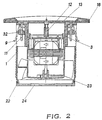
- Fig. 2 is a diametrical cross section of the extractor in accordance with Fig. 1, conveniently assembled.
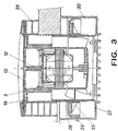
- Fig. 3 is a diametrical cross section of same extractor, showing also elements related with its adaptation to a window of any standard thickness.
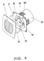
- Fig. 4 is a front view, exploded in perspective, of the supporting casing of the extractor and cover, showing schematically the system for mounting.
- the extractor device object of the invention comprises, in the first place, a supporting casing which is preferentially moulded in a single piece from a suitable plastic material.
- This supporting casing is in the form of a cylindrical part 1, and a laminar part 2, the orientation of which is perpendicular to the hypothetical axis of the cylindrical part; preferentially it is square in shape though its sides are slightly concave.
- the cylindrical part 1 is serves for the housing of the assembly formed by the impeller 6 fitted with blades, that acts as axial ventilator, the electric motor 5 and the electronic circuit 7, useful for different applications. Inside said cylindrical part 1 is also to be found a cavity which is occupied partly by a cylindrical body 3, preferably moulded in single piece with the assembly, located coaxially with respect to the cylindrical part 1; from the foregoing, it is appreciated that a passage is left between the cylindrical part 1 and the cylindrical body 3.
- This cylindrical body 3 is connected by means of a number of radial arms 4 with the cylindrical part 1.
- the electric motor 5 is housed, practically entirely, inside the cylindrical body 3 and the impeller 6 is fixed directly onto the shaft of the electric motor 5.
- the impeller 6 be moulded in a single piece from a suitable plastic material in order to partly cover the electric motor, thereby eliminating any possibility of establishing contact with parts of the extractor that may be electrically live, even when using the feeler gauge required for the tests dictated by the electrical safety standard.
- the cylindrical body 3 consists of two inverted housings, one for the aforementioned electric motor and another situated centrally to hold the different electronic circuits, such as the timing circuit and the circuit 7 equipped with a humidity detector (Fig. 1).
- This housing likewise permits the mounting of a standard connection strip in the case of a standard extractor, or the mounting of the electronic circuits in a quick and secure manner, retaining them in position by pliable pawls inside the housing, which provides the benefit of permitting the housing of all connections to be made on installation without taking up space on the outside and permitting the use of an extremely flat cover 8, wherein an innovation is introduced in the size of the extractors commercially available to date, permitting the invention to be housed almost entirely inside ducting pipes, in holes or other recesses made in walls, windows or ceilings for this purpose.
- Each space also incorporates an essentially prismatic part 32 through which screw 9 can run; this piece 32 is fitted in such a manner it cannot turn in the space mentioned; thus, when screw 11 is turned, the piece 32 is moved towards the outside partition and, as a consequence, produces the tilting of the fluke 9 towards the outside of the cylindrical body 3, the result being its free ends overshoot the space and can bite into a body surrounding the cylindrical part 1, the flukes 9 being anchored into the walls where it is to be installed, fixing the extractor in place in a quick and clean fashion.
- the radial arms have been designed as a thin flat shape whereby they merely act as guide vanes for the air flow, achieving maximum advantage of the circular cross section for said air flow, however they can be implemented with other shapes and sections.
- a central pillar 12 can be observed, to which the protective cover 13 is screwed, preferably moulded as a single piece, which can close the housing of the electronic circuitry; preferentially it is round in shape, but other forms can be taken, with arms arranged at 180° in order to fit into the channels made in the radial arms for the passage of cables and be able to mount the cover 13 securely.
- a number of small slots 14 can be made permitting thereby the penetration of humidity for detection without failing to comply with any tests of the standard.
- a drill hole 15 for the case of incorporating a humidity detector, with the purpose of showing a light emitting diode (LED) to indicate the operational state.
- a front cover 8 can be pressure-fitted and held in place on the front face of the supporting casing; this can be done, for example, by means of a device 31 with non-return anchoring, its release only being possible with the assistance of a screwdriver tip.
- Said cover preferentially slightly convex or arched, provided with a large central opening 17, which constitutes the entrance for the suction or intake of air to the extractor, is covered by a grill 18, preferably moulded as a single piece with the assembly, framed by the inside part of the opening 17 by a lip 19 (Fig. 3), which is prepared for fitting on the free edge of the inside diameter of the laminar part 2 of the supporting casing; these elements fit together in an extremely shallow configuration.
- the outlet for the conductors corresponding to the power supply of the device can be led through the slight gap 20 provided for this purpose in the laminar part or flat leaf 2, or it can also be done laterally though the front cover 8, provided with a notch 21 in its side wall.
- the cylindrical part 1 there are two rectangular slots for the anchoring of a first ring 22, which in turn is provided with fixing pawls and drill holes which run through the thickness of the first ring 22 in order to incorporate two semi-circular fins 24, the function of which is to block the passage of return air, with the help of two weak springs inserted on the axis of rotation of the fins, making it possible for air to pass outwards only.
- the extractor as well as to a wall or ceiling, can be applied to a window pane; to this end, an optional kit is prepar ed consisting of the second ring 25, a frame 26, a front cover 27 and an offsetting frame 28, these being moulded from a plastic material.
- the second ring 25 has incorporated on its inside diameter a screw thread which adapts to the threaded sections of the cylindrical part 1 of the supporting casing whereby when screwed onto said part the kit frame 26 is trapped against the glass and by displacing the inside face of the support leaving an offsetting section between the two elements mentioned which shall depend on the thickness of the glass. Therefore, in both cases the distance is offset with the offsetting frame 28 which being nestable can be built up to the thickness required.
- the front cover of the kit explained is press-fitted, and held in position by means of a screw 29, preferentially moulded in a single piece, which takes the shape of a square tray, having side walls 30, arranged to fit on its free edge into a recess which runs parallel to the edge of the outside partition of the frame 26, with a retaining web on its side opposite to the screw socket.
- the offsetting frame is an independent piece preferably square in shape, following the external profile of the front cover 8, moulded from plastic material, which with a slot following the outside profile on one side and a rib standing out on the other face, makes it possible to assemble various frames until the desired offsetting height is reached.
Landscapes
- Engineering & Computer Science (AREA)
- Mechanical Engineering (AREA)
- General Engineering & Computer Science (AREA)
- Structures Of Non-Positive Displacement Pumps (AREA)
Claims (2)
- Extracteur d'air adaptable à des bâtiments, qui comporte un carter de support d'un matériau isolant qui est constitué d'une partie cylindrique (1) et d'une partie laminaire (2) sous forme d'un arrangement solidaire, afin que la partie laminaire (2) soit pratiquement perpendiculaire à l'axe de la partie cylindrique (1), la partie cylindrique (1) ayant un corps cylindrique (3) raccordé à la partie cylindrique (1) par des bras radiaux (4), le corps cylindrique (3) délimitant deux cavités dont l'une est dirigée vers la partie arrière qui loge le circuit électronique (7) et l'autre est dirigée vers la partie arrière qui loge le moteur électrique (5), un passage pour l'air restant entre le corps cylindrique et la partie cylindrique, caractérisé en ce que la partie cylindrique (1) a des saillies entre lesquelles sont déterminés un certain nombre d'espaces hélicoïdaux qui forment ensemble une nervure hélicoïdale disposée à la face cylindrique interne d'un anneau (25) afin que l'assemblage par vissage de l'anneau (25) sur la partie cylindrique précitée (1) rende possible la gradation de la distance de l'anneau (25) sur la partie laminaire (2), et en ce que la partie laminaire (2) a à sa périphérie un tronçon élastique (31) qui s'étend au-delà de la périphérie et qui peut être fixé dans une gorge (21) du bord latéral du couvercle avant (8) qui a la forme d'une mince cuvette et qui a une ouverture (17) pour le passage d'air.
- Extracteur selon la revendication 1, caractérisé en ce que deux au moins des bras radiaux (4) diamétralement opposés ont chacun une fourche qui délimite un espace ouvert dans la partie cylindrique (1) et qui est fermé par une cloison avant qui est traversée par une vis (11) qui passe aussi dans une aile pliée (9) qui peut basculer vers l'avant et vers l'arrière et est vissée sur une pièce (32) en forme de prisme.
Applications Claiming Priority (3)
| Application Number | Priority Date | Filing Date | Title |
|---|---|---|---|
| ES9702753U ES1038510Y (es) | 1997-10-27 | 1997-10-27 | Extractor de aire encastrable. |
| ES9702753U | 1997-10-27 | ||
| PCT/ES1998/000290 WO1999022145A1 (fr) | 1997-10-27 | 1998-10-27 | Extracteur d'air encastrable |
Publications (2)
| Publication Number | Publication Date |
|---|---|
| EP0982501A1 EP0982501A1 (fr) | 2000-03-01 |
| EP0982501B1 true EP0982501B1 (fr) | 2003-12-10 |
Family
ID=8301705
Family Applications (1)
| Application Number | Title | Priority Date | Filing Date |
|---|---|---|---|
| EP98950118A Expired - Lifetime EP0982501B1 (fr) | 1997-10-27 | 1998-10-27 | Extracteur d'air encastrable |
Country Status (4)
| Country | Link |
|---|---|
| EP (1) | EP0982501B1 (fr) |
| DE (1) | DE69820434T2 (fr) |
| ES (1) | ES1038510Y (fr) |
| WO (1) | WO1999022145A1 (fr) |
Families Citing this family (6)
| Publication number | Priority date | Publication date | Assignee | Title |
|---|---|---|---|---|
| ES2155362B1 (es) * | 1998-12-16 | 2002-03-16 | Soler & Palau | Perfeccionamientos introducidos en los extractores ultracompactos para baños. |
| ES2212720B1 (es) * | 2002-05-22 | 2005-10-01 | Cata Electrodomesticos, S.L | Extractor de aire con tapa frontal extraible. |
| ES2212719B1 (es) * | 2002-05-22 | 2005-10-01 | Cata Electrodomesticos, S.L | Extractor de aire de apertura automatica. |
| ES2251878B1 (es) * | 2004-10-26 | 2007-02-16 | SOLER & PALAU, S.A. | Extractor de aire de flujo axial para baños y similares. |
| ITVR20110241A1 (it) * | 2011-12-30 | 2013-07-01 | Everel Group S P A | Motore per l'azionamento di ventole d'aspirazione |
| DE202012103921U1 (de) | 2012-10-12 | 2014-01-16 | Ebm-Papst St. Georgen Gmbh & Co. Kg | Montageelement zur Befestigung eines Lüftergehäuses und Lüftergehäuse |
Family Cites Families (6)
| Publication number | Priority date | Publication date | Assignee | Title |
|---|---|---|---|---|
| GB1054512A (fr) * | 1900-01-01 | |||
| GB910475A (en) * | 1961-01-05 | 1962-11-14 | Vent Axia Ltd | Improvements in and relating to ventilating fans |
| US4142844A (en) * | 1977-05-31 | 1979-03-06 | Allware Agencies Ltd. | Fan blade assemblies for box fans |
| DE3610685C1 (en) * | 1986-03-29 | 1987-05-14 | Loh Kg Ritto Werk | Fan |
| DE3711720C2 (de) * | 1987-04-07 | 1993-11-04 | Loh Kg Ritto Werk | Ventilator |
| GB2240621B (en) * | 1990-01-31 | 1993-10-20 | Toshiba Kk | Ventilating fan |
-
1997
- 1997-10-27 ES ES9702753U patent/ES1038510Y/es not_active Expired - Fee Related
-
1998
- 1998-10-27 EP EP98950118A patent/EP0982501B1/fr not_active Expired - Lifetime
- 1998-10-27 WO PCT/ES1998/000290 patent/WO1999022145A1/fr not_active Ceased
- 1998-10-27 DE DE69820434T patent/DE69820434T2/de not_active Expired - Fee Related
Also Published As
| Publication number | Publication date |
|---|---|
| ES1038510U (es) | 1998-07-01 |
| EP0982501A1 (fr) | 2000-03-01 |
| DE69820434D1 (de) | 2004-01-22 |
| WO1999022145A1 (fr) | 1999-05-06 |
| ES1038510Y (es) | 1999-01-01 |
| DE69820434T2 (de) | 2004-10-07 |
Similar Documents
| Publication | Publication Date | Title |
|---|---|---|
| CN100510508C (zh) | 一种用于建筑物接线盒的条件响应照明器材 | |
| CN101171728B (zh) | 用于墙式安装电气设备的支撑框架 | |
| BRPI0503053A (pt) | aparelho para conexão em uma fonte elétrica | |
| EP0982501A1 (fr) | Extracteur d'air encastrable | |
| KR101985811B1 (ko) | 공동주택 건축물의 전기케이블 지지구 | |
| JP3297584B2 (ja) | 換気扇 | |
| US6774308B1 (en) | Wire termination box assembly and associated method of installation | |
| JP3819496B2 (ja) | 空気調和機 | |
| EP2926055A1 (fr) | Ventilateur avec kit pour fenêtre | |
| CN110178313A (zh) | 通信适配器安装装置 | |
| EP1008762A2 (fr) | Ventilateur électrique et connecteur électrique | |
| JP3177884B2 (ja) | 配線器具設置装置、保持プレート、保持プレート部材、配線器具及びシール部材 | |
| JPH07190439A (ja) | パイプ用ファン | |
| WO2021207784A1 (fr) | Ensemble de signalisation | |
| EP1729068A1 (fr) | Unité combinée de ventilation et lumière | |
| JP6676157B2 (ja) | 端子台および換気扇 | |
| JP2002332994A (ja) | 換気扇 | |
| JP2001061213A (ja) | シール部材 | |
| CN215491863U (zh) | 一种壁挂式温湿度计壳体结构 | |
| KR100564294B1 (ko) | 천장 전기 단자함 | |
| JPH0365633B2 (fr) | ||
| JP3368707B2 (ja) | 空気調和装置 | |
| JPS6328344Y2 (fr) | ||
| JP3731102B2 (ja) | 換気装置 | |
| JP2010107149A (ja) | 換気装置 |
Legal Events
| Date | Code | Title | Description |
|---|---|---|---|
| PUAI | Public reference made under article 153(3) epc to a published international application that has entered the european phase |
Free format text: ORIGINAL CODE: 0009012 |
|
| 17P | Request for examination filed |
Effective date: 19990614 |
|
| AK | Designated contracting states |
Kind code of ref document: A1 Designated state(s): DE FR GB IT NL |
|
| 17Q | First examination report despatched |
Effective date: 20020905 |
|
| GRAH | Despatch of communication of intention to grant a patent |
Free format text: ORIGINAL CODE: EPIDOS IGRA |
|
| GRAH | Despatch of communication of intention to grant a patent |
Free format text: ORIGINAL CODE: EPIDOS IGRA |
|
| GRAS | Grant fee paid |
Free format text: ORIGINAL CODE: EPIDOSNIGR3 |
|
| GRAA | (expected) grant |
Free format text: ORIGINAL CODE: 0009210 |
|
| AK | Designated contracting states |
Kind code of ref document: B1 Designated state(s): DE FR GB IT NL |
|
| REG | Reference to a national code |
Ref country code: GB Ref legal event code: FG4D |
|
| REF | Corresponds to: |
Ref document number: 69820434 Country of ref document: DE Date of ref document: 20040122 Kind code of ref document: P |
|
| ET | Fr: translation filed | ||
| PLBE | No opposition filed within time limit |
Free format text: ORIGINAL CODE: 0009261 |
|
| STAA | Information on the status of an ep patent application or granted ep patent |
Free format text: STATUS: NO OPPOSITION FILED WITHIN TIME LIMIT |
|
| 26N | No opposition filed |
Effective date: 20040913 |
|
| PGFP | Annual fee paid to national office [announced via postgrant information from national office to epo] |
Ref country code: NL Payment date: 20071031 Year of fee payment: 10 Ref country code: DE Payment date: 20071025 Year of fee payment: 10 |
|
| PGFP | Annual fee paid to national office [announced via postgrant information from national office to epo] |
Ref country code: IT Payment date: 20071030 Year of fee payment: 10 |
|
| PGFP | Annual fee paid to national office [announced via postgrant information from national office to epo] |
Ref country code: GB Payment date: 20071024 Year of fee payment: 10 Ref country code: FR Payment date: 20071030 Year of fee payment: 10 |
|
| GBPC | Gb: european patent ceased through non-payment of renewal fee |
Effective date: 20081027 |
|
| NLV4 | Nl: lapsed or anulled due to non-payment of the annual fee |
Effective date: 20090501 |
|
| REG | Reference to a national code |
Ref country code: FR Ref legal event code: ST Effective date: 20090630 |
|
| PG25 | Lapsed in a contracting state [announced via postgrant information from national office to epo] |
Ref country code: NL Free format text: LAPSE BECAUSE OF NON-PAYMENT OF DUE FEES Effective date: 20090501 |
|
| PG25 | Lapsed in a contracting state [announced via postgrant information from national office to epo] |
Ref country code: IT Free format text: LAPSE BECAUSE OF NON-PAYMENT OF DUE FEES Effective date: 20081027 Ref country code: DE Free format text: LAPSE BECAUSE OF NON-PAYMENT OF DUE FEES Effective date: 20090501 |
|
| PG25 | Lapsed in a contracting state [announced via postgrant information from national office to epo] |
Ref country code: FR Free format text: LAPSE BECAUSE OF NON-PAYMENT OF DUE FEES Effective date: 20081031 |
|
| PG25 | Lapsed in a contracting state [announced via postgrant information from national office to epo] |
Ref country code: GB Free format text: LAPSE BECAUSE OF NON-PAYMENT OF DUE FEES Effective date: 20081027 |