EP0982509A1 - Linearbewegungsführung - Google Patents
Linearbewegungsführung Download PDFInfo
- Publication number
- EP0982509A1 EP0982509A1 EP99115859A EP99115859A EP0982509A1 EP 0982509 A1 EP0982509 A1 EP 0982509A1 EP 99115859 A EP99115859 A EP 99115859A EP 99115859 A EP99115859 A EP 99115859A EP 0982509 A1 EP0982509 A1 EP 0982509A1
- Authority
- EP
- European Patent Office
- Prior art keywords
- carriage
- insert
- groove
- return channel
- base body
- Prior art date
- Legal status (The legal status is an assumption and is not a legal conclusion. Google has not performed a legal analysis and makes no representation as to the accuracy of the status listed.)
- Granted
Links
- 238000005096 rolling process Methods 0.000 claims abstract description 30
- 230000004087 circulation Effects 0.000 claims abstract description 14
- 238000004519 manufacturing process Methods 0.000 abstract description 6
- 230000008901 benefit Effects 0.000 description 3
- 238000001746 injection moulding Methods 0.000 description 2
- 229910000831 Steel Inorganic materials 0.000 description 1
- 230000008859 change Effects 0.000 description 1
- 230000000295 complement effect Effects 0.000 description 1
- 230000001419 dependent effect Effects 0.000 description 1
- 230000005489 elastic deformation Effects 0.000 description 1
- 238000005516 engineering process Methods 0.000 description 1
- 230000002349 favourable effect Effects 0.000 description 1
- 238000003780 insertion Methods 0.000 description 1
- 230000037431 insertion Effects 0.000 description 1
- 239000000314 lubricant Substances 0.000 description 1
- 229910052751 metal Inorganic materials 0.000 description 1
- 239000002184 metal Substances 0.000 description 1
- 150000002739 metals Chemical class 0.000 description 1
- 238000003801 milling Methods 0.000 description 1
- 230000035515 penetration Effects 0.000 description 1
- 230000009467 reduction Effects 0.000 description 1
- 239000012858 resilient material Substances 0.000 description 1
- 239000004065 semiconductor Substances 0.000 description 1
- 239000000243 solution Substances 0.000 description 1
- 239000010959 steel Substances 0.000 description 1
- 230000007704 transition Effects 0.000 description 1
Images



Classifications
-
- F—MECHANICAL ENGINEERING; LIGHTING; HEATING; WEAPONS; BLASTING
- F16—ENGINEERING ELEMENTS AND UNITS; GENERAL MEASURES FOR PRODUCING AND MAINTAINING EFFECTIVE FUNCTIONING OF MACHINES OR INSTALLATIONS; THERMAL INSULATION IN GENERAL
- F16C—SHAFTS; FLEXIBLE SHAFTS; ELEMENTS OR CRANKSHAFT MECHANISMS; ROTARY BODIES OTHER THAN GEARING ELEMENTS; BEARINGS
- F16C29/00—Bearings for parts moving only linearly
- F16C29/04—Ball or roller bearings
- F16C29/06—Ball or roller bearings in which the rolling bodies circulate partly without carrying load
- F16C29/0633—Ball or roller bearings in which the rolling bodies circulate partly without carrying load with a bearing body defining a U-shaped carriage, i.e. surrounding a guide rail or track on three sides
- F16C29/0635—Ball or roller bearings in which the rolling bodies circulate partly without carrying load with a bearing body defining a U-shaped carriage, i.e. surrounding a guide rail or track on three sides whereby the return paths are provided as bores in a main body of the U-shaped carriage, e.g. the main body of the U-shaped carriage is a single part with end caps provided at each end
- F16C29/0638—Ball or roller bearings in which the rolling bodies circulate partly without carrying load with a bearing body defining a U-shaped carriage, i.e. surrounding a guide rail or track on three sides whereby the return paths are provided as bores in a main body of the U-shaped carriage, e.g. the main body of the U-shaped carriage is a single part with end caps provided at each end with balls
- F16C29/064—Ball or roller bearings in which the rolling bodies circulate partly without carrying load with a bearing body defining a U-shaped carriage, i.e. surrounding a guide rail or track on three sides whereby the return paths are provided as bores in a main body of the U-shaped carriage, e.g. the main body of the U-shaped carriage is a single part with end caps provided at each end with balls with two rows of balls, one on each side of the rail
-
- F—MECHANICAL ENGINEERING; LIGHTING; HEATING; WEAPONS; BLASTING
- F16—ENGINEERING ELEMENTS AND UNITS; GENERAL MEASURES FOR PRODUCING AND MAINTAINING EFFECTIVE FUNCTIONING OF MACHINES OR INSTALLATIONS; THERMAL INSULATION IN GENERAL
- F16C—SHAFTS; FLEXIBLE SHAFTS; ELEMENTS OR CRANKSHAFT MECHANISMS; ROTARY BODIES OTHER THAN GEARING ELEMENTS; BEARINGS
- F16C29/00—Bearings for parts moving only linearly
- F16C29/04—Ball or roller bearings
- F16C29/06—Ball or roller bearings in which the rolling bodies circulate partly without carrying load
- F16C29/0602—Details of the bearing body or carriage or parts thereof, e.g. methods for manufacturing or assembly
- F16C29/0604—Details of the bearing body or carriage or parts thereof, e.g. methods for manufacturing or assembly of the load bearing section
- F16C29/0607—Details of the bearing body or carriage or parts thereof, e.g. methods for manufacturing or assembly of the load bearing section of parts or members for retaining the rolling elements, i.e. members to prevent the rolling elements from falling out of the bearing body or carriage
-
- F—MECHANICAL ENGINEERING; LIGHTING; HEATING; WEAPONS; BLASTING
- F16—ENGINEERING ELEMENTS AND UNITS; GENERAL MEASURES FOR PRODUCING AND MAINTAINING EFFECTIVE FUNCTIONING OF MACHINES OR INSTALLATIONS; THERMAL INSULATION IN GENERAL
- F16C—SHAFTS; FLEXIBLE SHAFTS; ELEMENTS OR CRANKSHAFT MECHANISMS; ROTARY BODIES OTHER THAN GEARING ELEMENTS; BEARINGS
- F16C29/00—Bearings for parts moving only linearly
- F16C29/04—Ball or roller bearings
- F16C29/06—Ball or roller bearings in which the rolling bodies circulate partly without carrying load
- F16C29/0602—Details of the bearing body or carriage or parts thereof, e.g. methods for manufacturing or assembly
- F16C29/0609—Details of the bearing body or carriage or parts thereof, e.g. methods for manufacturing or assembly of the ends of the bearing body or carriage where the rolling elements change direction, e.g. end caps
-
- F—MECHANICAL ENGINEERING; LIGHTING; HEATING; WEAPONS; BLASTING
- F16—ENGINEERING ELEMENTS AND UNITS; GENERAL MEASURES FOR PRODUCING AND MAINTAINING EFFECTIVE FUNCTIONING OF MACHINES OR INSTALLATIONS; THERMAL INSULATION IN GENERAL
- F16C—SHAFTS; FLEXIBLE SHAFTS; ELEMENTS OR CRANKSHAFT MECHANISMS; ROTARY BODIES OTHER THAN GEARING ELEMENTS; BEARINGS
- F16C33/00—Parts of bearings; Special methods for making bearings or parts thereof
- F16C33/30—Parts of ball or roller bearings
- F16C33/66—Special parts or details in view of lubrication
- F16C33/6603—Special parts or details in view of lubrication with grease as lubricant
- F16C33/6622—Details of supply and/or removal of the grease, e.g. purging grease
-
- F—MECHANICAL ENGINEERING; LIGHTING; HEATING; WEAPONS; BLASTING
- F16—ENGINEERING ELEMENTS AND UNITS; GENERAL MEASURES FOR PRODUCING AND MAINTAINING EFFECTIVE FUNCTIONING OF MACHINES OR INSTALLATIONS; THERMAL INSULATION IN GENERAL
- F16C—SHAFTS; FLEXIBLE SHAFTS; ELEMENTS OR CRANKSHAFT MECHANISMS; ROTARY BODIES OTHER THAN GEARING ELEMENTS; BEARINGS
- F16C33/00—Parts of bearings; Special methods for making bearings or parts thereof
- F16C33/30—Parts of ball or roller bearings
- F16C33/66—Special parts or details in view of lubrication
- F16C33/6637—Special parts or details in view of lubrication with liquid lubricant
- F16C33/664—Retaining the liquid in or near the bearing
- F16C33/6651—Retaining the liquid in or near the bearing in recesses or cavities provided in retainers, races or rolling elements
Definitions
- the invention relates to a carriage of a linear motion guide, which is intended for arrangement on a rail is a middle section and two each on the Middle section adjoining legs, whereby the carriage is essentially U-shaped in cross section and is parallel to the intended longitudinal movement axis has extending recess.
- the car points in the area of the two legs at least one rolling element circulation each rolling element circulation with a return channel, a support area and two the return channel and deflecting channels connecting the supporting area to one another is provided.
- Roller bearing linear guides are used in many areas of the Technology used in which one component versus another Component straight and without any loss of friction if possible should be moved. Machine tools are an example of this.
- Such guides have a carriage or carriage on the rolling elements, such as balls, rollers or needles, is guided on a rail.
- the rolling elements circulate here in self-contained rolling element revolutions of the Car. They usually have a supporting zone in which the rolling elements on a wing of the car and on the rail and thereby the load to be moved wear. Due to the linear movement of the carriage, the Rolling elements from the bearing zone into a first deflection channel, in which the rolling elements from the support zone in the return channel be transferred. Reach after passing through the return duct the rolling elements again via a second deflection channel the bearing zone.
- the deflection channels are each one attached to the front of a body of the car and attached component group formed there, at least partially contain the necessary guide means for redirection.
- this component group contains guide means of all deflections arranged on the respective end face.
- a wiper can also be used in the component group be integrated with which the penetration of dirt to be prevented in the car.
- the invention is therefore based on the object of a carriage a linear motion control, especially for small ones Linear motion guides, to create the structurally simple is set up and can be completed in just a few steps can be realized.
- One advantage of the solution according to the invention is in particular in that it offers the possibility of using one and the same deflection carts of any width and length to be able to educate. It is therefore possible to use less different Components than previously with different wagons To form greatness. This reduction in the necessary Components significantly reduce manufacturing costs.
- the basic body of a carriage according to the invention can be particularly easy and inexpensive to manufacture, if at least a groove runs essentially transversely to the recess, the groove of two being substantially orthogonal to Lateral surfaces of the base body aligned in the longitudinal movement axis is limited.
- a groove can namely with a conventional milling tool.
- Reducing the required components also helps at when the provided for a rolling element circulation according to the invention Deflection bodies are formed in one piece. It has proven to be favorable if the deflecting body in one Plastic injection molding processes are manufactured. Except made of plastic, but could also be made of steel or other metals exist, which is especially for applications can be useful in the vacuum range.
- Wipers are separate components from the deflectors. This makes it possible to use wipers that are prone to wear replace without having to change the deflection.
- a linear motion guide is shown, the one has profiled guide rail 1 on which there is a carriage 2 is supported and arranged longitudinally. How 2 can be seen, the carriage 2 is in cross section essentially U-shaped and encompasses with two adjoining a central section Legs 3a, 3b the rail 1. At the front of the car are cover plates 4a, 4b attached to a metallic Base 5 of the car are releasably attached. A The top of the carriage 2 is provided as a mounting surface 9, on which a load to be moved can be attached.
- the carriage is supported by rolling elements 7, each in two are arranged in closed circulations 6a, 6b lateral wings 1a, 1b of the guide rail 1.
- rolling elements 7 each in two are arranged in closed circulations 6a, 6b lateral wings 1a, 1b of the guide rail 1.
- balls as rolling elements intended.
- the wings 1a, 1b of the rail are profiled so that a line contact between the balls and the guide rail is created.
- each of these recesses 10a, 10b is a component from one of the rolling element circulations 6a, 6b, which also each a support zone 11 and two each the ends of the recesses 10a, 10b and the supporting zone connecting deflecting channels exhibit. 2 it can be seen that that a restraint 16 is present in the support zone 11 with which the balls provided as rolling elements 7 guided on the one hand and on the other hand before falling out be prevented from the carriage 2.
- a restraint 16 can a safety bracket shown in Fig.
- the safety bracket 17 be one that runs parallel to the longitudinal axis of movement Retaining web 18 and two ends adjoining Fastening webs 19 has.
- the safety bracket 17 is through the two fastening webs 19 to the End faces 8 of the base body 5 releasably attached, for which end and essentially parallel to the retaining web 18 extending retaining lug 20 of the fastening webs in corresponding Recesses 21a, 21b of the base body 5 engage.
- the safety bracket 17 is preferably made of a resilient Material.
- Fig. 2 and Fig. 3 can be seen that the base body 5 of the carriage in the area of the two ends of each leg 3a, 3b each have a groove 22a, 22b, 22c, 22d.
- the grooves 22a - 22d are each toward the axial recess 12 and lateral outer surfaces 23a, 23b of the carriage open and each have two flat side surfaces 24, 25 and one this orthogonally aligned flat groove base surface 26.
- Insert 32a of mirror-image second type provided by insert designated 32b in Fig. 2 is.
- the inserts 32a, 32b are preferably in one Plastic injection molding process.
- the insert 32a of FIG. 5 has one along an arc of approximately 180 ° inside and one outside Guide surface 33, 34, which is also along a Circular arc of about 180 ° extends. These two guide surfaces 33, 34 are formed by a lower guide surface 35 connected with each other, the transitions from guide surface are steadily trained to guide surface. Up the return channel is limited by one of the groove base surfaces 26 (vg1. Fig. 2). All three guide surfaces 33, 34, 35 extend over the entire return channel. To the Insert 32a are therefore all guide surfaces of the return channel contain.
- the insert 32a also has a surface 36 that is in contact provided on the outer side surface 25 of a groove is, a centering nose 37.
- the centering nose has one Tread of the supporting zone complementary outer surface, so that the latter also due to the generation of the wing Grooves 38a - 38d can be used on each bar is.
- the insert 32a points to the same surface Centering eye 39, which in the respective bore 21a - 21d the web snaps into place.
- the respective bore 21a - 21d and the corresponding centering eye 39 thus form a snap connection, with a width B of the insert and a maximum Measure the height of the centering eye in relation to the surface 36 is that it is only due to elastic deformation can be inserted into the groove 22a-22d.
- the centering eye 39 can be inclined in the insertion direction Have a slope with an inclination angle of, for example, 7 °. After the centering eye a layer directly opposite the hole has reached 21a - 21d, it snaps into this on.
- the distance of the centering eye 39 from the centering nose 37 is slightly smaller than the distance between the bore 21a - 21d from the notch 38a - 38d. This creates in use between the centering eye 39 and the centering nose 37 in essentially a tensile stress opposite the insert 32a the tread and the recess 10a, 10b for the return channels centered and fixed in the respective groove 22a, 22d.
- a cover plate 4a is shown, in each of which Scraper 41 is integrated, for the removal of on the Dirt is in the guide rail.
- the scraper for this purpose has a contour which is essentially the cross-sectional contour corresponds to the rail.
- the cover plate shown can be attached to either end. The returns and the wipers are thus separate separate components.
- FIG. 7 shows that in embodiments according to the invention between the two identical cover plates 4a, 4b and each two of the inserts 32a, 32b on each side of the carriage Snap connections can be provided.
- Each of these Snap connections are primarily used for fastening and exact positioning of the scraper 41.
- the respective Snap connection points on the cover plate 4a, 4b the face of the base body 5 facing a cylindrical projection 44 through which a continuous Lubricant bore 45a, 45b runs (see also Fig. 6), which opens into one of the groove base surfaces 26.
- a slot 46 in the outer surface of the projection in which engages a nose 47 of the insert 32a, 32b, whereby the cover plate is fixed to the base body 5.
Landscapes
- Engineering & Computer Science (AREA)
- General Engineering & Computer Science (AREA)
- Mechanical Engineering (AREA)
- Bearings For Parts Moving Linearly (AREA)
Abstract
Description
- Fig. 1
- eine perspektivische Darstellung einer erfindungsgemässen Linearbewegungsführung;
- Fig. 2
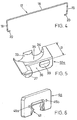
- ein teilweise montierter Wagen der Linearbewegungsführung aus Fig. 1 in einer Teilansicht;
- Fig. 3
- ein Grundkörper des Wagens von Fig. 1 in einer perspektivischen Darstellung;
- Fig. 4
- ein Sicherungsbügel des Wagens von Fig.1;
- Fig. 5
- ein Umlenkkörper in einer perspektivischen Darstellung;
- Fig. 6
- eine Deckplatte mit einem Abstreifer in einer perspektivischen Darstellung.
- Fig. 7
- ein Teil einer Längsschnittdarstellung eines erfindungsgemässen Wagens.
Claims (15)
- Wagen einer Linearbewegungsführung, welcher zur Anordnung auf einer Schiene vorgesehen ist, der einen Mittelabschnitt und zwei sich jeweils an den Mittelabschnitt anschliessende Schenkel aufweist, wodurch der Wagen im Querschnitt im wesentlichen U-förmig ausgebildet ist und eine zur vorgesehenen Längsbewegungsachse parallel verlaufende Ausnehmung aufweist, der Wagen im Bereich der beiden Schenkel zumindest jeweils einen Wälzkörperumlauf aufweist, wobei jeder Wälzkörperumlauf einen Rücklaufkanal, eine Tragzone sowie zwei den Rücklaufkanal und die Tragzone miteinander verbindende Umlenkkanäle aufweist, dadurch gekennzeichnet, dass zumindest ein Schenkel (3a, 3b) mit zumindest einer Nut (22a, 22b, 22c, 22d) versehen ist, und dass in die Nut (22a, 22b, 22c, 22d) ein Einsatz (32a, 32b) einfügbar ist, welcher Mittel zur Umlenkung der Wälzkörper (7) enthält.
- Wagen nach Anspruch 1, dadurch gekennzeichnet, dass die Nut (22a, 22b, 22c, 22d) im wesentlichen quer zur Ausnehmung verläuft.
- Wagen nach einem oder beiden der vorhergehenden Ansprüche, dadurch gekennzeichnet, dass die Nut (22a, 22b, 22c, 22d) von zwei im wesentlichen orthogonal zur Längsbewegungsachse ausgerichteten Seitenflächen des Grundkörpers begrenzt wird.
- Wagen nach einem oder mehreren der vorhergehenden Ansprüche, dadurch gekennzeichnet, dass jeder Schenkel (3a, 3b) zwei solche Nuten (22a, 22b, 22c, 22d) aufweist.
- Wagen nach einem oder mehreren der vorhergehenden Ansprüche, dadurch gekennzeichnet, dass der Einsatz (32a, 32b) sowohl eine innere als auch eine äussere Führungsfläche (33, 34) der Umlenkung aufweist.
- Wagen nach einem oder mehreren der vorhergehenden Ansprüche, dadurch gekennzeichnet, dass der zumindest eine Einsatz (32a, 32b) durch eine Schnappverbindung am Grundkörper (5) befestigbar ist.
- Wagen nach Anspruch 6, dadurch gekennzeichnet, dass die Schnappverbindung ein am Einsatz (32a, 32b) angeordnetes Zentrierauge (39) sowie eine mit dem Rücklaufkanal fluchtende Ausnehmung aufweist.
- Wagen nach Anspruch einem oder mehreren der vorhergehenden Ansprüche, dadurch gekennzeichnet, dass der Einsatz (32a, 32b) Mittel zur Zentrierung gegenüber dem Rücklaufkanal und/oder der Tragzone des Wagens (11) aufweist.
- Wagen nach einem oder mehreren der vorhergehenden Ansprüche, dadurch gekennzeichnet, dass der Einsatz (32a, 32b) mit einer Zentriernase (37) versehen ist, die gegen eine Innenseite eines Steges (27a, 27b, 27c, 27d) des Grundkörpers (5) anliegt, an der sich eine Stirnfläche (8) des Grundkörpers (5) befindet.
- Wagen nach einem oder mehreren der vorhergehenden Ansprüche, gekennzeichnet durch eine Deckplatte (4a, 4b), an welcher ein Abstreifer (41) angeordnet ist, wobei die Deckplatte (4a, 4b) an einer Stirnseite des Grundkörpers (5) befestigbar ist.
- Wagen nach Anspruch 10, dadurch gekennzeichnet, dass die Deckplatte (4a, 4b) mit einer Schnappverbindung an zumindest einem Einsatz (32a, 32b) befestigbar ist.
- Wagen nach einem oder mehreren der vorhergehenden Ansprüche, dadurch gekennzeichnet, dass die Deckplatte (4a, 4b) an einem aufgrund der mindestens einen Nut (22a, 22b, 22c, 22d) ausgebildeten Steg (27a, 27b, 27c, 27d), vorzugsweise mittels einer Schnappverbindung, angebracht ist.
- Wagen nach einem oder mehreren der vorhergehenden Ansprüche, gekennzeichnet durch einen Sicherungsbügel (17), der zur Rückhaltung der Wälzkörper (7) in der Tragzone vorgesehen ist, wobei der Sicherungsbügel (17) mit einem in der Tragzone angeordneten Rückhaltesteg (18) und zwei an den Stirnseiten des Grundkörpers eingreifenden Befestigungsstege (19) versehen ist.
- Wälzkörperumlauf einer Linearbewegungsführung, welcher zur Zirkulation von Wälzörpern einen Rücklaufkanal, eine Tragzone sowie zwei den Rücklaufkanal und die Tragzone miteinander verbindende Umlenkkanäle aufweist , dadurch gekennzeichnet, dass zumindest einer der Umlenkkanäle einen in eine Nut (22a, 22b, 22c, 22d)einzufügenden Einsatz (32a, 32b) aufweist, welcher Mittel zur Umlenkung der Wälzkörper (7) enthält.
- Wälzkörperumlauf nach Anspruch 14, gekennzeichnet durch ein oder mehrere der in den Ansprüchen 2 bis 13 angeführten Merkmale.
Applications Claiming Priority (2)
| Application Number | Priority Date | Filing Date | Title |
|---|---|---|---|
| CH175498 | 1998-08-27 | ||
| CH175498 | 1998-08-27 |
Publications (2)
| Publication Number | Publication Date |
|---|---|
| EP0982509A1 true EP0982509A1 (de) | 2000-03-01 |
| EP0982509B1 EP0982509B1 (de) | 2004-10-20 |
Family
ID=4217791
Family Applications (1)
| Application Number | Title | Priority Date | Filing Date |
|---|---|---|---|
| EP99115859A Expired - Lifetime EP0982509B1 (de) | 1998-08-27 | 1999-08-12 | Linearbewegungsführung |
Country Status (4)
| Country | Link |
|---|---|
| US (1) | US6210040B1 (de) |
| EP (1) | EP0982509B1 (de) |
| JP (1) | JP4356045B2 (de) |
| DE (1) | DE59910887D1 (de) |
Cited By (1)
| Publication number | Priority date | Publication date | Assignee | Title |
|---|---|---|---|---|
| EP1245845A1 (de) * | 2001-03-29 | 2002-10-02 | Nippon Thompson Co., Ltd. | Linearführungseinheit |
Families Citing this family (12)
| Publication number | Priority date | Publication date | Assignee | Title |
|---|---|---|---|---|
| TW429290B (en) * | 2000-05-24 | 2001-04-11 | Hiwin Tech Corp | A linear guide way |
| WO2006051707A1 (ja) * | 2004-11-15 | 2006-05-18 | Thk Co., Ltd. | 運動案内装置、テーブル装置及び運動案内装置の減衰方法 |
| US7377693B2 (en) * | 2006-02-24 | 2008-05-27 | Hiwin Technologies Corp. | Steel wire retainer for a sliding block |
| US7467894B2 (en) * | 2006-05-15 | 2008-12-23 | Hiwin Technologies Corp. | Linear motion guide apparatus having ball retaining device |
| JP2010078108A (ja) * | 2008-09-29 | 2010-04-08 | Thk Co Ltd | 運動案内装置 |
| KR101893082B1 (ko) * | 2011-06-30 | 2018-08-29 | 에스엠시 가부시키가이샤 | 리니어 액추에이터 |
| TWM434859U (en) * | 2011-11-25 | 2012-08-01 | Kuo-Le Tsao | Linear slider structure improvement |
| JP6201344B2 (ja) * | 2012-03-27 | 2017-09-27 | Thk株式会社 | 運動装置 |
| US10294993B2 (en) * | 2013-03-27 | 2019-05-21 | Nsk Ltd. | Lubricant supply device for linear guide apparatus, and linear guide apparatus |
| JP6229739B2 (ja) * | 2014-02-03 | 2017-11-15 | Smc株式会社 | リニアアクチュエータ |
| TWI587975B (zh) * | 2014-02-05 | 2017-06-21 | Smc股份有限公司 | 線性致動器 |
| CN208074007U (zh) * | 2016-06-16 | 2018-11-09 | 深圳市创客工场科技有限公司 | 连接杆及连接组件 |
Citations (8)
| Publication number | Priority date | Publication date | Assignee | Title |
|---|---|---|---|---|
| EP0124648A2 (de) * | 1983-04-12 | 1984-11-14 | Ipiranga Sa | Linearlageranordnung zur geradlinigen Führung eines Schlittens längs einer Führungsschiene |
| DE3604283A1 (de) * | 1985-02-15 | 1986-08-21 | Nippon Thompson Co Ltd | Linearrollenlager mit geschlossener rollenumlaufbahn |
| US4798479A (en) * | 1987-04-14 | 1989-01-17 | Nippon Thompson Co., Ltd. | Sheet-metal type endless rectilinear motion rolling guide unit |
| DE3931351A1 (de) * | 1989-09-20 | 1991-03-28 | Werner Dipl Ing Jacob | Kugelumlaufeinheit fuer eine linearfuehrung |
| US5492413A (en) * | 1993-07-22 | 1996-02-20 | Nsk Ltd. | Sealing device for a linear guide |
| US5544954A (en) * | 1994-09-22 | 1996-08-13 | Nsk Ltd. | Ball retainers in a linear guide apparatus |
| EP0802337A2 (de) * | 1996-04-20 | 1997-10-22 | INA Wälzlager Schaeffler KG | Linearwälzlager |
| EP0845611A1 (de) * | 1996-06-18 | 1998-06-03 | Thk Co. Ltd. | Linearführungvorrichtung mit mehreren kugelkettenreihen |
Family Cites Families (3)
| Publication number | Priority date | Publication date | Assignee | Title |
|---|---|---|---|---|
| US4502737A (en) * | 1981-11-18 | 1985-03-05 | Nippon Seiko Kabushiki Kaisha | Slide way bearing |
| JPS60151417A (ja) * | 1984-01-17 | 1985-08-09 | Nippon Thompson Co Ltd | 直線運動用ころ軸受の無限循環路 |
| US5106206A (en) * | 1991-01-30 | 1992-04-21 | Nippon Thompson Co., Ltd. | Linear motion guide unit manufactured from a resin |
-
1999
- 1999-08-12 DE DE59910887T patent/DE59910887D1/de not_active Expired - Lifetime
- 1999-08-12 EP EP99115859A patent/EP0982509B1/de not_active Expired - Lifetime
- 1999-08-25 JP JP27727799A patent/JP4356045B2/ja not_active Expired - Fee Related
- 1999-08-27 US US09/384,087 patent/US6210040B1/en not_active Expired - Lifetime
Patent Citations (8)
| Publication number | Priority date | Publication date | Assignee | Title |
|---|---|---|---|---|
| EP0124648A2 (de) * | 1983-04-12 | 1984-11-14 | Ipiranga Sa | Linearlageranordnung zur geradlinigen Führung eines Schlittens längs einer Führungsschiene |
| DE3604283A1 (de) * | 1985-02-15 | 1986-08-21 | Nippon Thompson Co Ltd | Linearrollenlager mit geschlossener rollenumlaufbahn |
| US4798479A (en) * | 1987-04-14 | 1989-01-17 | Nippon Thompson Co., Ltd. | Sheet-metal type endless rectilinear motion rolling guide unit |
| DE3931351A1 (de) * | 1989-09-20 | 1991-03-28 | Werner Dipl Ing Jacob | Kugelumlaufeinheit fuer eine linearfuehrung |
| US5492413A (en) * | 1993-07-22 | 1996-02-20 | Nsk Ltd. | Sealing device for a linear guide |
| US5544954A (en) * | 1994-09-22 | 1996-08-13 | Nsk Ltd. | Ball retainers in a linear guide apparatus |
| EP0802337A2 (de) * | 1996-04-20 | 1997-10-22 | INA Wälzlager Schaeffler KG | Linearwälzlager |
| EP0845611A1 (de) * | 1996-06-18 | 1998-06-03 | Thk Co. Ltd. | Linearführungvorrichtung mit mehreren kugelkettenreihen |
Cited By (2)
| Publication number | Priority date | Publication date | Assignee | Title |
|---|---|---|---|---|
| EP1245845A1 (de) * | 2001-03-29 | 2002-10-02 | Nippon Thompson Co., Ltd. | Linearführungseinheit |
| US6520681B2 (en) | 2001-03-29 | 2003-02-18 | Nippon Thompson Co., Ltd. | Linear motion guide unit |
Also Published As
| Publication number | Publication date |
|---|---|
| JP4356045B2 (ja) | 2009-11-04 |
| US6210040B1 (en) | 2001-04-03 |
| DE59910887D1 (de) | 2004-11-25 |
| JP2000120677A (ja) | 2000-04-25 |
| EP0982509B1 (de) | 2004-10-20 |
Similar Documents
| Publication | Publication Date | Title |
|---|---|---|
| DE3627169C2 (de) | Lineare Wälzkörperführung | |
| EP2217820B1 (de) | Käfig für ein wälzkörperlager sowie verfahren zu dessen herstellung | |
| EP0982509B1 (de) | Linearbewegungsführung | |
| DE4032820C1 (de) | ||
| DE3688289T2 (de) | Beweglicher tisch. | |
| EP1236912B1 (de) | Linearbewegungsführung mit einem zwangsgeführten Käfig für Wälzkörper | |
| EP0802337B1 (de) | Linearwälzlager | |
| DE112012003767B4 (de) | Bewegungsführungsvorrichtung | |
| DE3333795A1 (de) | Waelzkoerpergelagerte laengsfuehrung mit schlitten | |
| WO2000008344A1 (de) | Wagen einer linearführung | |
| DE9011444U1 (de) | Wälzlager für Linearbewegungen | |
| DE102016012025B3 (de) | Kniehebel-Schließeinheit einer Kunststoffverarbeitungsmaschine, insbesondere einer Spritzgießmaschine | |
| DE112019005901T5 (de) | Bewegungsführungsvorrichtung | |
| EP0601028B1 (de) | Wälzlager für linearbewegungen | |
| DE3905566C1 (de) | Gleichlaufgelenk mit axial gegeneinander verschiebbaren Gelenkteilen | |
| DE4133310A1 (de) | Waelzlager-geradefuehrungseinheit mit vier endlosen waelzlagerelement-umlaufwegen | |
| DE102005004659B4 (de) | Längsführung für Fahrzeugsitze | |
| DE9011413U1 (de) | Linearantrieb | |
| DE9301112U1 (de) | Profilkörper mit Polygonkern | |
| DE4227599C2 (de) | Längsführung mit einer Wälzkörperumlauflagerung | |
| DE3317121C2 (de) | ||
| EP0040394B1 (de) | Vorrichtung zur geradlinigen Führung eines Maschinenelementes längs eines Balkens | |
| EP1308641A1 (de) | Führungswagen für Profilschienenführungen | |
| EP3231975A1 (de) | Schiebetürführung für ein kraftfahrzeug | |
| EP1612436B1 (de) | Profilschienenführung |
Legal Events
| Date | Code | Title | Description |
|---|---|---|---|
| PUAI | Public reference made under article 153(3) epc to a published international application that has entered the european phase |
Free format text: ORIGINAL CODE: 0009012 |
|
| AK | Designated contracting states |
Kind code of ref document: A1 Designated state(s): CH DE FR GB IT LI NL |
|
| AX | Request for extension of the european patent |
Free format text: AL;LT;LV;MK;RO;SI |
|
| 17P | Request for examination filed |
Effective date: 20000525 |
|
| AKX | Designation fees paid |
Free format text: CH DE FR GB IT LI NL |
|
| RBV | Designated contracting states (corrected) |
Designated state(s): CH DE FR GB IT LI NL |
|
| 17Q | First examination report despatched |
Effective date: 20031010 |
|
| GRAP | Despatch of communication of intention to grant a patent |
Free format text: ORIGINAL CODE: EPIDOSNIGR1 |
|
| GRAS | Grant fee paid |
Free format text: ORIGINAL CODE: EPIDOSNIGR3 |
|
| GRAA | (expected) grant |
Free format text: ORIGINAL CODE: 0009210 |
|
| AK | Designated contracting states |
Kind code of ref document: B1 Designated state(s): CH DE FR GB IT LI NL |
|
| REG | Reference to a national code |
Ref country code: GB Ref legal event code: FG4D Free format text: NOT ENGLISH |
|
| REG | Reference to a national code |
Ref country code: CH Ref legal event code: EP |
|
| REF | Corresponds to: |
Ref document number: 59910887 Country of ref document: DE Date of ref document: 20041125 Kind code of ref document: P |
|
| REG | Reference to a national code |
Ref country code: CH Ref legal event code: NV Representative=s name: R. A. EGLI & CO. PATENTANWAELTE |
|
| GBT | Gb: translation of ep patent filed (gb section 77(6)(a)/1977) |
Effective date: 20050116 |
|
| PLBE | No opposition filed within time limit |
Free format text: ORIGINAL CODE: 0009261 |
|
| STAA | Information on the status of an ep patent application or granted ep patent |
Free format text: STATUS: NO OPPOSITION FILED WITHIN TIME LIMIT |
|
| ET | Fr: translation filed | ||
| 26N | No opposition filed |
Effective date: 20050721 |
|
| PGFP | Annual fee paid to national office [announced via postgrant information from national office to epo] |
Ref country code: FR Payment date: 20070812 Year of fee payment: 9 |
|
| REG | Reference to a national code |
Ref country code: FR Ref legal event code: ST Effective date: 20090430 |
|
| PG25 | Lapsed in a contracting state [announced via postgrant information from national office to epo] |
Ref country code: FR Free format text: LAPSE BECAUSE OF NON-PAYMENT OF DUE FEES Effective date: 20080901 |
|
| PGFP | Annual fee paid to national office [announced via postgrant information from national office to epo] |
Ref country code: GB Payment date: 20100819 Year of fee payment: 12 |
|
| GBPC | Gb: european patent ceased through non-payment of renewal fee |
Effective date: 20110812 |
|
| PG25 | Lapsed in a contracting state [announced via postgrant information from national office to epo] |
Ref country code: GB Free format text: LAPSE BECAUSE OF NON-PAYMENT OF DUE FEES Effective date: 20110812 |
|
| PGFP | Annual fee paid to national office [announced via postgrant information from national office to epo] |
Ref country code: DE Payment date: 20180823 Year of fee payment: 20 Ref country code: NL Payment date: 20180821 Year of fee payment: 20 Ref country code: IT Payment date: 20180830 Year of fee payment: 20 |
|
| PGFP | Annual fee paid to national office [announced via postgrant information from national office to epo] |
Ref country code: CH Payment date: 20181128 Year of fee payment: 20 |
|
| REG | Reference to a national code |
Ref country code: DE Ref legal event code: R071 Ref document number: 59910887 Country of ref document: DE |
|
| REG | Reference to a national code |
Ref country code: NL Ref legal event code: MK Effective date: 20190811 |
|
| REG | Reference to a national code |
Ref country code: CH Ref legal event code: PL |