EP0982527A1 - Distributeur de lubrifiant - Google Patents
Distributeur de lubrifiant Download PDFInfo
- Publication number
- EP0982527A1 EP0982527A1 EP98115883A EP98115883A EP0982527A1 EP 0982527 A1 EP0982527 A1 EP 0982527A1 EP 98115883 A EP98115883 A EP 98115883A EP 98115883 A EP98115883 A EP 98115883A EP 0982527 A1 EP0982527 A1 EP 0982527A1
- Authority
- EP
- European Patent Office
- Prior art keywords
- lubricant
- piston pump
- differential piston
- drive
- output
- Prior art date
- Legal status (The legal status is an assumption and is not a legal conclusion. Google has not performed a legal analysis and makes no representation as to the accuracy of the status listed.)
- Withdrawn
Links
- 239000000314 lubricant Substances 0.000 title claims abstract description 68
- 238000005461 lubrication Methods 0.000 claims description 7
- 238000012806 monitoring device Methods 0.000 claims description 6
- 230000006835 compression Effects 0.000 claims description 4
- 238000007906 compression Methods 0.000 claims description 4
- 230000000750 progressive effect Effects 0.000 claims description 4
- 238000006243 chemical reaction Methods 0.000 description 2
- 239000012530 fluid Substances 0.000 description 1
- 238000000034 method Methods 0.000 description 1
Images

Classifications
-
- F—MECHANICAL ENGINEERING; LIGHTING; HEATING; WEAPONS; BLASTING
- F16—ENGINEERING ELEMENTS AND UNITS; GENERAL MEASURES FOR PRODUCING AND MAINTAINING EFFECTIVE FUNCTIONING OF MACHINES OR INSTALLATIONS; THERMAL INSULATION IN GENERAL
- F16N—LUBRICATING
- F16N7/00—Arrangements for supplying oil or unspecified lubricant from a stationary reservoir or the equivalent in or on the machine or member to be lubricated
- F16N7/38—Arrangements for supplying oil or unspecified lubricant from a stationary reservoir or the equivalent in or on the machine or member to be lubricated with a separate pump; Central lubrication systems
- F16N7/385—Central lubrication systems
-
- F—MECHANICAL ENGINEERING; LIGHTING; HEATING; WEAPONS; BLASTING
- F16—ENGINEERING ELEMENTS AND UNITS; GENERAL MEASURES FOR PRODUCING AND MAINTAINING EFFECTIVE FUNCTIONING OF MACHINES OR INSTALLATIONS; THERMAL INSULATION IN GENERAL
- F16N—LUBRICATING
- F16N11/00—Arrangements for supplying grease from a stationary reservoir or the equivalent in or on the machine or member to be lubricated; Grease cups
- F16N11/08—Arrangements for supplying grease from a stationary reservoir or the equivalent in or on the machine or member to be lubricated; Grease cups with mechanical drive, other than directly by springs or weights
-
- F—MECHANICAL ENGINEERING; LIGHTING; HEATING; WEAPONS; BLASTING
- F16—ENGINEERING ELEMENTS AND UNITS; GENERAL MEASURES FOR PRODUCING AND MAINTAINING EFFECTIVE FUNCTIONING OF MACHINES OR INSTALLATIONS; THERMAL INSULATION IN GENERAL
- F16N—LUBRICATING
- F16N11/00—Arrangements for supplying grease from a stationary reservoir or the equivalent in or on the machine or member to be lubricated; Grease cups
- F16N11/10—Arrangements for supplying grease from a stationary reservoir or the equivalent in or on the machine or member to be lubricated; Grease cups by pressure of another fluid
-
- F—MECHANICAL ENGINEERING; LIGHTING; HEATING; WEAPONS; BLASTING
- F16—ENGINEERING ELEMENTS AND UNITS; GENERAL MEASURES FOR PRODUCING AND MAINTAINING EFFECTIVE FUNCTIONING OF MACHINES OR INSTALLATIONS; THERMAL INSULATION IN GENERAL
- F16N—LUBRICATING
- F16N13/00—Lubricating-pumps
- F16N13/02—Lubricating-pumps with reciprocating piston
Definitions
- the invention relates to a lubricator for continuous and automatic Lubricate machine parts, especially bearings, with one the machine to be lubricated connectable housing in which a Lubricant reservoir and a driven piston Dispensing device for dispensing the lubricant arranged are.
- Lubricator of the type mentioned are known in a variety of embodiments from the prior art.
- DE-A1-195 44 692 discloses a lubricant dispenser with electromotive-controlled dispensing of the lubricant.
- These lubricators are used to lubricate machines or system parts that are difficult to access or far away or that would need to be stopped to lubricate the machine to be lubricated.
- the generic lubricators are connected to the machines to be lubricated.
- a gas generator or an electric motor drive then continuously delivers metered lubricant from the lubricant reservoir to the machine.
- the lubricant reservoir of a lubricator can, for example, guarantee continuous lubrication for up to one year.
- the electromotive drive acts via a reduction gear and a thrust gear on an actuating piston arranged in the housing of the lubricant dispenser, via which the lubricant arranged below the actuating piston is pressed out of the housing.
- These known lubricators work with output pressures of about 5 bar and delivery rates of at least 100 mm 3 per piston stroke.
- the object of the invention is to improve a lubricant dispenser of the type mentioned at the outset in such a way that it has a simple structure and is suitable for generating high dispensing pressures and low dispensing quantities.
- the solution to this problem is characterized in that the output device is designed as a differential piston pump.
- a first embodiment of the invention serves as a drive for the Differential piston pump a gas produced by a gas generator, the via a valve, preferably a micro valve, of the differential piston pump is feedable.
- a valve preferably a micro valve
- this type of drive either one runs in the gas generator chemical reaction associated with strong gas evolution or it a compressed gas is used.
- To control the Differential piston pump is between the gas generator and the pump Valve switched.
- This valve can be used, for example, as a reusable valve, in particular 3/2 or 4/2 directional control valve.
- a second embodiment of the invention serves as a drive for the Differential piston pump a direct electromotive drive.
- the type of drive is the piston of the differential piston pump via a piston rod connected to the electric motor drive so that the piston directly over the piston rod can be moved up and down.
- the dispensers to other dispense quantities and / or one to be able to set another output clock is the drive of the output device connected to a control and monitoring device.
- the suction pressure that is necessary to get the lubricant out of the lubricant reservoir via a suction line connected to the differential piston pump can be reduced by the fact that the lubricant reservoir is pressurized via a compression spring and thus in the Lubricant reservoir is under pressure.
- the differential piston pump is the lubricant to the system parts to be lubricated via an output line with a lubricant distributor, in particular connected to a progressive distributor.
- a lubricant distributor in particular connected to a progressive distributor.
- the invention proposes that in the output line Check valves are arranged to the lubricant distributor. This Check valve is used to ensure that the suction Differential piston pump no lubricant from the discharge line and the Lubricant distributor is sucked in.
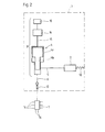
- the lubricators shown in Figures 1 and 2 consist of essentially from a housing 1 shown in dashed lines arranged lubricant reservoir 2 and an output device 3 for Output of the lubricant stored in the lubricant reservoir to a machine not shown.
- An essential part of the output device 3 is a Differential piston pump 4 with an axially in a cylinder housing 4a movable graduated piston 4b.
- Lubricant via the differential piston pump 4 is the differential piston pump 4 on the one hand via a suction line 5 to the lubricant reservoir 2 and on the other hand via an output line 6 to a lubricant distributor 7 connected. If there is only one lubrication point, the output line 6 can also be connected directly to the machine, the parts of which must be lubricated.
- a lubricator shown in FIG. 1 serves as a drive for the differential piston pump 4 in a gas generator 8 gas produced.
- the gas generation takes place here in the Gas generator 8 chemical reaction or the release of a compressed gas.
- the gas generated in the gas generator 8 is a Valve 9, in the illustrated embodiment, a 4/2-way valve, which as Microvalve is formed, the differential piston pump 4 supplied.
- the Control of the gas generator 8 and the valve 9 takes place via a Control and monitoring device 10.
- the lubricator shown in Fig. 1 works as follows:
- valve 9 After completion of the suction process, the valve 9 is switched over and that Gas from the gas generator 8 via an upper pressure medium line 11b of the differential piston pump 4 forwarded.
- the piston 4b By acting on the upper piston surface of the stepped piston 4b while opening the lower one Pressure fluid line 11a back to the valve 9, the piston 4b through the Gas pressure moved down and the suctioned in the previous suction phase Lubricant via the output line 6 to the lubricant distributor 7 pressed out of the cylinder housing 4a of the differential piston pump 4.
- Output lines 6 check valves 13 arranged.
- the check valve 13 in the output line 6 is arranged so that it is in the suction phase Differential piston pump 4 prevents lubricant from the Output line 6 or the lubricant distributor 7 is sucked off.
- the pressure phase gives the check valve 13 in the output line 6 clear the way for the lubricant towards the lubricant distributor 7.
- control and monitoring device 10 is used to change the output device 3 to different lubricant programs to be able to, that is the output quantity and / or the output clock of To vary lubricant.
- Fig. 2 serves as a drive for the differential piston pump 4 an electromotive drive 14.
- This electromotive Drive 14 is via a piston rod 15 directly with the stepped Piston 4b of the differential piston pump 4 connected.
- the way of working the differential piston pump 4 in the suction phase and the pressure phase corresponds to that previously described for the first embodiment Way of working.
- the differential piston pump 4 By using the differential piston pump 4 with the graduated Piston 4b with the different piston areas, it is possible to have a high Generate output pressure with which the lubricant passes through the output line 6 is fed to the lubricant distributor 7. These pressures can be over 10 bar. Due to these high output pressures, it is possible to design the lubricant distributor 7, for example, as a progressive distributor, so that several to a lubricant distributor 7 of a lubricator Machines can be connected via machine connecting lines 16. in the illustrated case, it is possible to connect up to eight machines to one Lubricant distributor 7 to connect only one lubricator. Of course, it is also possible to have more than eight machines at the same time or one after the other via a lubricant distributor 7 with lubricant supply.
- the two illustrated exemplary embodiments of a lubricant dispenser are characterized in that, by using the differential piston pump 4 as the heart of the dispensing device 3, it is possible on the one hand to output small amounts of lubricant of less than 100 mm 3 per stroke and on the other hand high pressures of> 5 bar and in particular> Generate 10 bar. Because of the larger areas of application of these lubricators compared to the prior art, which can also be used for the simultaneous lubrication of several machines, these lubricators have a considerable cost advantage over the lubricators of the prior art.
Landscapes
- Engineering & Computer Science (AREA)
- General Engineering & Computer Science (AREA)
- Mechanical Engineering (AREA)
- Reciprocating Pumps (AREA)
- Details Of Reciprocating Pumps (AREA)
Priority Applications (2)
| Application Number | Priority Date | Filing Date | Title |
|---|---|---|---|
| EP98115883A EP0982527A1 (fr) | 1998-08-22 | 1998-08-22 | Distributeur de lubrifiant |
| CA002299490A CA2299490A1 (fr) | 1998-08-22 | 2000-02-24 | Distributeur de lubrifiant |
Applications Claiming Priority (2)
| Application Number | Priority Date | Filing Date | Title |
|---|---|---|---|
| EP98115883A EP0982527A1 (fr) | 1998-08-22 | 1998-08-22 | Distributeur de lubrifiant |
| CA002299490A CA2299490A1 (fr) | 1998-08-22 | 2000-02-24 | Distributeur de lubrifiant |
Publications (1)
| Publication Number | Publication Date |
|---|---|
| EP0982527A1 true EP0982527A1 (fr) | 2000-03-01 |
Family
ID=25681567
Family Applications (1)
| Application Number | Title | Priority Date | Filing Date |
|---|---|---|---|
| EP98115883A Withdrawn EP0982527A1 (fr) | 1998-08-22 | 1998-08-22 | Distributeur de lubrifiant |
Country Status (2)
| Country | Link |
|---|---|
| EP (1) | EP0982527A1 (fr) |
| CA (1) | CA2299490A1 (fr) |
Cited By (8)
| Publication number | Priority date | Publication date | Assignee | Title |
|---|---|---|---|---|
| WO2005003619A3 (fr) * | 2003-07-07 | 2005-05-06 | A T S Electro Lube Holdings Lt | Distribution de liquide reutilisable |
| US8783418B2 (en) | 2004-05-06 | 2014-07-22 | Natasa Enterprises Ltd | Automatic motor driven in-line piston pump lubricator |
| EP2803896A1 (fr) * | 2013-05-15 | 2014-11-19 | Korihuolto Moksi Oy | Graisseur |
| US9151443B2 (en) | 2009-02-22 | 2015-10-06 | Stephania Holdings Inc. | Fluid holder and electromechanical lubricator employing same |
| CN105351713A (zh) * | 2015-12-09 | 2016-02-24 | 重庆蜂糖妹农业开发有限公司 | 运输线的自动润滑装置 |
| CN109340546A (zh) * | 2018-11-15 | 2019-02-15 | 安徽工程大学 | 一种高黏稠润滑脂供脂泵送系统及方法 |
| CN119755505A (zh) * | 2025-03-05 | 2025-04-04 | 江苏嘉通能源有限公司 | 润滑剂安全加注装置及其控制系统、控制方法 |
| CN120521134A (zh) * | 2025-07-23 | 2025-08-22 | 成都中寰流体控制设备股份有限公司 | 一种防爆电动注入泵 |
Families Citing this family (2)
| Publication number | Priority date | Publication date | Assignee | Title |
|---|---|---|---|---|
| EP3809034B1 (fr) | 2019-10-17 | 2024-02-07 | Ratier-Figeac SAS | Systeme de lubrification |
| CA3193551A1 (fr) | 2020-09-24 | 2022-03-31 | John Peter SMID | Appareil de distribution de lubrifiant |
Citations (5)
| Publication number | Priority date | Publication date | Assignee | Title |
|---|---|---|---|---|
| FR2188785A5 (fr) * | 1972-06-08 | 1974-01-18 | Mccord Corp | |
| EP0244182A2 (fr) * | 1986-05-01 | 1987-11-04 | Castrol Limited | Dispositifs de graissage |
| US5285871A (en) * | 1992-08-17 | 1994-02-15 | Mechanical Tool & Engineering Co. | System for distributing viscous lubricant |
| DE19544692A1 (de) | 1994-06-29 | 1997-06-05 | Satzinger Gmbh & Co | Schmierstoffspender mit elektromotorisch gesteuerter Abgabe eines Schmierstoffes an eine Maschine |
| US5667037A (en) * | 1995-11-06 | 1997-09-16 | Orlitzky; Anton | Lubrication system |
-
1998
- 1998-08-22 EP EP98115883A patent/EP0982527A1/fr not_active Withdrawn
-
2000
- 2000-02-24 CA CA002299490A patent/CA2299490A1/fr not_active Abandoned
Patent Citations (5)
| Publication number | Priority date | Publication date | Assignee | Title |
|---|---|---|---|---|
| FR2188785A5 (fr) * | 1972-06-08 | 1974-01-18 | Mccord Corp | |
| EP0244182A2 (fr) * | 1986-05-01 | 1987-11-04 | Castrol Limited | Dispositifs de graissage |
| US5285871A (en) * | 1992-08-17 | 1994-02-15 | Mechanical Tool & Engineering Co. | System for distributing viscous lubricant |
| DE19544692A1 (de) | 1994-06-29 | 1997-06-05 | Satzinger Gmbh & Co | Schmierstoffspender mit elektromotorisch gesteuerter Abgabe eines Schmierstoffes an eine Maschine |
| US5667037A (en) * | 1995-11-06 | 1997-09-16 | Orlitzky; Anton | Lubrication system |
Cited By (9)
| Publication number | Priority date | Publication date | Assignee | Title |
|---|---|---|---|---|
| WO2005003619A3 (fr) * | 2003-07-07 | 2005-05-06 | A T S Electro Lube Holdings Lt | Distribution de liquide reutilisable |
| US8783418B2 (en) | 2004-05-06 | 2014-07-22 | Natasa Enterprises Ltd | Automatic motor driven in-line piston pump lubricator |
| US9151443B2 (en) | 2009-02-22 | 2015-10-06 | Stephania Holdings Inc. | Fluid holder and electromechanical lubricator employing same |
| EP2803896A1 (fr) * | 2013-05-15 | 2014-11-19 | Korihuolto Moksi Oy | Graisseur |
| CN105351713A (zh) * | 2015-12-09 | 2016-02-24 | 重庆蜂糖妹农业开发有限公司 | 运输线的自动润滑装置 |
| CN109340546A (zh) * | 2018-11-15 | 2019-02-15 | 安徽工程大学 | 一种高黏稠润滑脂供脂泵送系统及方法 |
| CN109340546B (zh) * | 2018-11-15 | 2020-11-20 | 安徽工程大学 | 一种高黏稠润滑脂供脂泵送系统及方法 |
| CN119755505A (zh) * | 2025-03-05 | 2025-04-04 | 江苏嘉通能源有限公司 | 润滑剂安全加注装置及其控制系统、控制方法 |
| CN120521134A (zh) * | 2025-07-23 | 2025-08-22 | 成都中寰流体控制设备股份有限公司 | 一种防爆电动注入泵 |
Also Published As
| Publication number | Publication date |
|---|---|
| CA2299490A1 (fr) | 2001-08-24 |
Similar Documents
| Publication | Publication Date | Title |
|---|---|---|
| EP1760312A2 (fr) | Pompe haute pression | |
| EP2024140A1 (fr) | Pompe à lubrifiant automatique avec piston d'entraînement à double action | |
| EP0982527A1 (fr) | Distributeur de lubrifiant | |
| DE10249524B4 (de) | Fluid-Versorgungseinheit, insbesondere hydraulische Versorgungseinheit | |
| EP1327100B1 (fr) | Dispositif de lubrification automatique | |
| DE4210504A1 (de) | Antrieb zur Hubverlagerung für Umformmaschinen | |
| EP4377571A1 (fr) | Pompe à piston haute pression et utilisation d'une pompe à piston haute pression | |
| WO2009033569A1 (fr) | Système de lubrification à la graisse, agencement de paliers pourvu de ce système de lubrification à la graisse et procédé de lubrification de cet agencement de paliers au moyen de ce système de lubrification à la graisse | |
| EP4426953B1 (fr) | Procédé de surveillance d'un système hydraulique | |
| EP2554892A1 (fr) | Convertisseur de moyen de pression | |
| DE102014223479B3 (de) | Verfahren zur Einstellung einer Anschlagposition eines hydrostatischen Kupplungsaktors | |
| EP0545243A2 (fr) | Circuit hydraulique pour véhicule automobile | |
| EP0786047A1 (fr) | Dispositif d'injection de carburant et d'alimentation en lubrifiant pour moteurs a combustion interne | |
| DE102007062030A1 (de) | Hydraulikfluidpumpe einer Fahrzeugbremsanlage mit einem Fördermittel | |
| EP0375888B1 (fr) | Presse à vis | |
| DE10119688B4 (de) | Schmierstoffspender | |
| DE1600352B2 (de) | Schmiersystem für eine Kraftmaschine | |
| DE3048521A1 (de) | Hydraulische presse | |
| DE19506320C1 (de) | Kalander | |
| EP1843040B1 (fr) | Procédé d'utilisation d'une pompe volumétrique oscillantes et pompes volumétriques oscillantes | |
| WO2007003253A1 (fr) | Unite compresseur dote d'un engrenage excentrique | |
| WO2000022300A1 (fr) | Dispositif de traitement thermique et de commande d'un milieu gazeux | |
| DE102019130210B4 (de) | Kolbenverdichter mit Energiespareinrichtung | |
| DE20118920U1 (de) | Selbsttätige Schmiereinrichtung | |
| DE906294C (de) | Vorrichtung zur Umwandlung der Energie einer mit hin und her gehendem Kolben ausgeruesteten Brennkraftmaschine in Stroemungs- arbeit eines stroemungsfaehigen Mediums |
Legal Events
| Date | Code | Title | Description |
|---|---|---|---|
| PUAI | Public reference made under article 153(3) epc to a published international application that has entered the european phase |
Free format text: ORIGINAL CODE: 0009012 |
|
| 17P | Request for examination filed |
Effective date: 19990324 |
|
| AK | Designated contracting states |
Kind code of ref document: A1 Designated state(s): AT BE CH DE DK ES FR GB IT LI LU NL SE |
|
| AX | Request for extension of the european patent |
Free format text: AL;LT;LV;MK;RO;SI |
|
| AKX | Designation fees paid |
Free format text: AT BE CH DE DK ES FR GB IT LI LU NL SE |
|
| AXX | Extension fees paid |
Free format text: SI PAYMENT 20000127 |
|
| STAA | Information on the status of an ep patent application or granted ep patent |
Free format text: STATUS: THE APPLICATION HAS BEEN WITHDRAWN |
|
| 18W | Application withdrawn |
Withdrawal date: 20010206 |