EP2554892A1 - Convertisseur de moyen de pression - Google Patents
Convertisseur de moyen de pression Download PDFInfo
- Publication number
- EP2554892A1 EP2554892A1 EP11006369A EP11006369A EP2554892A1 EP 2554892 A1 EP2554892 A1 EP 2554892A1 EP 11006369 A EP11006369 A EP 11006369A EP 11006369 A EP11006369 A EP 11006369A EP 2554892 A1 EP2554892 A1 EP 2554892A1
- Authority
- EP
- European Patent Office
- Prior art keywords
- lubricant
- piston
- pressure
- pump
- oil
- Prior art date
- Legal status (The legal status is an assumption and is not a legal conclusion. Google has not performed a legal analysis and makes no representation as to the accuracy of the status listed.)
- Withdrawn
Links
- 239000000314 lubricant Substances 0.000 claims abstract description 45
- 238000013022 venting Methods 0.000 claims description 2
- 230000003247 decreasing effect Effects 0.000 claims 1
- 239000004519 grease Substances 0.000 description 6
- 238000005461 lubrication Methods 0.000 description 6
- 230000007423 decrease Effects 0.000 description 2
- 238000012423 maintenance Methods 0.000 description 2
- 229910000831 Steel Inorganic materials 0.000 description 1
- 238000010276 construction Methods 0.000 description 1
- 230000001419 dependent effect Effects 0.000 description 1
- 238000007599 discharging Methods 0.000 description 1
- 210000003746 feather Anatomy 0.000 description 1
- 238000010438 heat treatment Methods 0.000 description 1
- 238000009434 installation Methods 0.000 description 1
- 230000001050 lubricating effect Effects 0.000 description 1
- 238000013021 overheating Methods 0.000 description 1
- 238000005086 pumping Methods 0.000 description 1
- 238000004064 recycling Methods 0.000 description 1
- 239000010959 steel Substances 0.000 description 1
Images
Classifications
-
- F—MECHANICAL ENGINEERING; LIGHTING; HEATING; WEAPONS; BLASTING
- F16—ENGINEERING ELEMENTS AND UNITS; GENERAL MEASURES FOR PRODUCING AND MAINTAINING EFFECTIVE FUNCTIONING OF MACHINES OR INSTALLATIONS; THERMAL INSULATION IN GENERAL
- F16N—LUBRICATING
- F16N7/00—Arrangements for supplying oil or unspecified lubricant from a stationary reservoir or the equivalent in or on the machine or member to be lubricated
- F16N7/38—Arrangements for supplying oil or unspecified lubricant from a stationary reservoir or the equivalent in or on the machine or member to be lubricated with a separate pump; Central lubrication systems
Definitions
- the present invention relates to a device for returning used lubricants from consumers to a collection point, wherein a consumer is associated with a pump element for receiving and forwarding excess lubricant, which has a against the action of a return spring driven piston.
- a generic device is from the EP 0 715 118 known. This discloses the consumer in the return line downstream of a pump element, which sucks excess lubricant from the consumer when pressed and then pushes out in the direction of the collection point. It is assumed that the pump element has an axially movable piston which is driven directly against the force of a return spring from the lubricant itself.
- the present invention has the object to improve a device for recycling of used lubricants of the generic type such that it has a longer service life, is less susceptible to external influences and ensures a safer operation.
- a self-contained drive circuit is designed to drive the pump elements, which uses a less viscous oil as the drive medium compared to the lubricant.
- the circuit is closed in itself and is controlled by a piston, which in turn is acted upon in a pressure medium converter according to the invention with the pressure of the lubricant in the main supply line.
- the drive circuit of the pump elements is decoupled from the actual lubricant circuit.
- the oil used eliminates the vulnerabilities of the pump elements, the valves, lines and pistons due to long service life, low temperatures and the like verharzenden or hardening lubricants.
- it can also be responded to overheating and the like by appropriate safety valves. So can any air pressure, z. B. by heating in the warehouse, are blown off when the safety valve is arranged in the grease suction side.
- the installation and connection options of such systems are significantly improved by the decoupling, because even larger distances can be overcome with the Steuerdietarymaschinen drive oil circuit.
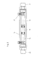
- the pressure medium converter according to the invention is cylindrical in accordance with a proposal of the invention.
- the lubricant line is connected, so that here the respective lubricant pressure is applied.
- the oil circuit is connected to drive the pump elements.
- an axially movable piston is arranged, which thus transmits the lubricant pressure to the drive oil pressure.
- the drive pressure it is also possible to adapt the drive pressure to the components. It is also possible within the scope of the invention to influence the drive pressure independently of the pressure medium converter.
- an additional control piston which can be controlled in any way, could be used to suck and / or forward excess lubricant between the lubrication phases.
- the pump element and / or the pressure medium converter consists of a steel housing with seawater-protected surface.
- the system elements are also suitable for use, for example, offshore wind turbines. Due to the decoupling of both systems, the disposal pressure can be set independently of the working pressure of the lubrication system. At working pressures of 150 or 200 bar, for example, disposal pressures between 100 and 200 bar can be set.
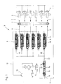
- An inventive device 1 is according to Fig. 1 shown in the area of a shaft bearing 2 exemplified. Over a plurality of output elements 3 lubricant is applied to different desired bearings of the shaft bearing 2. The lubricant also comes from a source of lubricant 4, which via a Valve 5 is guided to a lubricant line 6 to the dispensing points 3. For this purpose, a corresponding pressure is built up.
- the lubricant is then applied to different lubricant sites 7.
- oil pressure is conducted from a cylinder chamber 16 via a line 17 into a corresponding working line 18 to the pump 9.
- This oil pressure in turn is controlled in a pressure medium converter by the reciprocation of a piston 19, which in turn is acted upon on the side facing away from the oil volume with the system pressure of the lubricant via the line 15.
- the pressure medium converter 14 is in Fig. 2 shown in detail. It has the chamber 15 for the under system pressure guided grease, to which a connection 20 is provided to the system line. It has the chamber for the oil to drive the pump, to which a port 21 leads into an oil pressure line. Screws 22 are arranged for venting, filling or sucking on the respective connection areas.
- the system functions so that upon application of a lubricant pressure in the conduit 6 via the branch 15 and the chamber 15 of the pressure medium converter, the piston 19 is moved. There is pressure in the oil chamber 16 and thus in the lines 17 and 18 to the pump 9. Thus, the piston 11 moves in the pump so that in the Pump chamber collected excess fat in the manifold 12 and the reservoir 13 is performed. At the same time, lubricant is guided via the applicators 3 to the lubrication points 7. If the lubrication pressure decreases, the oil pressure in the chamber 16 also decreases. The spring-loaded piston 11 of each pump element 9 moves back in the other direction. In this way, excess lubricant is sucked through the lines 8 in the pump chamber.
- the oil flows via the lines 18 and 17 back into the chamber 16 and pushes the piston 19 against the dropped lubricant pressure in the chamber 15 back.
Landscapes
- Engineering & Computer Science (AREA)
- General Engineering & Computer Science (AREA)
- Mechanical Engineering (AREA)
- Details Of Reciprocating Pumps (AREA)
Priority Applications (1)
| Application Number | Priority Date | Filing Date | Title |
|---|---|---|---|
| EP11006369A EP2554892A1 (fr) | 2011-08-03 | 2011-08-03 | Convertisseur de moyen de pression |
Applications Claiming Priority (1)
| Application Number | Priority Date | Filing Date | Title |
|---|---|---|---|
| EP11006369A EP2554892A1 (fr) | 2011-08-03 | 2011-08-03 | Convertisseur de moyen de pression |
Publications (1)
| Publication Number | Publication Date |
|---|---|
| EP2554892A1 true EP2554892A1 (fr) | 2013-02-06 |
Family
ID=44680973
Family Applications (1)
| Application Number | Title | Priority Date | Filing Date |
|---|---|---|---|
| EP11006369A Withdrawn EP2554892A1 (fr) | 2011-08-03 | 2011-08-03 | Convertisseur de moyen de pression |
Country Status (1)
| Country | Link |
|---|---|
| EP (1) | EP2554892A1 (fr) |
Cited By (6)
| Publication number | Priority date | Publication date | Assignee | Title |
|---|---|---|---|---|
| CN105972418A (zh) * | 2016-06-02 | 2016-09-28 | 湘电风能有限公司 | 一种轴承自动润滑与废脂收集系统 |
| CN106653226A (zh) * | 2017-01-12 | 2017-05-10 | 芜湖航天特种电缆厂股份有限公司 | 方便润滑的束线装置 |
| CN106782914A (zh) * | 2017-01-12 | 2017-05-31 | 芜湖航天特种电缆厂股份有限公司 | 束线装置 |
| CN108799807A (zh) * | 2018-09-12 | 2018-11-13 | 湘电风能有限公司 | 一种轴承自动润滑与废脂收集系统 |
| CN113915506A (zh) * | 2020-07-10 | 2022-01-11 | 郑州奥特科技有限公司 | 一种双线润滑换脂系统及其流体介质注入方法 |
| CN114017655A (zh) * | 2021-11-04 | 2022-02-08 | 丰顺县泰雅达实业有限公司 | 一种自动注油装置 |
Citations (3)
| Publication number | Priority date | Publication date | Assignee | Title |
|---|---|---|---|---|
| EP0590215A1 (fr) * | 1992-09-22 | 1994-04-06 | De Limon Fluhme Gmbh | Dispositif d'alimentation de lubrifiant |
| EP0715118A1 (fr) | 1994-11-28 | 1996-06-05 | Lincoln GmbH | Système de recirculation pour des lubrifiants utilisés |
| DE19900560A1 (de) * | 1999-01-09 | 2000-07-13 | Sms Demag Ag | Schmierölumlaufsystem |
-
2011
- 2011-08-03 EP EP11006369A patent/EP2554892A1/fr not_active Withdrawn
Patent Citations (3)
| Publication number | Priority date | Publication date | Assignee | Title |
|---|---|---|---|---|
| EP0590215A1 (fr) * | 1992-09-22 | 1994-04-06 | De Limon Fluhme Gmbh | Dispositif d'alimentation de lubrifiant |
| EP0715118A1 (fr) | 1994-11-28 | 1996-06-05 | Lincoln GmbH | Système de recirculation pour des lubrifiants utilisés |
| DE19900560A1 (de) * | 1999-01-09 | 2000-07-13 | Sms Demag Ag | Schmierölumlaufsystem |
Cited By (8)
| Publication number | Priority date | Publication date | Assignee | Title |
|---|---|---|---|---|
| CN105972418A (zh) * | 2016-06-02 | 2016-09-28 | 湘电风能有限公司 | 一种轴承自动润滑与废脂收集系统 |
| CN106653226A (zh) * | 2017-01-12 | 2017-05-10 | 芜湖航天特种电缆厂股份有限公司 | 方便润滑的束线装置 |
| CN106782914A (zh) * | 2017-01-12 | 2017-05-31 | 芜湖航天特种电缆厂股份有限公司 | 束线装置 |
| CN106653226B (zh) * | 2017-01-12 | 2018-11-06 | 芜湖航天特种电缆厂股份有限公司 | 方便润滑的束线装置 |
| CN108799807A (zh) * | 2018-09-12 | 2018-11-13 | 湘电风能有限公司 | 一种轴承自动润滑与废脂收集系统 |
| CN113915506A (zh) * | 2020-07-10 | 2022-01-11 | 郑州奥特科技有限公司 | 一种双线润滑换脂系统及其流体介质注入方法 |
| CN114017655A (zh) * | 2021-11-04 | 2022-02-08 | 丰顺县泰雅达实业有限公司 | 一种自动注油装置 |
| CN114017655B (zh) * | 2021-11-04 | 2023-01-10 | 丰顺县泰雅达实业有限公司 | 一种自动注油装置 |
Similar Documents
| Publication | Publication Date | Title |
|---|---|---|
| EP1592887B1 (fr) | Pompe haute pression | |
| EP2554892A1 (fr) | Convertisseur de moyen de pression | |
| EP2345834B1 (fr) | Dispositif de lubrification et procédé de fonctionnement du dispositif de lubrification | |
| EP2128443B1 (fr) | Elément de pompe | |
| EP2491273B1 (fr) | Moteur de broche | |
| EP0702755A1 (fr) | Regulateur a plusieurs etages pour pompes a lubrifiant a debit continuellement variable | |
| DE202007005273U1 (de) | Lageranordnung sowie Zumessventil und Absaugeinrichtung hierfür | |
| EP1953390A1 (fr) | Dispositif et procédé d'égalisation de poussée axiale | |
| DE202018006530U1 (de) | Fettgeschmiertes Lagersystem | |
| EP2004997A1 (fr) | Pompe de circulation et dispositif d'étanchéité qui l'accompagne | |
| DE102012001369B4 (de) | Verstellbare Hydropumpe | |
| DE4442188C1 (de) | Einrichtung zur Rückführung von verbrauchten Schmierstoffen sowie Pumpenelement hierfür | |
| EP3307447B1 (fr) | Dispositif de transmission d'un couple d'un dispositif d'entraînement vers le rouleau d'une cage de laminoir | |
| WO2016193043A1 (fr) | Pompe à palettes et procédé permettant de faire fonctionner ladite pompe | |
| DE102007022022A1 (de) | Hydrostatische Maschine und diese verwendender Wandler | |
| DE102008009943B4 (de) | Spritzgießmaschine mit einem Spindelantrieb | |
| DE102011088228B3 (de) | Schmiermittelsystem und Windkraftanlage | |
| DE102014210909B4 (de) | Schmiermittelpumpe | |
| EP3180534B1 (fr) | Actionneur d'embrayage hydrostatique doté d'un trop-plein | |
| DE3900057A1 (de) | Hydraulische steuereinheit | |
| DE102015219725A1 (de) | Verfahren zum Betreiben einer Schmiermittelpumpe in einem Getriebe für ein Fahrzeug | |
| EP1843040B1 (fr) | Procédé d'utilisation d'une pompe volumétrique oscillantes et pompes volumétriques oscillantes | |
| EP3701091A1 (fr) | Engin spécial de génie civil, notamment fraiseuse à rideau souterrain | |
| EP3084212B1 (fr) | Dispositif de refoulement pour un fluide | |
| EP2292480B1 (fr) | Système de retardateur pour un véhicule automobile |
Legal Events
| Date | Code | Title | Description |
|---|---|---|---|
| PUAI | Public reference made under article 153(3) epc to a published international application that has entered the european phase |
Free format text: ORIGINAL CODE: 0009012 |
|
| AK | Designated contracting states |
Kind code of ref document: A1 Designated state(s): AL AT BE BG CH CY CZ DE DK EE ES FI FR GB GR HR HU IE IS IT LI LT LU LV MC MK MT NL NO PL PT RO RS SE SI SK SM TR |
|
| AX | Request for extension of the european patent |
Extension state: BA ME |
|
| STAA | Information on the status of an ep patent application or granted ep patent |
Free format text: STATUS: THE APPLICATION HAS BEEN WITHDRAWN |
|
| 18W | Application withdrawn |
Effective date: 20130726 |