EP0982571A2 - Dispositif de détection du poids d'une machine agricole - Google Patents
Dispositif de détection du poids d'une machine agricole Download PDFInfo
- Publication number
- EP0982571A2 EP0982571A2 EP99113828A EP99113828A EP0982571A2 EP 0982571 A2 EP0982571 A2 EP 0982571A2 EP 99113828 A EP99113828 A EP 99113828A EP 99113828 A EP99113828 A EP 99113828A EP 0982571 A2 EP0982571 A2 EP 0982571A2
- Authority
- EP
- European Patent Office
- Prior art keywords
- lower link
- link pin
- frame
- intermediate frame
- pin
- Prior art date
- Legal status (The legal status is an assumption and is not a legal conclusion. Google has not performed a legal analysis and makes no representation as to the accuracy of the status listed.)
- Granted
Links
Images


Classifications
-
- G—PHYSICS
- G01—MEASURING; TESTING
- G01G—WEIGHING
- G01G19/00—Weighing apparatus or methods adapted for special purposes not provided for in the preceding groups
- G01G19/08—Weighing apparatus or methods adapted for special purposes not provided for in the preceding groups for incorporation in vehicles
- G01G19/12—Weighing apparatus or methods adapted for special purposes not provided for in the preceding groups for incorporation in vehicles having electrical weight-sensitive devices
-
- A—HUMAN NECESSITIES
- A01—AGRICULTURE; FORESTRY; ANIMAL HUSBANDRY; HUNTING; TRAPPING; FISHING
- A01C—PLANTING; SOWING; FERTILISING
- A01C17/00—Fertilisers or seeders with centrifugal wheels
- A01C17/006—Regulating or dosing devices
- A01C17/008—Devices controlling the quantity or the distribution pattern
Definitions
- the invention relates to a device for detecting the Weight of one of the three-point linkage of a tractor recorded attachment with a device frame and an intermediate frame on which the upper link pin and the lower link pins gripped by the catch hooks of the lower links are attached and between which force transducers are arranged for weight detection.
- Devices of the aforementioned type are used in particular for fertilizer spreaders to record the start of the spreading work amount of fertilizer absorbed and during the Scattering work spread amount by spreading with the scattered distance and the spread to record the actual spread rate per area and this with the desired or preset Compare spread rate.
- the delivery devices e.g. Dosing openings the fertilizer hopper.
- This weight acquisition when grown has the advantage that it is effective Spread rate applied regardless of the current Properties of the applied fertilizer, e.g. whose Flow behavior, can be determined and this weight detection can also take place during operation.
- a number of different systems are known which enable such weight detection. So immediately a weighing system in the tractor's three-point linkage be integrated (DE 38 20 757, 43 28 143, 43 28 144). In another known embodiment is a Weighing system integrated in the attachment by on a a weighing frame supported on the three-point intermediate frame (DE 35 39 825, DE 195 41 577, EP 0 823 197).
- the first-mentioned system that integrates on the tractor side has the advantage of universal applicability for Attachments of any kind. However, this system is So far only realized on modern large tractors existing tractors cannot be retrofitted. Must weigh leave the working position and the entire stroke be driven through.
- the second system with the attachment Integrated weighing frame leads to an increase in weight on the attachment and to an unfavorable relocation the center of gravity to the rear. So much for the weighing frame is below the grit container, the migrates Focus also upwards. This makes driving safety and off-road mobility of the tractor or the payload must be reduced.
- the invention is based, with minimal Weight increase and largely unchanged Center of gravity of the attachment an inexpensive device to propose for weight recording.
- This object is achieved in that the device frame over one attached to it and only force transducer absorbing vertical forces immediately is supported on the lower link pin, and that the Device frame and the intermediate frame over a horizontal aligned tension rod are connected.
- the force transducers are located directly on the device frame.
- the device frame is supported by the force transducers and thus the entire attachment with its payload on the lower link pin.
- the arrangement is taken so that the force transducers only vertical Absorb forces.
- the lower link pins are part of the Intermediate frame, which also only by one horizontally aligned tie rod with the device frame is connected so that only the Vertical component of the one picked up by the top link Tensile force is initiated.
- the grips horizontally aligned tie rod below the top link pin on Intermediate frame.
- the absorption of only the vertical forces on the force transducers can be realized in different ways.
- the lower link pins in the force transducers sit and this only the vertical shear forces take up.
- the force transducers can be turned on the lower link pin rest on the lower link pin preferably spherical bushings are arranged, on which the force transducers rest point-like, with which the guarantee is given that only vertical forces from the Force transducers are registered.
- the lower link pins are preferably rigid Traverse connected, which is part of the intermediate frame and the bending and torsional moments on the lower link pins records. This ensures that this Moments cannot be entered in the force transducers.
- the crossmember can be yoke-like to between to create clearance for the lower link pins, on the other hand to obtain a rigid construction.
- the force transducers are clamped between tabs on the device frame and are supported with their ends projecting beyond the tabs the lower link pin.
- the lower link pins continue to be load cells via a handlebar each, which the horizontal and lateral forces records, connected to the device frame. Thereby can be a punctiform in a particularly simple manner
- the force transducers rest on the bushings on the lower links and therefore only a transmission of vertical forces to realize the force transducers.
- spherical bearing body for the Rest arranged on the catch hooks of the lower links are provided.
- These bearing bodies are preferably rolling or Guide bearing mounted on the lower link pin. It must precautions should always be taken to ensure that the lower links do not Get in touch with the device frame.
- a particularly simple and inexpensive version of the Intermediate frame results according to one embodiment in that the yoke-like traverse from an upright standing sheet metal part is formed and with two vertically attached sheet metal supports, each of one Lower link pin brought together to form the upper link pin are the intermediate frame.
- the intermediate frame is therefore made of simple, thick-walled Sheet metal parts formed by today's laser burning technology optimal in shape and material to the Load ratios can be coordinated. Through the Arrangement of the sheet metal supports perpendicular to the yoke-like Sheet metal part results in a torsion-resistant with simple components Intermediate frame.
- the tension rod is on the device frame horizontally adjustable and by means of a Plug pin releasably attached to the intermediate frame.
- the Tension rod is adjusted in the factory assembly to compensate for any manufacturing tolerances.
- the horizontal Alignment is of particular importance in order even if the focus is shifted during operation, e.g. by reducing the amount of fertilizer in the hopper or by moving the fertilizer in the hopper inclined terrain, not to influence the weighing result.
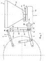
- the linkage 2 is articulated on the tractor, which receives the attachment 3 in the form of a fertilizer spreader.
- the power lift consists of two lower links 4 and a length-adjustable top link 5, both on Tractor are stored.
- the lifting cylinder engages on the lower link 4 6 on.
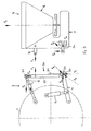
- the attachment 3 has a device frame 7, which at the embodiment shown a fertilizer container 8 picks up, as shown in Fig. 2, of two funnel-shaped Container parts 9 and 10 there. Every container part 9, 10 has on its bottom 11, 12 a not shown, controllable or adjustable dosing opening on, over the fertilizer on the rotating ones arranged underneath Spreading discs 13, 14 with spreading blades 15, 16 are applied becomes.
- the throwing discs 13, 14 can be in any conventional Mechanically, hydraulically or otherwise be driven.
- the device frame 7 faces the front of the attachment vertical main beams 17, 18, for example consist of thick-walled sheet steel. At the bottom Ends close, as shown in FIG. 1, reaching towards the rear Support arms 19 on the throwing discs 13, 14 with their Take up drives or gear means.
- the device frame 7 is the lower links 4 and Upper link 6 received via an intermediate frame 20, which is also part of the device for weight detection forms.
- the intermediate frame 20 consists of a yoke-like traverse 21, which in the illustrated embodiment from a perpendicular to the direction of travel standing sheet metal part is formed, as well as from two again vertically arranged, bent sheet metal supports 22, 23, which is welded to the yoke-like sheet metal part 21 are and from their lower starting point to the middle are merged and in their upper vertical Sections two consecutive recordings for the Have top link pin 24.
- the lower link bolts 25 welded (Fig. 2), the extend outwards and in force transducers 26 sit.
- the force transducers 26 are between two Tabs 27, 28 on the outside of the main beams 17, 18 of the device frame 7 clamped and take the Tabs projecting ends the lower link pin 25.
- the force transducers 26 take only vertical Shear forces.
- Crowned bearing bodies sit on the lower link pins 25 29, preferably via rolling bearings on the lower link pins 25 are stored. On the spherical bearing bodies 29 engage the catch hooks 30 (FIG. 1) of the lower links 4.
- a pull rod 31 is arranged, on the one hand immediately below the connections for the top link pin 24 on the vertical sections of the sheet metal supports 22, 23, on the other hand at a suitable point on Device frame attacks.
- the pull rod 31 is exactly horizontal aligned, where appropriate a corresponding Adjustment device can be provided on the device frame.
- the weight F G of the attachment is composed of its structural mass and the mass of the fertilizer in the container 8. This load to be taken up by the three-point linkage 2 is transmitted to the intermediate frame 20, specifically via the horizontal tension rod 31 on the one hand and the force transducers 26 and the lower link pins 25 which you have received on the other.
- the resultant F UR on the lower link pin 25 results in a vertical reaction force F UV and a horizontal component F UH , while the horizontal tension rod 31 transmits only a horizontal component F Z.
- the force transducer 26 only measures the vertical component F UV .
- the resultant F UR on the lower link pin 25 leads to a resultant F TR on the catch hook 30 of the lower link 4, which in turn can be broken down into a vertical component F TV and a horizontal component F TH .
- the upper link 5 absorbs the force F O , which generates the vertical component F OV and the horizontal component F H derived as reaction forces on the upper link pin 24.
- the force transducers 26 can be in each of the shown Executions during operation and at everyone Stroke position of the three-point linkage 2 the weight of the attachment determine with payload, but especially the decrease in weight when applying the fertilizer.
- the actual quantity can be calculated and with the target quantity adjust, with deviations identified by appropriate Control or regulation of the spreading elements on Container 8 can be compensated.
Landscapes
- Physics & Mathematics (AREA)
- General Physics & Mathematics (AREA)
- Fertilizing (AREA)
- Agricultural Machines (AREA)
Applications Claiming Priority (2)
| Application Number | Priority Date | Filing Date | Title |
|---|---|---|---|
| DE19838739A DE19838739A1 (de) | 1998-08-26 | 1998-08-26 | Vorrichtung zum Erfassen des Gewichtes eines landwirtschaftlichen Anbaugeräts |
| DE19838739 | 1998-08-26 |
Publications (3)
| Publication Number | Publication Date |
|---|---|
| EP0982571A2 true EP0982571A2 (fr) | 2000-03-01 |
| EP0982571A3 EP0982571A3 (fr) | 2001-08-22 |
| EP0982571B1 EP0982571B1 (fr) | 2006-08-30 |
Family
ID=7878745
Family Applications (1)
| Application Number | Title | Priority Date | Filing Date |
|---|---|---|---|
| EP99113828A Expired - Lifetime EP0982571B1 (fr) | 1998-08-26 | 1999-07-15 | Dispositif de détection du poids d'une machine agricole |
Country Status (2)
| Country | Link |
|---|---|
| EP (1) | EP0982571B1 (fr) |
| DE (2) | DE19838739A1 (fr) |
Cited By (6)
| Publication number | Priority date | Publication date | Assignee | Title |
|---|---|---|---|---|
| DE202012002455U1 (de) | 2012-03-12 | 2013-03-13 | Rauch Landmaschinenfabrik Gmbh | Scheibenstreuer mit steuerbarem Dosierorgan und Steuergerät eines solchen Scheibenstreuers |
| DE102012002585A1 (de) | 2012-02-13 | 2013-08-14 | RAUCH Landmaschinen GmbH | Scheibenstreuer mit Drehmomenterfassung seiner Verteilerscheiben und Verfahren zur Drehmomenterfassung der Verteilerscheiben eines solchen Scheibenstreuers |
| DE102013002393A1 (de) | 2013-02-13 | 2014-08-14 | Rauch Landmaschinenfabrik Gmbh | Verfahren zur Regelung des Massenstromes an Streugut bei einem Scheibenstreuer |
| EP3081067A1 (fr) | 2015-04-13 | 2016-10-19 | Rauch Landmaschinenfabrik Gmbh | Procede de reglage du debit de matiere d'epandage a partir d'un epandeur a disques, epandeur a disques destine a executer un tel procede et disques repartiteurs correspondants |
| EP3266296A1 (fr) * | 2016-07-07 | 2018-01-10 | Amazonen-Werke H. Dreyer GmbH & Co. KG | Dispositif de transport agricole et procédé de détermination du flux massique et du poids d'un produit à épandre |
| DE102020120409A1 (de) | 2020-08-03 | 2022-02-03 | Rauch Landmaschinenfabrik Gesellschaft mit beschränkter Haftung | Verfahren zur Regelung des Streugut-Massenstromes von Scheibenstreuern und Scheibenstreuer zur Durchführung eines solchen Verfahrens |
Families Citing this family (5)
| Publication number | Priority date | Publication date | Assignee | Title |
|---|---|---|---|---|
| DE102008056944A1 (de) | 2008-11-12 | 2010-05-20 | Amazonen-Werke H. Dreyer Gmbh & Co. Kg | Befestigungsanordnung für Wiegezellenelemente |
| DE102010036557A1 (de) | 2010-07-22 | 2012-01-26 | Amazonen-Werke H. Dreyer Gmbh & Co. Kg | Zentrifugalstreuer |
| DE102012024363A1 (de) | 2012-12-13 | 2014-06-18 | Rauch Landmaschinenfabrik Gmbh | Verteilmaschine |
| NL2014595B1 (en) | 2015-04-08 | 2017-01-19 | Forage Innovations Bv | Agricultural combination with a scale and a weighing method. |
| DE102024135423B3 (de) | 2024-11-29 | 2026-03-19 | Kverneland Group Nieuw-Vennep B.V. | Landwirtschaftliche Maschine |
Family Cites Families (4)
| Publication number | Priority date | Publication date | Assignee | Title |
|---|---|---|---|---|
| DE3923198A1 (de) * | 1989-07-13 | 1991-01-24 | Moba Electronic Mobil Automat | Traktorwaage |
| FR2675011A1 (fr) * | 1991-04-11 | 1992-10-16 | Comia Fao Sa | Epandeur d'engrais et eventuellement d'autres matieres a faible granulometrie. |
| FR2677119A1 (fr) * | 1991-05-28 | 1992-12-04 | Sulky Burel Sa | Dispositif de pesee pour des charges portees par l'intermediaire d'un attelage a trois points par des engins agricoles roulants. |
| NL9300861A (nl) * | 1993-05-18 | 1994-12-16 | Trioliet Mullos | Werkwijze en systeem voor het wegen van een aan een trekker bevestigde inrichting. |
-
1998
- 1998-08-26 DE DE19838739A patent/DE19838739A1/de not_active Withdrawn
-
1999
- 1999-07-15 EP EP99113828A patent/EP0982571B1/fr not_active Expired - Lifetime
- 1999-07-15 DE DE59913817T patent/DE59913817D1/de not_active Expired - Lifetime
Cited By (11)
| Publication number | Priority date | Publication date | Assignee | Title |
|---|---|---|---|---|
| DE102012002585A1 (de) | 2012-02-13 | 2013-08-14 | RAUCH Landmaschinen GmbH | Scheibenstreuer mit Drehmomenterfassung seiner Verteilerscheiben und Verfahren zur Drehmomenterfassung der Verteilerscheiben eines solchen Scheibenstreuers |
| EP2625945A1 (fr) | 2012-02-13 | 2013-08-14 | RAUCH Landmaschinenfabrik GmbH | Procédé de détection de couple des disques d'épandage d'un épandeur à disques et tel épandeur à disques |
| DE202012002455U1 (de) | 2012-03-12 | 2013-03-13 | Rauch Landmaschinenfabrik Gmbh | Scheibenstreuer mit steuerbarem Dosierorgan und Steuergerät eines solchen Scheibenstreuers |
| DE202013001999U1 (de) | 2012-03-12 | 2013-04-10 | Rauch Landmaschinenfabrik Gmbh | Scheibenstreuer mit steuerbarem Dosierorgan und Steuergerät eines solchen Scheibenstreuers |
| DE102013002393A1 (de) | 2013-02-13 | 2014-08-14 | Rauch Landmaschinenfabrik Gmbh | Verfahren zur Regelung des Massenstromes an Streugut bei einem Scheibenstreuer |
| EP2767149A2 (fr) | 2013-02-13 | 2014-08-20 | Rauch Landmaschinenfabrik Gmbh | Procédé de régulation du débit massique de produits d'épandage dans un épandeur à disque |
| EP3081067A1 (fr) | 2015-04-13 | 2016-10-19 | Rauch Landmaschinenfabrik Gmbh | Procede de reglage du debit de matiere d'epandage a partir d'un epandeur a disques, epandeur a disques destine a executer un tel procede et disques repartiteurs correspondants |
| DE102015004514A1 (de) | 2015-04-13 | 2016-11-10 | Rauch Landmaschinenfabrik Gmbh | Verfahren zur Regelung des Streugut-Massenstromes von Scheibenstreuern, Scheibenstreuer zur Durchführung eines solchen Verfahrens und Verteilerscheibensatz hierfür |
| EP3266296A1 (fr) * | 2016-07-07 | 2018-01-10 | Amazonen-Werke H. Dreyer GmbH & Co. KG | Dispositif de transport agricole et procédé de détermination du flux massique et du poids d'un produit à épandre |
| DE102020120409A1 (de) | 2020-08-03 | 2022-02-03 | Rauch Landmaschinenfabrik Gesellschaft mit beschränkter Haftung | Verfahren zur Regelung des Streugut-Massenstromes von Scheibenstreuern und Scheibenstreuer zur Durchführung eines solchen Verfahrens |
| EP3949710A1 (fr) | 2020-08-03 | 2022-02-09 | Rauch Landmaschinenfabrik Gmbh | Procédé de régulation du flux massique de produit d'épandage provenant des épandeurs à disques et épandeur à disques permettant la mise en oeuvre d'un tel procédé |
Also Published As
| Publication number | Publication date |
|---|---|
| DE19838739A1 (de) | 2000-03-02 |
| DE59913817D1 (de) | 2006-10-12 |
| EP0982571B1 (fr) | 2006-08-30 |
| EP0982571A3 (fr) | 2001-08-22 |
Similar Documents
| Publication | Publication Date | Title |
|---|---|---|
| DE2428917C3 (de) | Bodenbearbeitungsgerät | |
| WO1998005191A1 (fr) | Outil pour ameublir le sol en profondeur | |
| EP0982571A2 (fr) | Dispositif de détection du poids d'une machine agricole | |
| DE4323154C2 (de) | Bodenbearbeitungsmaschine | |
| DE2533814C2 (fr) | ||
| DE2533814B1 (de) | Anbauvorrichtung fuer Schleuderduengerstreuer | |
| EP0160893A2 (fr) | Dispositif pour joindre une première partie avec une deuxième partie d'un membre tendu | |
| DE69519216T2 (de) | Wägevorrichtung | |
| DE1782945C2 (de) | 14.09.67 Niederlande 6712613 Einrichtung zum Befestigen mindestens eines landwirtschaftlichen Gerätes an der Hebevorrichtung eines Landwirtschaftsschleppers Ausscheidung aus: 17 82 942 Landbouwwerktuigen- en Machinefabriek H. Vissers N.V, Nieuw-Vennep (Niederlande) | |
| DE2652739A1 (de) | An einen traktor anbaubare vorrichtung zur bodenlockerung | |
| EP0445583B1 (fr) | Machine pour travailler le sol | |
| DE102006023603B4 (de) | Vorrichtung und Verfahren zur Kompensation eines dynamischen Giermomentes | |
| EP0331070B1 (fr) | Véhicule agricole polyvalent | |
| DE8811961U1 (de) | Kombinationsgerät | |
| EP0556459A1 (fr) | Charrue réversible attelable ou accrochable | |
| DE3784328T2 (de) | Landmaschine. | |
| DE10253060B4 (de) | Doppelachse | |
| DE19630961C2 (de) | Bearbeitungsgerät für die Tiefenlockerung von Böden | |
| DE3607691C2 (de) | Landwirtschaftliches Bodenbearbeitungsgerät | |
| EP1231087B1 (fr) | Suspension et presse à balles cylindriques | |
| DE3518903C2 (fr) | ||
| EP3753385A1 (fr) | Structure porteuse pour le raccordement de deux accessoires agricoles à un tracteur ainsi qu'accessoire agricole | |
| EP1825734B1 (fr) | Méthode et dispositif de réglage de la force de traction d'un véhicule de travail | |
| DE3913659C1 (en) | Hinged chassis agricultural vehicle - has hydraulic steering system with actuators and adjusting cylinder | |
| DE4120940C2 (de) | Bodenbearbeitungsgerät |
Legal Events
| Date | Code | Title | Description |
|---|---|---|---|
| PUAI | Public reference made under article 153(3) epc to a published international application that has entered the european phase |
Free format text: ORIGINAL CODE: 0009012 |
|
| AK | Designated contracting states |
Kind code of ref document: A2 Designated state(s): AT BE CH CY DE DK ES FI FR GB GR IE IT LI LU MC NL PT SE Kind code of ref document: A2 Designated state(s): DE FR GB |
|
| AX | Request for extension of the european patent |
Free format text: AL;LT;LV;MK;RO;SI |
|
| PUAL | Search report despatched |
Free format text: ORIGINAL CODE: 0009013 |
|
| AK | Designated contracting states |
Kind code of ref document: A3 Designated state(s): AT BE CH CY DE DK ES FI FR GB GR IE IT LI LU MC NL PT SE |
|
| AX | Request for extension of the european patent |
Free format text: AL;LT;LV;MK;RO;SI |
|
| AKX | Designation fees paid | ||
| REG | Reference to a national code |
Ref country code: DE Ref legal event code: 8566 |
|
| 17P | Request for examination filed |
Effective date: 20010928 |
|
| RBV | Designated contracting states (corrected) |
Designated state(s): DE FR GB |
|
| 17Q | First examination report despatched |
Effective date: 20050228 |
|
| GRAP | Despatch of communication of intention to grant a patent |
Free format text: ORIGINAL CODE: EPIDOSNIGR1 |
|
| GRAS | Grant fee paid |
Free format text: ORIGINAL CODE: EPIDOSNIGR3 |
|
| GRAA | (expected) grant |
Free format text: ORIGINAL CODE: 0009210 |
|
| AK | Designated contracting states |
Kind code of ref document: B1 Designated state(s): DE FR GB |
|
| PG25 | Lapsed in a contracting state [announced via postgrant information from national office to epo] |
Ref country code: GB Free format text: LAPSE BECAUSE OF FAILURE TO SUBMIT A TRANSLATION OF THE DESCRIPTION OR TO PAY THE FEE WITHIN THE PRESCRIBED TIME-LIMIT Effective date: 20060830 |
|
| REG | Reference to a national code |
Ref country code: GB Ref legal event code: FG4D Free format text: NOT ENGLISH |
|
| REF | Corresponds to: |
Ref document number: 59913817 Country of ref document: DE Date of ref document: 20061012 Kind code of ref document: P |
|
| ET | Fr: translation filed | ||
| GBV | Gb: ep patent (uk) treated as always having been void in accordance with gb section 77(7)/1977 [no translation filed] |
Effective date: 20060830 |
|
| PLBE | No opposition filed within time limit |
Free format text: ORIGINAL CODE: 0009261 |
|
| STAA | Information on the status of an ep patent application or granted ep patent |
Free format text: STATUS: NO OPPOSITION FILED WITHIN TIME LIMIT |
|
| 26N | No opposition filed |
Effective date: 20070531 |
|
| PGFP | Annual fee paid to national office [announced via postgrant information from national office to epo] |
Ref country code: FR Payment date: 20100805 Year of fee payment: 12 Ref country code: DE Payment date: 20100602 Year of fee payment: 12 |
|
| REG | Reference to a national code |
Ref country code: FR Ref legal event code: ST Effective date: 20120330 |
|
| PG25 | Lapsed in a contracting state [announced via postgrant information from national office to epo] |
Ref country code: FR Free format text: LAPSE BECAUSE OF NON-PAYMENT OF DUE FEES Effective date: 20110801 Ref country code: DE Free format text: LAPSE BECAUSE OF NON-PAYMENT OF DUE FEES Effective date: 20120201 |
|
| REG | Reference to a national code |
Ref country code: DE Ref legal event code: R119 Ref document number: 59913817 Country of ref document: DE Effective date: 20120201 |