EP0982812A1 - Appareil d'installation électrique ayant un dispositif de surveillance de température - Google Patents
Appareil d'installation électrique ayant un dispositif de surveillance de température Download PDFInfo
- Publication number
- EP0982812A1 EP0982812A1 EP98115548A EP98115548A EP0982812A1 EP 0982812 A1 EP0982812 A1 EP 0982812A1 EP 98115548 A EP98115548 A EP 98115548A EP 98115548 A EP98115548 A EP 98115548A EP 0982812 A1 EP0982812 A1 EP 0982812A1
- Authority
- EP
- European Patent Office
- Prior art keywords
- temperature monitoring
- temperature
- switch
- installation device
- monitoring device
- Prior art date
- Legal status (The legal status is an assumption and is not a legal conclusion. Google has not performed a legal analysis and makes no representation as to the accuracy of the status listed.)
- Withdrawn
Links
- 238000010616 electrical installation Methods 0.000 title abstract description 3
- 239000004020 conductor Substances 0.000 claims abstract description 20
- 238000012806 monitoring device Methods 0.000 claims abstract description 16
- 238000009434 installation Methods 0.000 claims description 23
- 230000008878 coupling Effects 0.000 claims description 15
- 238000010168 coupling process Methods 0.000 claims description 15
- 238000005859 coupling reaction Methods 0.000 claims description 15
- 238000011156 evaluation Methods 0.000 claims description 3
- 238000012544 monitoring process Methods 0.000 claims description 3
- 239000004065 semiconductor Substances 0.000 claims description 3
- 238000003780 insertion Methods 0.000 claims description 2
- 230000037431 insertion Effects 0.000 claims description 2
- 230000007935 neutral effect Effects 0.000 description 3
- 238000013021 overheating Methods 0.000 description 3
- 230000001681 protective effect Effects 0.000 description 3
- 230000002950 deficient Effects 0.000 description 2
- 230000009286 beneficial effect Effects 0.000 description 1
- 238000010438 heat treatment Methods 0.000 description 1
- 238000012549 training Methods 0.000 description 1
- 238000013024 troubleshooting Methods 0.000 description 1
- 238000011144 upstream manufacturing Methods 0.000 description 1
Images


Classifications
-
- H—ELECTRICITY
- H01—ELECTRIC ELEMENTS
- H01R—ELECTRICALLY-CONDUCTIVE CONNECTIONS; STRUCTURAL ASSOCIATIONS OF A PLURALITY OF MUTUALLY-INSULATED ELECTRICAL CONNECTING ELEMENTS; COUPLING DEVICES; CURRENT COLLECTORS
- H01R13/00—Details of coupling devices of the kinds covered by groups H01R12/70 or H01R24/00 - H01R33/00
- H01R13/66—Structural association with built-in electrical component
- H01R13/70—Structural association with built-in electrical component with built-in switch
- H01R13/713—Structural association with built-in electrical component with built-in switch the switch being a safety switch
- H01R13/7137—Structural association with built-in electrical component with built-in switch the switch being a safety switch with thermal interrupter
-
- H—ELECTRICITY
- H01—ELECTRIC ELEMENTS
- H01R—ELECTRICALLY-CONDUCTIVE CONNECTIONS; STRUCTURAL ASSOCIATIONS OF A PLURALITY OF MUTUALLY-INSULATED ELECTRICAL CONNECTING ELEMENTS; COUPLING DEVICES; CURRENT COLLECTORS
- H01R2103/00—Two poles
-
- H—ELECTRICITY
- H01—ELECTRIC ELEMENTS
- H01R—ELECTRICALLY-CONDUCTIVE CONNECTIONS; STRUCTURAL ASSOCIATIONS OF A PLURALITY OF MUTUALLY-INSULATED ELECTRICAL CONNECTING ELEMENTS; COUPLING DEVICES; CURRENT COLLECTORS
- H01R24/00—Two-part coupling devices, or either of their cooperating parts, characterised by their overall structure
- H01R24/76—Two-part coupling devices, or either of their cooperating parts, characterised by their overall structure with sockets, clips or analogous contacts and secured to apparatus or structure, e.g. to a wall
-
- H—ELECTRICITY
- H01—ELECTRIC ELEMENTS
- H01R—ELECTRICALLY-CONDUCTIVE CONNECTIONS; STRUCTURAL ASSOCIATIONS OF A PLURALITY OF MUTUALLY-INSULATED ELECTRICAL CONNECTING ELEMENTS; COUPLING DEVICES; CURRENT COLLECTORS
- H01R9/00—Structural associations of a plurality of mutually-insulated electrical connecting elements, e.g. terminal strips or terminal blocks; Terminals or binding posts mounted upon a base or in a case; Bases therefor
- H01R9/22—Bases, e.g. strip, block, panel
- H01R9/24—Terminal blocks
- H01R9/26—Clip-on terminal blocks for side-by-side rail- or strip-mounting
- H01R9/2625—Clip-on terminal blocks for side-by-side rail- or strip-mounting with built-in electrical component
- H01R9/2658—Clip-on terminal blocks for side-by-side rail- or strip-mounting with built-in electrical component with built-in data-bus connection
Definitions
- the invention relates to an electrical installation device with conductor connections, e.g. socket, Plug or switch, the temperature through a temperature monitoring device a shutdown is detected causes when the temperature reaches a predetermined limit exceeds.
- conductor connections e.g. socket, Plug or switch
- Such an installation device is offered on the market, where a bimetal is above a predetermined limit a phase leader or, according to new terminology, an external leader contacted with the ground wire, causing one in the network upstream residual current circuit breaker accordingly switches off extensively. Troubleshooting is correspondingly complex.
- the invention has for its object an installation device to develop that is protected against overheating and in which the described with known installation devices Disadvantages are avoided.
- the described task is solved by an electrotechnical Installation device according to claim 1. Then are the temperature monitoring device with the bus coupling unit and a shutdown device connected. In case of overheating only the defective installation device is switched off. The bus coupling unit can send a message about the respective Temperature levels are dropped as well Remote shutdown can be effected. It can also be reported which consumer connection is improper or defective is.
- the installation device is modular executed such that a module with the functions Temperature monitoring, shutdown and bus coupling thanks to spring-loaded contacting on current-carrying cables that are already present Parts is electrically contactable.
- the contacting a module is described in detail in EP-B1-0 654 864. Here, however, one has the advantage that simple Way fire protection is guaranteed.
- the temperature monitoring device can be used in particular for this be designed to report the temperature and via the bus coupling unit to discontinue.
- the shutdown device can accordingly can be operated remotely via the bus coupler.
- phase on the Neutral conductor can be switched if connection is wrong Voltage to be carried over to the protective conductor when a Bimetal welded to its contacts.
- Connectable temperature sensor can be installed on the installation device according to the invention together with the electronics of the bus coupling unit form a temperature monitoring device.
- the entry openings to conductor connections, for wiring Not available to the outside world can be beneficial covered by covers to prevent miswiring to avoid.
- the shutdown device can be used, in particular, as a semiconductor switch be based on SiC and especially be trained small.
- the installation device as a socket 2 according to FIG 1 is used in a flush-mounted box 1.
- a module 12 with the functions of temperature monitoring, shutdown and bus coupling is installed on installation device 2.
- a spring-loaded contact is made using a contact pin 4 when engaging in a contact spring for a conductor connection 3 scored.
- a shutdown device 5 is located in module 12 and a bus coupling unit 7, in the exemplary embodiment a temperature sensor 8 positioned outside the module there, where with inserted pins and bad Contact may result from overheating due to overload.
- the conductor connection 3 of the socket 2 is in the embodiment designed as a screwless device terminal. Another In the exemplary embodiment, conductor connection 11 is screwless Power connector illustrated.
- the temperature sensor 8 forms together with evaluation electronics of the bus coupling unit 7 a temperature monitoring device 15.
- a bus can be connected to bus terminal 6 on bus coupler 7 become.
- the bus coupling unit can be connected without a bus with its evaluation electronics also self-sufficient as a temperature monitoring device 15 serve on the shutdown device 5 acts.
- the temperature monitoring device acts in the exemplary embodiment through a relay coil 9 on working contacts 10 a. Additional working contacts 10 can be made or be arranged behind the drawing plane.
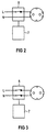
- the corresponding Wiring is shown in Figures 2 and 3. In 4 and 5 is for one or two switched outer conductors L and the side view for one or two neutral conductors of an installation device. Conveniently a two-pole relay is used, as this is the only way pole-independent connection is ensured. With single-pole Switching off would ensure that the outer conductor switched becomes.
- the insertion openings provided as standard on a socket 2 14 for conductors, insofar as they are attached to the module are not available for external wiring covered by covers 13 to avoid partial connections.
- the shutdown device 5 according to FIG 1 can also be used as a semiconductor switch be based on SiC. Such Shutdown device works without sparking.
Landscapes
- Measuring Temperature Or Quantity Of Heat (AREA)
Priority Applications (2)
| Application Number | Priority Date | Filing Date | Title |
|---|---|---|---|
| EP98115548A EP0982812A1 (fr) | 1998-08-18 | 1998-08-18 | Appareil d'installation électrique ayant un dispositif de surveillance de température |
| NO993990A NO993990L (no) | 1998-08-18 | 1999-08-18 | Elektrisk installasjonsanordning med temperaturovervåkningsinnretning |
Applications Claiming Priority (1)
| Application Number | Priority Date | Filing Date | Title |
|---|---|---|---|
| EP98115548A EP0982812A1 (fr) | 1998-08-18 | 1998-08-18 | Appareil d'installation électrique ayant un dispositif de surveillance de température |
Publications (1)
| Publication Number | Publication Date |
|---|---|
| EP0982812A1 true EP0982812A1 (fr) | 2000-03-01 |
Family
ID=8232477
Family Applications (1)
| Application Number | Title | Priority Date | Filing Date |
|---|---|---|---|
| EP98115548A Withdrawn EP0982812A1 (fr) | 1998-08-18 | 1998-08-18 | Appareil d'installation électrique ayant un dispositif de surveillance de température |
Country Status (2)
| Country | Link |
|---|---|
| EP (1) | EP0982812A1 (fr) |
| NO (1) | NO993990L (fr) |
Cited By (2)
| Publication number | Priority date | Publication date | Assignee | Title |
|---|---|---|---|---|
| DE102010053291B4 (de) * | 2010-12-02 | 2013-07-18 | Abb Ag | Installationsschaltgerät mit einer Federzugklemme |
| DE102018114619B4 (de) | 2017-07-17 | 2023-03-30 | Electro Terminal GmbH & Co. KG | Klenuneneinheit, eine elektrische oder elektronische Einheit und eine Steuerungseinheit |
Citations (4)
| Publication number | Priority date | Publication date | Assignee | Title |
|---|---|---|---|---|
| EP0193732A1 (fr) * | 1985-02-20 | 1986-09-10 | Licentia Patent-Verwaltungs-GmbH | Dispositif pour surveiller et contrôler des commutateurs et des combinaisons de commutateurs |
| EP0437696A1 (fr) * | 1990-01-12 | 1991-07-24 | Gebrüder Merten Gmbh & Co. Kg | Dispositif de connexion commuable à distance |
| EP0708498A1 (fr) * | 1994-10-17 | 1996-04-24 | Nisso Industry Co., Ltd. | Dispositif à prise et cordon d'extension |
| DE19514580A1 (de) * | 1995-04-20 | 1996-10-24 | Rainer Dipl Phys Berthold | Leitungsschutzschalter mit einer Einrichtung zur unterscheidenden Erkennung von Kurzschluß- und Überlastabschaltungen |
-
1998
- 1998-08-18 EP EP98115548A patent/EP0982812A1/fr not_active Withdrawn
-
1999
- 1999-08-18 NO NO993990A patent/NO993990L/no unknown
Patent Citations (4)
| Publication number | Priority date | Publication date | Assignee | Title |
|---|---|---|---|---|
| EP0193732A1 (fr) * | 1985-02-20 | 1986-09-10 | Licentia Patent-Verwaltungs-GmbH | Dispositif pour surveiller et contrôler des commutateurs et des combinaisons de commutateurs |
| EP0437696A1 (fr) * | 1990-01-12 | 1991-07-24 | Gebrüder Merten Gmbh & Co. Kg | Dispositif de connexion commuable à distance |
| EP0708498A1 (fr) * | 1994-10-17 | 1996-04-24 | Nisso Industry Co., Ltd. | Dispositif à prise et cordon d'extension |
| DE19514580A1 (de) * | 1995-04-20 | 1996-10-24 | Rainer Dipl Phys Berthold | Leitungsschutzschalter mit einer Einrichtung zur unterscheidenden Erkennung von Kurzschluß- und Überlastabschaltungen |
Cited By (3)
| Publication number | Priority date | Publication date | Assignee | Title |
|---|---|---|---|---|
| DE102010053291B4 (de) * | 2010-12-02 | 2013-07-18 | Abb Ag | Installationsschaltgerät mit einer Federzugklemme |
| DE102018114619B4 (de) | 2017-07-17 | 2023-03-30 | Electro Terminal GmbH & Co. KG | Klenuneneinheit, eine elektrische oder elektronische Einheit und eine Steuerungseinheit |
| DE102018114619B8 (de) | 2017-07-17 | 2023-05-25 | Electro Terminal GmbH & Co. KG | Klemmeneinheit, eine elektrische oder elektronische Einheit und eine Steuerungseinheit |
Also Published As
| Publication number | Publication date |
|---|---|
| NO993990L (no) | 2000-02-21 |
| NO993990D0 (no) | 1999-08-18 |
Similar Documents
| Publication | Publication Date | Title |
|---|---|---|
| EP2107589B1 (fr) | Dispositif de commutation destiné à la mise à la terre d'un onduleur | |
| EP0088390B1 (fr) | Dispositif de protection pour des appareils électriques | |
| EP2256822A2 (fr) | Installation de commutation de sécurité pour installations solaires | |
| DE19960804A1 (de) | Verfahren und Apparat für das Testen eines Leitungskreisunterbrechers für Leitungsstörungen mit Lichtbogenbildung | |
| WO1997026698A1 (fr) | Connecteur, en particulier connecteur a fiche pour reseaux tt et tn | |
| EP2031627B1 (fr) | Unité de construction comprenant un disjoncteur à courant de défaut et un appareil de protection contre les surtensions | |
| DE10041780A1 (de) | Schaltungsunterbrecher | |
| EP0074380A1 (fr) | Dispositif de protection contre les surtensions pour les installations electriques domestiques | |
| DE69706155T2 (de) | Sicherheitsadapter für nicht-geerdete steckdose | |
| EP3726560A1 (fr) | Disjoncteur de protection compact | |
| EP0497752B1 (fr) | Dispositif de débranchement pour dérivateurs de surtension | |
| DE102019103036B4 (de) | Ladesäule mit einem Kombi-Schaltmodul | |
| EP2983191B1 (fr) | Système de détection d'arcs électriques parasites dans un réseau basse tension | |
| DE102020200993B4 (de) | Fernantrieb, Anordnung mit einem Fernantrieb sowie Verfahren | |
| DE3604118A1 (de) | Personenschutzschaltung fuer elektrische geraete | |
| EP2140470B1 (fr) | Module avec extension automatique d'un circuit de controle | |
| DE102009031224B3 (de) | Geräteschalter für elektrisch gebremste Elektrowerkzeuge | |
| CN220066105U (zh) | 一种便于接线的负荷开关 | |
| KR101939927B1 (ko) | 플러그 | |
| DE3412273A1 (de) | Leitungsschutzschalter mit differenzstromausloesung | |
| DE102013104006B3 (de) | Schutzleiterkontaktiersystem | |
| AT384913B (de) | Schutzkontakt-sicherungsstecker | |
| AT413168B (de) | Fehlerstrom-schutzeinrichtung mit netzspannungsabhängiger fehlerstromauslösung und hohem eigenschaltvermögen | |
| DE3641083A1 (de) | Steckvorrichtung mit schutzschaltung | |
| DE10017513A1 (de) | Elektrische Sicherung und elektrisches Steuergerät |
Legal Events
| Date | Code | Title | Description |
|---|---|---|---|
| PUAI | Public reference made under article 153(3) epc to a published international application that has entered the european phase |
Free format text: ORIGINAL CODE: 0009012 |
|
| AK | Designated contracting states |
Kind code of ref document: A1 Designated state(s): AT BE CH DE DK ES FI FR GR IT LI PT SE |
|
| AX | Request for extension of the european patent |
Free format text: AL;LT;LV;MK;RO;SI |
|
| 17P | Request for examination filed |
Effective date: 20000630 |
|
| AKX | Designation fees paid |
Free format text: AT BE CH DE DK ES FI FR GR IT LI PT SE |
|
| STAA | Information on the status of an ep patent application or granted ep patent |
Free format text: STATUS: THE APPLICATION IS DEEMED TO BE WITHDRAWN |
|
| 18D | Application deemed to be withdrawn |
Effective date: 20040302 |