EP0982960A1 - Funkkommunikationsnetz Testverfahren und entsprechende Vorrichtung und Basisstation - Google Patents
Funkkommunikationsnetz Testverfahren und entsprechende Vorrichtung und Basisstation Download PDFInfo
- Publication number
- EP0982960A1 EP0982960A1 EP99460053A EP99460053A EP0982960A1 EP 0982960 A1 EP0982960 A1 EP 0982960A1 EP 99460053 A EP99460053 A EP 99460053A EP 99460053 A EP99460053 A EP 99460053A EP 0982960 A1 EP0982960 A1 EP 0982960A1
- Authority
- EP
- European Patent Office
- Prior art keywords
- signals
- reception
- base station
- jammer
- interference
- Prior art date
- Legal status (The legal status is an assumption and is not a legal conclusion. Google has not performed a legal analysis and makes no representation as to the accuracy of the status listed.)
- Granted
Links
Images
Classifications
-
- H—ELECTRICITY
- H04—ELECTRIC COMMUNICATION TECHNIQUE
- H04W—WIRELESS COMMUNICATION NETWORKS
- H04W16/00—Network planning, e.g. coverage or traffic planning tools; Network deployment, e.g. resource partitioning or cells structures
- H04W16/24—Cell structures
- H04W16/28—Cell structures using beam steering
-
- H—ELECTRICITY
- H01—ELECTRIC ELEMENTS
- H01Q—ANTENNAS, i.e. RADIO AERIALS
- H01Q1/00—Details of, or arrangements associated with, antennas
- H01Q1/12—Supports; Mounting means
- H01Q1/22—Supports; Mounting means by structural association with other equipment or articles
- H01Q1/24—Supports; Mounting means by structural association with other equipment or articles with receiving set
- H01Q1/241—Supports; Mounting means by structural association with other equipment or articles with receiving set used in mobile communications, e.g. GSM
- H01Q1/246—Supports; Mounting means by structural association with other equipment or articles with receiving set used in mobile communications, e.g. GSM specially adapted for base stations
Definitions
- the field of the invention is that of radiocommunication systems with mobile.
- the invention applies in particular, but not exclusively, in systems UMTS type radio communication (for "Universal Mobile Telecommunication System - 2 GHz "in English) or GSM 900 (for" Global System for Mobile- 900 MHz “ in English or "Public Mobile Radio Systems Special Group operating in the 900 MHz band "), DCS 1800 (for” Digital Cellular System - 1800 MHz “in English) or PCS 1900 (for” Personal Communication System - 1900 MHz "in English).
- the present invention relates to a method for testing a network. of radio communication consisting in detecting and elucidating interference between at least two transmitters, namely on the one hand a mobile station, transmitting useful signals in direction of a base station, and on the other hand at least one jammer, transmitting interference signals also in the direction of the base station.
- a radiocommunication system includes a plurality of base stations, each providing radio coverage for a separate geographic unit.
- jammer means any type of device transmitting towards a base station with which the given mobile station communicates, signals having at least certain characteristics identical or similar to those of the signals from the given mobile station.
- the mobile station is sometimes called the terminal radiocommunication, mobile radiotelephone, mobile phone or terminal mobile radio.
- a mobile station is physical equipment used by a user of a radiocommunication system network to access, via a basic, telecommunications services offered.
- a base station covers a geographical area data (or cell) in which a plurality of mobile stations can move with which the base station can exchange signals.
- a base station comprises at least one antenna intended to receive and / or transmit signals from and / or to a plurality of mobile stations.
- Signals exchanged between a mobile station and the base station may be subject to interference that can generate a partial or even total loss of information vehicles. It is recalled that the interference phenomena are caused in particular when signals of identical or similar characteristics are involved in a same propagation medium.
- identical or similar characteristics is meant by example the same frequency, the same code or the same time interval, depending on whether the system implements respectively frequency multiplexing (or FDMA, for "Frequency Division Multiple Access” in English or “Multiple Access by Distribution in Fréquence "in French), by code (or CDMA, for" Coded Division Multiple Access "in English or “Multiple Access by Distribution in Code” in French) or temporal (or TDMA, for "Time Division Multiple Access” in English or “Multiple Access by Distribution in Temps "in French).
- the interference is due to the presence of minus a jammer transmitting signals (called “interference") which disturb the signals (called “useful”) transmitted by a mobile station. It will therefore be understood that such disturbances can cause crucial problems with reception quality and of signals transmitted by a mobile station and intended for a base station.
- the object of the present invention is in particular to overcome this drawback of the state of the art.
- one of the objectives of the present invention is to provide a method of testing a radio network for detecting the presence at least one jammer.
- An additional objective of the invention is to provide such a method allowing to determine the possible nature of the jammer (s).
- Another object of the invention is to provide such a method which can be implemented works without any modification of the signals exchanged between a mobile station and a base station.
- Another object of the invention is to provide such a method which can be implemented work, without any material modification of the existing mobile stations, nor, possibly base stations.
- Another object of the invention is to provide a device allowing the implementation implementation of such a test method for a radiocommunication network.
- Another object of the invention is to provide a base station enabling the implementation of such a test method for a radiocommunication network.
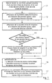
- the general principle of the invention therefore rests on the simultaneous focusing of several radio receiving beams (one per antenna) respectively on different signal sources (i.e. a useful signal source and one or more possible source (s) of interference signals). So at least one reception chain is assigned to the processing of possible interference signals.
- first antenna is used and “second” antenna (called “intelligent” antenna). to simplify the understanding of the invention. It is clear however that it is not compulsory that there are as many antennas that there are reception chains. The same antenna can supply several (or even all) reception chains. In other words, the first and second antennas can form a single antenna.
- an antenna associated with a reception chain forms a beam radio receiving radiator, which can be oriented in elevation (i.e. the angle formed by the line connecting the mobile station to the antenna with the horizontal plane containing the antenna support) and / or azimuth (i.e. the angle formed between a reference line in the horizontal plane containing the antenna support and the projection, direction perpendicular to this horizontal plane, of the line connecting the antenna to the mobile station).
- the nature of the jammer (s) may be arbitrary, and may in particular correspond to that of an emitter (s) foreign to any network of radiocommunication.
- the method of the invention constitutes a technique for detecting imperfections in the radio network concerned.
- this reflects poor management of the distribution of resources such as a double assignment of the same resource. This is for example the case of two base stations neighbors (or relatively close) who both use at least the same communication parameter, such as a frequency, a code, a time interval, ..., to each communicate with a separate mobile station.
- the first and second antennas constitute only one and same antenna.
- the invention also relates to a base station for detecting and elucidating interference between at least two transmitters, namely on the one hand a mobile station transmitting useful signals towards said base station, and on the other hand at least a jammer transmitting interference signals also towards said station based.
- said base station comprises the device for testing a network radio communication described above.
- certain elements are elements already included in the base station to allow the latter to communicate with the mobile stations. In this case, it there is a strong synergy and the cost of the test device is therefore reduced to only the elements not already included in the base station.
- the invention therefore relates to a method and a device for testing a network of radio communication consisting in detecting and elucidating interference between at least two transmitters, namely a mobile station transmitting useful signals towards a base station and at least one jammer transmitting interference signals also in base station management.
- a single jammer B transmits interference signals which interfere with wanted signals from a MS mobile station being communication with a BTS base station. It is clear, however, that the process of the invention can simultaneously allow the detection of a plurality of jammers, in for example using a plurality of reception chains (each allowing to detect a jammer). These different signals (useful and interference) are received via separate radio receiving beams.
- a single antenna can be connected to the two signal reception channels (useful and scrambling).
- the single antenna constitutes the material part and the two reception chains are managed by means software.
- the radiocommunication system cellular to which the base station and the mobile station belong is of the UMTS type and using FDD-WCDMA multiplexing at the frequency of 2 GHz.
- W-CDMA mode for "Wide band Code Division Multiple Access” in English
- ETSI decision of January 1998 concerning UMTS (“Universal Mobile Telecommunication System "), this decision being inserted here by reference. effect that the UMTS radio interface was broadly stopped in January 1998.
- W-CDMA mode uses CDMA access on a 5 MHz channel.
- the base station and the mobile station can also be understood in systems for example of the GSM 900 or DCS 1800 type or even of the type PCS 1900 ...
- the method further comprises a step (17) display of the identifier or the absence of an identifier for the jammer and / or the direction of arrival of the interference signals.
- a step (17) display of the identifier or the absence of an identifier for the jammer and / or the direction of arrival of the interference signals An operator who uses the the invention thus visualizes the nature of the jammer and / or the precise origin of the interference.
- Such a method allows, for a given communication, not only to detect the presence of a jammer in the cell associated with the base station concerned (or in an environment close to this cell), but also to provide information the operator in the area where the jammer is located.
- This area includes in particular the area covered by the associated receiving radioelectric beam to the corresponding reception chain (i.e. either the first or the second chain reception).
- the reception quality by the base station of the useful signals transmitted by the mobile station can then be improved.
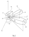
- a base station 21 is located at a site 20 defining the center of a cell data assigned to it, in which it can receive and transmit signals.
- a device 22 for testing a radiocommunication network is placed on the same site 20 than that of the base station 21, for example at the origin O of the three-dimensional coordinate system (Ox, Oy, Oz).
- Such a device 22 is intended to implement the method described previously, in order to detect and elucidate interference between two transmitters, knowing on the one hand a mobile station (MS) 24 transmitting useful signals towards the base station 21 and on the other hand a jammer (B) 23 transmitting interference signals also towards base station 21.
- MS mobile station
- B jammer
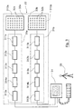
- the device 22 includes two intelligent directional antennas 310a, 310b as explained in detail below (see Figure 3).
- a directive smart antenna or smart antenna with beam adaptation (“Adaptive Smart Antennas”), includes a network of elements radiant distributed matrically on a support (or panel).
- the network of elements radiant is composed of a plurality of columns of radiating elements, controlled generally each independently of the others, so as to form a bundle according to a given azimuth.
- the device 22 for testing a radiocommunication network controls the antennas 310a, 310b, so that these generate two radiating beams 25, 26 radio directional, and oriented in azimuth, towards mobile station 24 and the possible jammer 23.
- a first radiation pattern 26 of the antenna 310b is pointed (or even focused) on the mobile station 24 in communication and a second radiation diagram 25 of the antenna 310a is pointed to the possible jammer 23.
- the radio reception beams 25, 26 can therefore be oriented in azimuth and in elevation, according to two pairs of angles ( ⁇ 1 ; ⁇ 1 ) and ( ⁇ 1 ; ⁇ 2 ) respectively, with ⁇ 1 and ⁇ 2 the angles d 'azimuth, and ⁇ 1 and ⁇ 2 the elevation angles.
- the pairs of angles ( ⁇ 1 ; ⁇ 1 ) and ( ⁇ 2 ; ⁇ 2 ) represent two distinct directions of arrival of the wanted signals and the interference signals.
- the jammer 23 can be an element belonging to the radiocommunication which includes mobile station 24 and base station 21. It can therefore be a neighboring mobile station or base station. Jammer 23 can also be a foreign element in the radiocommunication network.
- the device 22 further comprises means 34 for displaying the identifier or the absence of the jammer 23 identifier and / or the direction of arrival of the interference.
- An operator 35 can consult the results of the search for jammer (s) for a given communication between the mobile station 24 and the base station 21 which uses the device 21 described above.
- the operator 35 can, as soon as he is informed (for example by display), modify the or the corresponding communication parameter (s) to eliminate interference. he may in particular be an intervention at a neighboring base station presenting an anomaly or a defective mobile station, some of which characteristics (and in particular those influencing the signals exchanged) are to be modified.
- the information available on the jammer i.e. its angular position by report to the base station
- the competent authorities responsible for mittees allocation of resources, police, etc.
- the device 22 for testing a network of radio communication described above is included in the base station 21 of the radiocommunication, and reuse part of the means constituting the latter.
- the base station is of the type implementing a spatial multiplexing (or "SDMA” for "Spatial Division Multiple Access” in English or “Multiple Access to Distribution in Space” in French), so it uses in particular a radioelectric receiving beam directional and orientable using means electronic, so as to "follow" the mobile station during its movement within the cell, to communicate with her.
- the base station therefore comprises at least one first intelligent directive antenna 310a and a reception chain 3 la as described previously, to communicate with the mobile station during communication. So, just add a second smart directive antenna and a second chain reception at the base station, unless certain means (in particular decoding and / or reading) of this second chain can be shared with the test device of a radiocommunication network.
- the base station is not of the type setting up performs spatial multiplexing, and implements for example frequency multiplexing (or FDMA) or a time division multiplexing (or TDMA) or even by code (or CDMA), then it is necessary to build the test device according to the invention to provide at at least two additional smart antennas and at least some of the different reception chains (in particular means of allocation of the different reception channels, decoding means and decision-making means).
- FDMA frequency multiplexing
- TDMA time division multiplexing
- CDMA code
Landscapes
- Engineering & Computer Science (AREA)
- Computer Networks & Wireless Communication (AREA)
- Signal Processing (AREA)
- Mobile Radio Communication Systems (AREA)
- Monitoring And Testing Of Transmission In General (AREA)
Applications Claiming Priority (2)
| Application Number | Priority Date | Filing Date | Title |
|---|---|---|---|
| FR9810846 | 1998-08-26 | ||
| FR9810846A FR2782882B1 (fr) | 1998-08-26 | 1998-08-26 | Procede de test d'un reseau de radiocommunication, dispositif et station de correspondants |
Publications (2)
| Publication Number | Publication Date |
|---|---|
| EP0982960A1 true EP0982960A1 (de) | 2000-03-01 |
| EP0982960B1 EP0982960B1 (de) | 2006-07-12 |
Family
ID=9529976
Family Applications (1)
| Application Number | Title | Priority Date | Filing Date |
|---|---|---|---|
| EP99460053A Expired - Lifetime EP0982960B1 (de) | 1998-08-26 | 1999-08-25 | Funkkommunikationsnetz Testverfahren und entsprechende Vorrichtung und Basisstation |
Country Status (6)
| Country | Link |
|---|---|
| US (1) | US6487245B1 (de) |
| EP (1) | EP0982960B1 (de) |
| AT (1) | ATE333196T1 (de) |
| DE (1) | DE69932295T2 (de) |
| ES (1) | ES2268840T3 (de) |
| FR (1) | FR2782882B1 (de) |
Families Citing this family (3)
| Publication number | Priority date | Publication date | Assignee | Title |
|---|---|---|---|---|
| US6795409B1 (en) * | 2000-09-29 | 2004-09-21 | Arraycomm, Inc. | Cooperative polling in a wireless data communication system having smart antenna processing |
| US7043259B1 (en) * | 2000-09-29 | 2006-05-09 | Arraycomm, Inc. | Repetitive paging from a wireless data base station having a smart antenna system |
| JP4159273B2 (ja) * | 2001-09-13 | 2008-10-01 | アルパイン株式会社 | 放送受信装置及びチャネルスキャン方法 |
Citations (1)
| Publication number | Priority date | Publication date | Assignee | Title |
|---|---|---|---|---|
| EP0647978A2 (de) * | 1993-08-12 | 1995-04-12 | Nortel Networks Corporation | Antenneneinrichtung für Basisstation |
Family Cites Families (7)
| Publication number | Priority date | Publication date | Assignee | Title |
|---|---|---|---|---|
| US4584716A (en) * | 1984-11-13 | 1986-04-22 | Honeywell Inc. | Automatic dual diversity receiver |
| JP3033308B2 (ja) * | 1991-12-25 | 2000-04-17 | 松下電器産業株式会社 | 合成ダイバーシチ受信機 |
| US5325403A (en) * | 1992-12-09 | 1994-06-28 | Motorola, Inc. | Method and apparatus for dual-channel diversity reception of a radio signal |
| US6173014B1 (en) * | 1994-08-02 | 2001-01-09 | Telefonaktiebolaget Lm Ericsson | Method of and apparatus for interference rejection combining and downlink beamforming in a cellular radio communications system |
| JPH10247869A (ja) * | 1997-03-04 | 1998-09-14 | Nec Corp | ダイバーシティ回路 |
| US6108389A (en) * | 1997-12-11 | 2000-08-22 | Motorola, Inc. | Synchronization of internal coder-decoders of multiple microprocessors |
| US6236844B1 (en) * | 1998-06-23 | 2001-05-22 | Visteon Global Technologies, Inc. | Proportional diversity radio receiver system |
-
1998
- 1998-08-26 FR FR9810846A patent/FR2782882B1/fr not_active Expired - Fee Related
-
1999
- 1999-08-25 AT AT99460053T patent/ATE333196T1/de not_active IP Right Cessation
- 1999-08-25 DE DE69932295T patent/DE69932295T2/de not_active Expired - Lifetime
- 1999-08-25 EP EP99460053A patent/EP0982960B1/de not_active Expired - Lifetime
- 1999-08-25 US US09/383,024 patent/US6487245B1/en not_active Expired - Lifetime
- 1999-08-25 ES ES99460053T patent/ES2268840T3/es not_active Expired - Lifetime
Patent Citations (1)
| Publication number | Priority date | Publication date | Assignee | Title |
|---|---|---|---|---|
| EP0647978A2 (de) * | 1993-08-12 | 1995-04-12 | Nortel Networks Corporation | Antenneneinrichtung für Basisstation |
Also Published As
| Publication number | Publication date |
|---|---|
| FR2782882A1 (fr) | 2000-03-03 |
| FR2782882B1 (fr) | 2000-10-20 |
| DE69932295T2 (de) | 2007-07-19 |
| US6487245B1 (en) | 2002-11-26 |
| ES2268840T3 (es) | 2007-03-16 |
| DE69932295D1 (de) | 2006-08-24 |
| EP0982960B1 (de) | 2006-07-12 |
| ATE333196T1 (de) | 2006-08-15 |
Similar Documents
| Publication | Publication Date | Title |
|---|---|---|
| JP4457120B2 (ja) | 広角度アンテナローブ | |
| EP0960451B1 (de) | Verfahren und vorrichtung zur richtfunkübertragung | |
| EP2567472B1 (de) | Terristrisch-satelliten hybridsystem für zellulare drahtlose kommunikation mit hohem kapazität | |
| CA2720190C (en) | Systems and methods for segmenting a satellite field of view for detecting radio frequency signals | |
| US9853668B2 (en) | Wideband beamformer system | |
| RU2227371C2 (ru) | Высокоэффективная суборбитальная высотная телекоммуникационная система и способ создания беспроводных телекоммуникаций | |
| JPH08510609A (ja) | 周波数再利用を改善したセルラー/衛星通信システム | |
| FR2757004A1 (fr) | Procede et systeme pour l'optimisation d'un canal de trafic dans un systeme de communication sans fil | |
| KR20070013297A (ko) | 지상 셀룰러 주파수 스펙트럼의 공간 기반의 재사용을 위한시스템들 및 방법들 | |
| KR19990082079A (ko) | 선택된 다중 다이버시티 수신을 이용한 셀룰러 무선전화 기지국의 방법 및 장치 | |
| FR2655220A1 (fr) | Systeme de communication de zone. | |
| FR2677198A1 (fr) | Procede et dispositif d'amelioration de la qualite d'un signal de telecommunication. | |
| EP0977380A1 (de) | Zellulares Funkkommunikationssystem unter verwendung von Datenwiederholung in Abwärtsrichtung von einer Basistation und Datenrelais dafür | |
| EP0982960B1 (de) | Funkkommunikationsnetz Testverfahren und entsprechende Vorrichtung und Basisstation | |
| EP3641156B1 (de) | Satellitenkommunikationssystem zur übertragung eines bitstroms damit | |
| EP0971438A1 (de) | Verfahren zur Steuerung von Strahlungskeulen für die Kommunikation zwischen einer Basisstation und einem mobilem Funktelefon sowie zugehörige Basisstation | |
| CA2629891C (fr) | Systeme d'antennes d'emission adaptatives aux conditions de propagation pour diffusion radioelectrique | |
| CN1328725A (zh) | 在公共数据信道上发送公共信息的装置和方法 | |
| EP1253799A1 (de) | Verfahren und Einrichtung zur Positionsbestimmung einer mobilen Station in einem Kommunikationsnetzwerk | |
| US20040248512A1 (en) | Satellite communication method and system | |
| EP0865220A1 (de) | Verfahren zur Zellenkonfiguration in einem digitalen zellularen Funkkommunikationssystem | |
| EP0767550A1 (de) | Interbandfrequenzsprungverfahren in einer zellulare Funkkommunikationsanordnung mit mobilen Stationen und Stationen dafür | |
| US12556233B1 (en) | System for reducing duplicate signaling in a wireless network | |
| US11626915B1 (en) | Dynamic beam pattern management of one or more antenna elements of an antenna array | |
| Cohen et al. | Frequency sharing between LEO systems |
Legal Events
| Date | Code | Title | Description |
|---|---|---|---|
| PUAI | Public reference made under article 153(3) epc to a published international application that has entered the european phase |
Free format text: ORIGINAL CODE: 0009012 |
|
| AK | Designated contracting states |
Kind code of ref document: A1 Designated state(s): AT BE CH CY DE DK ES FI FR GB GR IE IT LI LU MC NL PT SE |
|
| AX | Request for extension of the european patent |
Free format text: AL;LT;LV;MK;RO;SI |
|
| 17P | Request for examination filed |
Effective date: 20000608 |
|
| AKX | Designation fees paid |
Free format text: AT BE CH CY DE DK ES FI FR GB GR IE IT LI LU MC NL PT SE |
|
| 17Q | First examination report despatched |
Effective date: 20040112 |
|
| RAP1 | Party data changed (applicant data changed or rights of an application transferred) |
Owner name: COMPAGNIE FINANCIERE POUR LE RADIOTELEPHONE SA |
|
| RAP1 | Party data changed (applicant data changed or rights of an application transferred) |
Owner name: CEGETEL GROUPE |
|
| RAP1 | Party data changed (applicant data changed or rights of an application transferred) |
Owner name: SOCIETE FRANEAISE DU RADIOTELEPHONE-SFR |
|
| GRAP | Despatch of communication of intention to grant a patent |
Free format text: ORIGINAL CODE: EPIDOSNIGR1 |
|
| GRAS | Grant fee paid |
Free format text: ORIGINAL CODE: EPIDOSNIGR3 |
|
| GRAA | (expected) grant |
Free format text: ORIGINAL CODE: 0009210 |
|
| AK | Designated contracting states |
Kind code of ref document: B1 Designated state(s): AT BE CH CY DE DK ES FI FR GB GR IE IT LI LU MC NL PT SE |
|
| PG25 | Lapsed in a contracting state [announced via postgrant information from national office to epo] |
Ref country code: NL Free format text: LAPSE BECAUSE OF FAILURE TO SUBMIT A TRANSLATION OF THE DESCRIPTION OR TO PAY THE FEE WITHIN THE PRESCRIBED TIME-LIMIT Effective date: 20060712 Ref country code: IE Free format text: LAPSE BECAUSE OF FAILURE TO SUBMIT A TRANSLATION OF THE DESCRIPTION OR TO PAY THE FEE WITHIN THE PRESCRIBED TIME-LIMIT Effective date: 20060712 Ref country code: FI Free format text: LAPSE BECAUSE OF FAILURE TO SUBMIT A TRANSLATION OF THE DESCRIPTION OR TO PAY THE FEE WITHIN THE PRESCRIBED TIME-LIMIT Effective date: 20060712 Ref country code: AT Free format text: LAPSE BECAUSE OF FAILURE TO SUBMIT A TRANSLATION OF THE DESCRIPTION OR TO PAY THE FEE WITHIN THE PRESCRIBED TIME-LIMIT Effective date: 20060712 |
|
| REG | Reference to a national code |
Ref country code: GB Ref legal event code: FG4D Free format text: NOT ENGLISH |
|
| REG | Reference to a national code |
Ref country code: CH Ref legal event code: EP |
|
| REG | Reference to a national code |
Ref country code: IE Ref legal event code: FG4D Free format text: LANGUAGE OF EP DOCUMENT: FRENCH |
|
| REF | Corresponds to: |
Ref document number: 69932295 Country of ref document: DE Date of ref document: 20060824 Kind code of ref document: P |
|
| PG25 | Lapsed in a contracting state [announced via postgrant information from national office to epo] |
Ref country code: SE Free format text: LAPSE BECAUSE OF FAILURE TO SUBMIT A TRANSLATION OF THE DESCRIPTION OR TO PAY THE FEE WITHIN THE PRESCRIBED TIME-LIMIT Effective date: 20061012 Ref country code: DK Free format text: LAPSE BECAUSE OF FAILURE TO SUBMIT A TRANSLATION OF THE DESCRIPTION OR TO PAY THE FEE WITHIN THE PRESCRIBED TIME-LIMIT Effective date: 20061012 |
|
| REG | Reference to a national code |
Ref country code: CH Ref legal event code: NV Representative=s name: E. BLUM & CO. PATENTANWAELTE |
|
| GBT | Gb: translation of ep patent filed (gb section 77(6)(a)/1977) |
Effective date: 20061012 |
|
| PG25 | Lapsed in a contracting state [announced via postgrant information from national office to epo] |
Ref country code: PT Free format text: LAPSE BECAUSE OF FAILURE TO SUBMIT A TRANSLATION OF THE DESCRIPTION OR TO PAY THE FEE WITHIN THE PRESCRIBED TIME-LIMIT Effective date: 20061212 |
|
| NLV1 | Nl: lapsed or annulled due to failure to fulfill the requirements of art. 29p and 29m of the patents act | ||
| REG | Reference to a national code |
Ref country code: ES Ref legal event code: FG2A Ref document number: 2268840 Country of ref document: ES Kind code of ref document: T3 |
|
| PLBE | No opposition filed within time limit |
Free format text: ORIGINAL CODE: 0009261 |
|
| STAA | Information on the status of an ep patent application or granted ep patent |
Free format text: STATUS: NO OPPOSITION FILED WITHIN TIME LIMIT |
|
| 26N | No opposition filed |
Effective date: 20070413 |
|
| REG | Reference to a national code |
Ref country code: CH Ref legal event code: PFA Owner name: SOCIETE FRANCAISE DU RADIOTELEPHONE-SFR Free format text: SOCIETE FRANCAISE DU RADIOTELEPHONE-SFR#42, AVENUE DE FRIEDLAND#75008 PARIS (FR) -TRANSFER TO- SOCIETE FRANCAISE DU RADIOTELEPHONE-SFR#42, AVENUE DE FRIEDLAND#75008 PARIS (FR) |
|
| REG | Reference to a national code |
Ref country code: HK Ref legal event code: WD Ref document number: 1026995 Country of ref document: HK |
|
| PG25 | Lapsed in a contracting state [announced via postgrant information from national office to epo] |
Ref country code: GR Free format text: LAPSE BECAUSE OF FAILURE TO SUBMIT A TRANSLATION OF THE DESCRIPTION OR TO PAY THE FEE WITHIN THE PRESCRIBED TIME-LIMIT Effective date: 20061013 |
|
| PG25 | Lapsed in a contracting state [announced via postgrant information from national office to epo] |
Ref country code: CY Free format text: LAPSE BECAUSE OF FAILURE TO SUBMIT A TRANSLATION OF THE DESCRIPTION OR TO PAY THE FEE WITHIN THE PRESCRIBED TIME-LIMIT Effective date: 20060712 |
|
| REG | Reference to a national code |
Ref country code: FR Ref legal event code: GC Effective date: 20150310 |
|
| REG | Reference to a national code |
Ref country code: FR Ref legal event code: PLFP Year of fee payment: 18 |
|
| REG | Reference to a national code |
Ref country code: FR Ref legal event code: PLFP Year of fee payment: 19 |
|
| REG | Reference to a national code |
Ref country code: FR Ref legal event code: GC Effective date: 20180111 |
|
| REG | Reference to a national code |
Ref country code: FR Ref legal event code: PLFP Year of fee payment: 20 |
|
| PGFP | Annual fee paid to national office [announced via postgrant information from national office to epo] |
Ref country code: LU Payment date: 20180724 Year of fee payment: 20 |
|
| PGFP | Annual fee paid to national office [announced via postgrant information from national office to epo] |
Ref country code: DE Payment date: 20180719 Year of fee payment: 20 Ref country code: IT Payment date: 20180719 Year of fee payment: 20 Ref country code: ES Payment date: 20180903 Year of fee payment: 20 Ref country code: FR Payment date: 20180720 Year of fee payment: 20 Ref country code: MC Payment date: 20180726 Year of fee payment: 20 |
|
| PGFP | Annual fee paid to national office [announced via postgrant information from national office to epo] |
Ref country code: GB Payment date: 20180720 Year of fee payment: 20 Ref country code: BE Payment date: 20180724 Year of fee payment: 20 Ref country code: CH Payment date: 20180726 Year of fee payment: 20 |
|
| REG | Reference to a national code |
Ref country code: DE Ref legal event code: R071 Ref document number: 69932295 Country of ref document: DE |
|
| REG | Reference to a national code |
Ref country code: CH Ref legal event code: PL |
|
| REG | Reference to a national code |
Ref country code: GB Ref legal event code: PE20 Expiry date: 20190824 |
|
| REG | Reference to a national code |
Ref country code: BE Ref legal event code: MK Effective date: 20190825 |
|
| PG25 | Lapsed in a contracting state [announced via postgrant information from national office to epo] |
Ref country code: GB Free format text: LAPSE BECAUSE OF EXPIRATION OF PROTECTION Effective date: 20190824 |
|
| REG | Reference to a national code |
Ref country code: ES Ref legal event code: FD2A Effective date: 20201002 |
|
| PG25 | Lapsed in a contracting state [announced via postgrant information from national office to epo] |
Ref country code: ES Free format text: LAPSE BECAUSE OF EXPIRATION OF PROTECTION Effective date: 20190826 |