EP0983809A2 - Méthode et dispositif pour le cintrage d' un profilé creux pour la fabrication d' un cadre intercalaire pour vitrage isolant - Google Patents
Méthode et dispositif pour le cintrage d' un profilé creux pour la fabrication d' un cadre intercalaire pour vitrage isolant Download PDFInfo
- Publication number
- EP0983809A2 EP0983809A2 EP99116593A EP99116593A EP0983809A2 EP 0983809 A2 EP0983809 A2 EP 0983809A2 EP 99116593 A EP99116593 A EP 99116593A EP 99116593 A EP99116593 A EP 99116593A EP 0983809 A2 EP0983809 A2 EP 0983809A2
- Authority
- EP
- European Patent Office
- Prior art keywords
- hollow profile
- bending
- hot air
- abutment
- bending area
- Prior art date
- Legal status (The legal status is an assumption and is not a legal conclusion. Google has not performed a legal analysis and makes no representation as to the accuracy of the status listed.)
- Withdrawn
Links
- 238000005452 bending Methods 0.000 title claims abstract description 160
- 238000000034 method Methods 0.000 title claims abstract description 33
- 125000006850 spacer group Chemical group 0.000 title claims description 17
- 229920003023 plastic Polymers 0.000 claims abstract description 36
- 239000004033 plastic Substances 0.000 claims abstract description 36
- 238000010438 heat treatment Methods 0.000 claims abstract description 30
- 229910052751 metal Inorganic materials 0.000 claims description 13
- 239000002184 metal Substances 0.000 claims description 13
- 238000001816 cooling Methods 0.000 claims description 10
- 239000002274 desiccant Substances 0.000 claims description 7
- 239000011521 glass Substances 0.000 claims description 6
- 230000008878 coupling Effects 0.000 claims description 3
- 238000010168 coupling process Methods 0.000 claims description 3
- 238000005859 coupling reaction Methods 0.000 claims description 3
- 238000009826 distribution Methods 0.000 claims description 3
- 229910052782 aluminium Inorganic materials 0.000 claims description 2
- XAGFODPZIPBFFR-UHFFFAOYSA-N aluminium Chemical compound [Al] XAGFODPZIPBFFR-UHFFFAOYSA-N 0.000 claims description 2
- 238000003825 pressing Methods 0.000 claims description 2
- 238000004804 winding Methods 0.000 claims description 2
- 239000004020 conductor Substances 0.000 claims 1
- 230000008569 process Effects 0.000 abstract description 15
- 239000000463 material Substances 0.000 abstract description 8
- 238000007711 solidification Methods 0.000 abstract description 3
- 230000008023 solidification Effects 0.000 abstract description 3
- 230000002349 favourable effect Effects 0.000 description 3
- 230000007704 transition Effects 0.000 description 3
- 230000006835 compression Effects 0.000 description 2
- 238000007906 compression Methods 0.000 description 2
- 238000004519 manufacturing process Methods 0.000 description 2
- 230000009286 beneficial effect Effects 0.000 description 1
- 230000008901 benefit Effects 0.000 description 1
- 230000009172 bursting Effects 0.000 description 1
- 238000005336 cracking Methods 0.000 description 1
- 230000003111 delayed effect Effects 0.000 description 1
- 230000006872 improvement Effects 0.000 description 1
- 238000009434 installation Methods 0.000 description 1
- 238000009413 insulation Methods 0.000 description 1
- 230000005923 long-lasting effect Effects 0.000 description 1
- 238000002844 melting Methods 0.000 description 1
- 230000008018 melting Effects 0.000 description 1
- 150000002739 metals Chemical class 0.000 description 1
- 229920000642 polymer Polymers 0.000 description 1
- 238000011084 recovery Methods 0.000 description 1
- 238000007493 shaping process Methods 0.000 description 1
Images

Classifications
-
- B—PERFORMING OPERATIONS; TRANSPORTING
- B21—MECHANICAL METAL-WORKING WITHOUT ESSENTIALLY REMOVING MATERIAL; PUNCHING METAL
- B21D—WORKING OR PROCESSING OF SHEET METAL OR METAL TUBES, RODS OR PROFILES WITHOUT ESSENTIALLY REMOVING MATERIAL; PUNCHING METAL
- B21D53/00—Making other particular articles
- B21D53/74—Making other particular articles frames for openings, e.g. for windows, doors, handbags
-
- B—PERFORMING OPERATIONS; TRANSPORTING
- B21—MECHANICAL METAL-WORKING WITHOUT ESSENTIALLY REMOVING MATERIAL; PUNCHING METAL
- B21D—WORKING OR PROCESSING OF SHEET METAL OR METAL TUBES, RODS OR PROFILES WITHOUT ESSENTIALLY REMOVING MATERIAL; PUNCHING METAL
- B21D11/00—Bending not restricted to forms of material mentioned in only one of groups B21D5/00, B21D7/00, B21D9/00; Bending not provided for in groups B21D5/00 - B21D9/00; Twisting
- B21D11/10—Bending specially adapted to produce specific articles, e.g. leaf springs
-
- B—PERFORMING OPERATIONS; TRANSPORTING
- B21—MECHANICAL METAL-WORKING WITHOUT ESSENTIALLY REMOVING MATERIAL; PUNCHING METAL
- B21D—WORKING OR PROCESSING OF SHEET METAL OR METAL TUBES, RODS OR PROFILES WITHOUT ESSENTIALLY REMOVING MATERIAL; PUNCHING METAL
- B21D7/00—Bending rods, profiles, or tubes
- B21D7/16—Auxiliary equipment, e.g. for heating or cooling of bends
- B21D7/162—Heating equipment
-
- B—PERFORMING OPERATIONS; TRANSPORTING
- B29—WORKING OF PLASTICS; WORKING OF SUBSTANCES IN A PLASTIC STATE IN GENERAL
- B29C—SHAPING OR JOINING OF PLASTICS; SHAPING OF MATERIAL IN A PLASTIC STATE, NOT OTHERWISE PROVIDED FOR; AFTER-TREATMENT OF THE SHAPED PRODUCTS, e.g. REPAIRING
- B29C53/00—Shaping by bending, folding, twisting, straightening or flattening; Apparatus therefor
- B29C53/02—Bending or folding
- B29C53/08—Bending or folding of tubes or other profiled members
- B29C53/083—Bending or folding of tubes or other profiled members bending longitudinally, i.e. modifying the curvature of the tube axis
-
- B—PERFORMING OPERATIONS; TRANSPORTING
- B29—WORKING OF PLASTICS; WORKING OF SUBSTANCES IN A PLASTIC STATE IN GENERAL
- B29C—SHAPING OR JOINING OF PLASTICS; SHAPING OF MATERIAL IN A PLASTIC STATE, NOT OTHERWISE PROVIDED FOR; AFTER-TREATMENT OF THE SHAPED PRODUCTS, e.g. REPAIRING
- B29C35/00—Heating, cooling or curing, e.g. crosslinking or vulcanising; Apparatus therefor
- B29C35/02—Heating or curing, e.g. crosslinking or vulcanizing during moulding, e.g. in a mould
- B29C35/04—Heating or curing, e.g. crosslinking or vulcanizing during moulding, e.g. in a mould using liquids, gas or steam
- B29C35/045—Heating or curing, e.g. crosslinking or vulcanizing during moulding, e.g. in a mould using liquids, gas or steam using gas or flames
- B29C2035/046—Heating or curing, e.g. crosslinking or vulcanizing during moulding, e.g. in a mould using liquids, gas or steam using gas or flames dried air
-
- B—PERFORMING OPERATIONS; TRANSPORTING
- B29—WORKING OF PLASTICS; WORKING OF SUBSTANCES IN A PLASTIC STATE IN GENERAL
- B29L—INDEXING SCHEME ASSOCIATED WITH SUBCLASS B29C, RELATING TO PARTICULAR ARTICLES
- B29L2031/00—Other particular articles
- B29L2031/001—Profiled members, e.g. beams, sections
- B29L2031/003—Profiled members, e.g. beams, sections having a profiled transverse cross-section
-
- E—FIXED CONSTRUCTIONS
- E06—DOORS, WINDOWS, SHUTTERS, OR ROLLER BLINDS IN GENERAL; LADDERS
- E06B—FIXED OR MOVABLE CLOSURES FOR OPENINGS IN BUILDINGS, VEHICLES, FENCES OR LIKE ENCLOSURES IN GENERAL, e.g. DOORS, WINDOWS, BLINDS, GATES
- E06B3/00—Window sashes, door leaves, or like elements for closing wall or like openings; Layout of fixed or moving closures, e.g. windows in wall or like openings; Features of rigidly-mounted outer frames relating to the mounting of wing frames
- E06B3/66—Units comprising two or more parallel glass or like panes permanently secured together
- E06B3/673—Assembling the units
- E06B3/67304—Preparing rigid spacer members before assembly
- E06B3/67308—Making spacer frames, e.g. by bending or assembling straight sections
- E06B3/67313—Making spacer frames, e.g. by bending or assembling straight sections by bending
Definitions
- the invention relates to a method for bending a hollow profile, which consists entirely or partially of plastic, at least a metal layer on the crossbar on the outside in the use position can be provided, embedded or arranged on the outside, for Production of a hollow, in particular filled with desiccant Spacer frame for insulating glass panes, the hollow profile fed to a bending device and by means of a clamping device fixed in the feed direction in front of the bending area and the one to be bent Leg of the hollow profile in the feed direction behind the bending area also detected and opposite one located in the bending area Abutment is pivoted and bent.
- the invention further relates to a device for bending a wholly or partially made of plastic hollow profile Production of a filled with desiccant or hollow spacer frames to be filled for insulating glass panes, with an approximately in the feed direction of the hollow profile before Bending area arranged clamping device, which for grasping of the profile area in front of the bend or the bending area serves and especially one on the one hand on an inner Cross bar and on the other hand on an outer cross bar of the hollow profile attacking inner and outer jaw or the like holder has, and with a device for detecting the to be bent Leg as well as with an abutment for fixing the inside the resulting bend or curvature and / or the one running there inner crossbar of the hollow profile, which abutment in Position of use is arranged on the inside in the bending area, in particular to carry out the aforementioned method.
- the method mentioned at the outset is thereby to achieve this object characterized in that the bending area of the hollow profile and / or at least the abutment around which the hollow profile is bent, at least temporarily before and / or when bending to a temperature is heated at which the strength of the hollow profile forming or co-forming plastic is reduced.
- the hollow profile in Bending area and at least the abutment on the softening or Placement temperature of the plastic forming the hollow profile is heated.
- the bending area of the hollow profile is then so compliant and plastic that the desired exact bend quickly and can be carried out precisely, after which the plastic after his cooling then no tendency to spring back into the original Location has more.
- the invention makes use of the fact that Plastics generally do not have an exact melting point, but rather gradually become softer when heated, so that a Heating can be chosen in which the said facilitated and precise bending can be carried out without the hollow profile even in terms of its cross section and dimensions is undesirably deformed in the bending area.
- a particularly expedient and inexpensive procedure can be used consist in that the bending point and the abutment with hot air be blown. This can be a very targeted and insofar energy-saving heating can be carried out without expensive Heaters directly at the bending point or for that Bending essential machine parts must be installed. It appropriate air ducts are sufficient to ensure an exact supply of the hot and To allow hot air to the desired places. It can the actual energy source with the corresponding heating output outside of the often confined space Bending area may be arranged.
- a further improvement of the process can provide that the Hot air through channels or holes in the clamping device for Fixing the hollow profile in front of the bending point approximately parallel to the clamped hollow profile in front of its bending point and is blown out.
- This not only gives the clamping device a double function, but it can also have separate feed lines for the hot air can be avoided.
- the Clamping device to be slightly heated and preheated so that in the intermittent operation, as in the bending of such Spacer frame inevitably occurs because of a corner after the other must be bent, the intermittent supply
- the hot air does not cause the air to be switched on again is unnecessarily cooled on its way to the point to be heated.
- the hot air supply switched on again shows that the heating air then already by a preheated from the previous process Clamping device can be supplied and thereby your desired Retains heating temperature.
- the hot air flow approximately in the feed direction of the workpiece or hollow profile in the Inside of the bend that forms and at the same time against the Abutment directed and thereby the inside of the bend of the Hollow profile is heated.
- the hot air can already during the feeding of the hollow profile in the bending position, fed at least during the last part of this feed and thereby the part located behind and in the bending area of the hollow profile are preheated. So the neighboring areas are also the actual bend and bend somewhat warmer and softer and form transitions to the not softened or plasticized part of the profile, so that corresponding tensile and / or Compression stresses within the material of the hollow profile can be absorbed and balanced.
- the area of the Hollow profile can be softened or plasticized so that it becomes smoother and the bending process correspondingly quick and can be done exactly and with the removal of reset voltages.
- the invention therefore makes use of one or more the knowledge of the measures and procedural steps described above to use that a completely or partially made of plastic Hollow profile can be bent particularly well if the bending area is heated to the extent that the plastic is actually inherent Tensions or resistances that are practically eliminated then stop cooling again.
- a precise bending of the hollow profile be carried out, which then after cooling a accordingly stable and dimensionally stable corner results, so that overall a plastic spacer frame can be created that maintains the desired dimension in the corners and angles better protection against heat transfer than a corresponding one metallic spacer frame is, so avoids cold bridges.
- the device mentioned at the outset is for achieving the object characterized in that in the bending area at least on the inside the bending of the hollow profile a heater for this bending area and / or is provided for the abutment. So that the Bending area to be heated so that a whole or part of it Plastic existing hollow profile with regard to its material becomes softer and more flexible and can be easily bent, without restoring voltages or Reset trends remain. After the cold is one Bending point stable and permanent.
- Hot air heater for the Bending area and the abutment is provided.
- Using hot air can the heating both in terms of temperature and in spatially accurate, without that within the Bending device or the abutment special heaters or Heating devices would have to be installed.
- Hot air can be very simple and targeted feeding.
- the hollow profile in front of the Bending area holding fixture and especially their on clamping jaw or holder lying on the inside of the hollow profile flowed through by the supplied hot air and thereby heated, so that the material of the hollow profile from the heated bending point starting from the sides is still a little warmed up and such a gradual transition to the cold part and area of the Hollow profile results. It is also achieved that after a Interruption of the hot air supply, for example after a new one Feeding the hollow profile the hot air then switched on again flows through a preheated tensioning device and there does not cool down again, so that the processing speed despite that when advancing from one bending area to the next interruption is not delayed. The heat capacity the clamping device is sufficient to cool down too much during to avoid such an interruption, so that then again switched on hot air almost immediately the required Heating temperature.
- Another useful embodiment of the invention Device can be that the jaw or the like a transverse to the hot air channels, in particular, formed as a bore oriented feed opening for the hot air has and a coupling with a bracket is connected, in which a bore or a channel for the Hot air supply is arranged, which is in the use position with the Feed opening of the clamping jaw or the like completely or at least is partially in overlap and that the jaw may be to adapt to different dimensions of the to be bent Hollow profiles is interchangeable.
- the parallel individual channels in particular designed as bores for an even temperature distribution behind the Contact surface of the jaw arranged approximately evenly distributed his. This not only preheats the jaw evenly, but above all, even heating in the bending area over the entire width of the internal crosspiece of the Hollow profile and the abutment located there. Thereby can avoid different temperatures in the bending area that may lead to different bending results could lead across the width of the crossbar. Accordingly, exactly and the bend achieved and its angle over the entire is exact Width of the hollow profile and the spacer frame formed thereby.
- Claim 17 contains features and measures relating to heating the hot air with the help of a heat exchanger, which is preferred as Metal or aluminum block with corresponding channels and Heating elements can be designed.
- Claim 18 relates to the possibility of on the outside of the Bending point made entirely or partially of plastic
- Claim 19 relates to a in the feed direction behind the bending area arranged cooling, through which the softening of the plastic after the bending process can be reversed as quickly as possible.
- Claim 20 specifies a constructive possibility, such as the Compressed air used to generate the hot air can also be used as cooling air can be made.
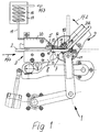
- a device designated as a whole by 1 is used to bend one wholly or partially made of plastic hollow profile 2 and corresponds in structure and mode of operation to what the mechanical parts, such as the device for bending a Hollow profile according to EP 0 318 748 B2 or EP 0 121 873 B1, Figure 1.
- the hollow profile 2 can already during the bending process Desiccant filled or it is then filled with so that it is suitable as a spacer frame for insulating glass panes is. Furthermore, cases are conceivable in which the hollow profile 2 without Desiccant remains.
- This Clamping device 3 has an inner crosspiece 4 of the Hollow profile 2 attacking jaw 5 and one on an outer Crossbar 6 attacking jaw 7 and further is in this area the clamping device 3 also a hold-down 8 for the hollow profile 2 recognizable.
- the device 1 has an overall designated 9 Device for detecting the leg 2a to be bent Hollow profile 2 and an abutment 10 that can be pivoted with it Fix the inside of the resulting bend or curve on.
- the abutment 10 thus acts on the inside of the resulting bend-running inner crossbar 4 of the hollow profile 2.
- a pivotable abutment 10 would also be an abutment according to FIG. 2 of EP 0 121 873 B1 is conceivable.
- the plastic can which is the hollow profile 2, to the extent that they are softened easily deformed without leaving any residual stresses, can also be bent so that after the subsequent Cool the hollow profile 2 has a stable corner. Because this corner is formed in the softened state of the material also exists no risk of bursting or splintering or tearing and in addition, the side webs 11 can be smooth and keep parallel shape and their correct distance so that they later a flat and dense system for the individual panes of one Can form insulating glass.
- a hot air heater for the bending area and the abutment 10 is provided.
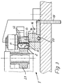
- the hot air is as effective as possible and without any significant cooling is usable, this includes the hot air channels 12 containing Clamping jaw 5 with its end having the mouths 11 up to or close to the abutment 10, which is especially in the figure 2 is clearly recognizable. Since the abutment 10 during its Inflow with hot air at the same time as one of the bending movements corresponding pivoting or twisting according to the curved arrow Pf2 in Figure 2 is performed during the bending also a correspondingly well-warmed area of the abutment 10 in contact with the inner crosspiece 4 of the hollow profile 2 brought. In addition, the inflowing hot air is on directed the place where the abutment 10 and the inner Cross bar 4 come into contact with each other, so that at this point particularly effective heating can take place.
- a heat exchanger 17 for heating of compressed air flowing in according to arrow Pf3 is used by a corresponding winding line 18 a sufficient dwell time has within the heat exchanger 17 to the desired heating temperature to obtain.
- the heat exchanger 17 can be a block of metal be, which contains heating coils and / or heating elements, which in the Drawing is not shown in detail. From this heat exchanger 17 from the heated compressed air passes through a line 19 to the Clamping device 3 and finally through a conduit 20 to the bore 16, which is in register with the feed opening 13.
- the actual heating process is therefore advantageous outside and at a distance from the bending area of the device 1 performed and it can belong to the device 1 parts be used to bring the hot air to the location to be heated bring so that the bending area is not with additional installations must be provided.
- cooling not shown, for example, by means of cold blown air.
- bending is one Hollow profile 2, which consists entirely or partially of plastic possible in which the bending area of the hollow profile 2 and at least the abutting and effective abutment 10, by which the Hollow profile 2 is bent, at least temporarily before and / or at Bending is heated to a temperature at which the Strength of the material forming or forming the hollow profile is so reduced that the bending process is easy and precise and without the risk of splintering or cracking or tearing open of the hollow profile 2 can take place.
- the hollow profile 2 in Bending range expediently to the softening or plasticizing temperature of the plastic heated and the abutment 10 takes on about the same temperature. This happens because the Bending point and the abutment 10 are blown with hot air, what hot air through the channels and holes already described the clamping devices 3 and thereby their jaw 5 fed become.
- the hot air can already during the feed movement of the Hollow profile 2 are blown into its bending position, so that also one located behind the bending area during bending Part of the hollow profile is at least preheated. It follows thereby a gradual move from the bending point to both sides Temperature transition within the hollow profile 2 so that it does not due to damage due to excessive temperature differences.
- the heated material allows those that occur during bending Compression, elongation, deformation and flow movements without thereby noteworthy voltages and in particular reset voltages stay at the bend. After cooling, the corner of the curved plastic profile 2 high strength and dimensional accuracy.
- a bending device 1 For bending a hollow profile 2, which is made entirely or partially Plastic is used, a bending device 1 with a Define hollow profile 2 during the bending in front of the bending area Clamping device 3 and a device 9 for detecting the in Infeed direction behind leg 2a located behind the bending area, this leg 2a to be bent or part to be bent Hollow profile 2 compared to one inside in the bending area arranged abutment 10 is pivoted and bent. Doing so the bending area of the hollow profile 2 and at least the abutment 10 at least temporarily before and / or when bending to a temperature heated, in which the strength forming the hollow profile 2 Material is reduced so that the bending process easily and can be done precisely and after solidification a stable and true-to-size corner is available. It is particularly suitable for heating good on the inside of the bending point and the abutment 10 directed hot air.
Landscapes
- Engineering & Computer Science (AREA)
- Mechanical Engineering (AREA)
- Shaping Of Tube Ends By Bending Or Straightening (AREA)
Applications Claiming Priority (2)
| Application Number | Priority Date | Filing Date | Title |
|---|---|---|---|
| DE1998139444 DE19839444C1 (de) | 1998-08-29 | 1998-08-29 | Verfahren und Vorrichtung zum Biegen eines Hohlprofiles zur Herstellung eines Abstandhalter-Rahmens für Isolierglasscheiben |
| DE19839444 | 1998-08-29 |
Publications (2)
| Publication Number | Publication Date |
|---|---|
| EP0983809A2 true EP0983809A2 (fr) | 2000-03-08 |
| EP0983809A3 EP0983809A3 (fr) | 2000-10-04 |
Family
ID=7879186
Family Applications (1)
| Application Number | Title | Priority Date | Filing Date |
|---|---|---|---|
| EP99116593A Withdrawn EP0983809A3 (fr) | 1998-08-29 | 1999-08-25 | Méthode et dispositif pour le cintrage d' un profilé creux pour la fabrication d' un cadre intercalaire pour vitrage isolant |
Country Status (2)
| Country | Link |
|---|---|
| EP (1) | EP0983809A3 (fr) |
| DE (1) | DE19839444C1 (fr) |
Cited By (2)
| Publication number | Priority date | Publication date | Assignee | Title |
|---|---|---|---|---|
| CN108856563A (zh) * | 2018-07-19 | 2018-11-23 | 北京博驰自动化机械有限公司 | 一种暖边间隔条折弯工艺及设备 |
| FR3074434A1 (fr) * | 2017-12-06 | 2019-06-07 | Meca Theil | Installation et procede de pliage de profiles metalliques d'ouvrants |
Families Citing this family (4)
| Publication number | Priority date | Publication date | Assignee | Title |
|---|---|---|---|---|
| AT410909B (de) * | 2000-05-09 | 2003-08-25 | Lisec Peter | Verfahren und vorrichtung zum biegen von hohlprofilleisten zu abstandhalterrahmen für isolierglasscheiben |
| DE50100881D1 (de) * | 2001-08-20 | 2003-12-04 | Peter Lisec | Verfahren und Vorrichtung zum Biegen von Hohlprofilleisten zu Abstandhalterrahmen für Isolierglasscheiben |
| AT514109B1 (de) * | 2013-04-12 | 2015-02-15 | Progress Maschinen & Automation Ag | Biegemaschine |
| CA2924182C (fr) * | 2015-04-02 | 2022-12-06 | Lombarda Macchine S.A.S. Di G.B. Lattuada & C. | Methode de courbure automatique d'elements espaceurs en vue d'isoler les panneaux de verre a double vitrage et machine servant a mener la methode |
Citations (2)
| Publication number | Priority date | Publication date | Assignee | Title |
|---|---|---|---|---|
| EP0121873A2 (fr) | 1983-04-09 | 1984-10-17 | Franz Xaver Bayer Isolierglasfabrik KG | Procédé et dispositif de pliage de barres d'écartement pour vitres isolantes |
| EP0318748B1 (fr) | 1987-12-03 | 1992-09-02 | Franz Xaver Bayer Isolierglasfabrik KG | Dispositif de pliage d'un profil creux, en particulier un cadre de barres d'écartement pour vitres isolantes |
Family Cites Families (5)
| Publication number | Priority date | Publication date | Assignee | Title |
|---|---|---|---|---|
| JPS5942919A (ja) * | 1982-09-03 | 1984-03-09 | Toyama Kogyo Kk | 熱可塑性樹脂条材の曲げ装置 |
| CA1246978A (fr) * | 1983-04-09 | 1988-12-20 | Franz Bayer | Methode et dispositif de fabrication d'entre-deux pour vitrages doubles, triples et leurs analogues |
| DE3542461A1 (de) * | 1985-11-30 | 1987-06-04 | Ewald Bous | Kunststoffrohr-anwaermgeraet |
| US5630306A (en) * | 1996-01-22 | 1997-05-20 | Bay Mills Limited | Insulating spacer for creating a thermally insulating bridge |
| FR2774625B1 (fr) * | 1998-02-10 | 2000-03-10 | Seva | Procede de pliage de profiles comportant un corps creux et une feuille de revetement,et profile plie par ce procede |
-
1998
- 1998-08-29 DE DE1998139444 patent/DE19839444C1/de not_active Expired - Fee Related
-
1999
- 1999-08-25 EP EP99116593A patent/EP0983809A3/fr not_active Withdrawn
Patent Citations (2)
| Publication number | Priority date | Publication date | Assignee | Title |
|---|---|---|---|---|
| EP0121873A2 (fr) | 1983-04-09 | 1984-10-17 | Franz Xaver Bayer Isolierglasfabrik KG | Procédé et dispositif de pliage de barres d'écartement pour vitres isolantes |
| EP0318748B1 (fr) | 1987-12-03 | 1992-09-02 | Franz Xaver Bayer Isolierglasfabrik KG | Dispositif de pliage d'un profil creux, en particulier un cadre de barres d'écartement pour vitres isolantes |
Cited By (3)
| Publication number | Priority date | Publication date | Assignee | Title |
|---|---|---|---|---|
| FR3074434A1 (fr) * | 2017-12-06 | 2019-06-07 | Meca Theil | Installation et procede de pliage de profiles metalliques d'ouvrants |
| EP3495067A1 (fr) * | 2017-12-06 | 2019-06-12 | Méca Theil | Installation et procede de pliage de profiles metalliques d`ouvrants |
| CN108856563A (zh) * | 2018-07-19 | 2018-11-23 | 北京博驰自动化机械有限公司 | 一种暖边间隔条折弯工艺及设备 |
Also Published As
| Publication number | Publication date |
|---|---|
| DE19839444C1 (de) | 2000-01-05 |
| EP0983809A3 (fr) | 2000-10-04 |
Similar Documents
| Publication | Publication Date | Title |
|---|---|---|
| EP0456121B1 (fr) | Procédé pour le pliage d'objets plats ainsi que la machine de pliage pour la mise en oeuvre du procédé | |
| EP0387737B1 (fr) | Procédé pour réchauffer des préformes injectées prélevées d'une réserve, pour les souffler enfin dans un moule de soufflage et en faire des corps creux et procédé pour le moulage par soufflage de préformes préfabriquées | |
| DE1146238B (de) | Hohle Bautafel aus Kunststoff und Vorrichtung zum Herstellen der Tafel | |
| DE102016012677A1 (de) | Vorrichtung und Verfahren zum Biegen von Profilen oder Stabmaterial, insbesondere unsymmetrischer und offener Profile oder Stabmaterial | |
| DE19839444C1 (de) | Verfahren und Vorrichtung zum Biegen eines Hohlprofiles zur Herstellung eines Abstandhalter-Rahmens für Isolierglasscheiben | |
| EP0947659A2 (fr) | Cadre intercalaire en matière plastique renforcée par des fibres de verre pour vitrage isolant et méthode pour la production d'angles dans ledit cadre | |
| AT406889B (de) | Verfahren und vorrichtung zum herstellen von abstandhalterrahmen für isolierglasscheiben aus hohlprofilleisten | |
| DE202013103272U1 (de) | Heizeinrichtung für die Plastifizierung von Werkstücken aus einem thermoplastischen Kunststoff | |
| EP0894553B1 (fr) | Appareil pour plier un profil creux avec un élément de serrage | |
| DE2141587C2 (de) | Verfahren zum Schneiden von Glas längs einer vorgesehenen Schnittlinie sowie Vorrichtung zur Durchführung des Verfahrens | |
| DE2937274A1 (de) | Vorrichtung zum verbinden von einander gegenueberliegenden kanten einer kunststoffplatte | |
| DE3002713A1 (de) | Verfahren und vorrichtung zum verschweissen von profilen aus thermoplastischen kunststoff | |
| DE10352821B4 (de) | Vorrichtung zum Heißluftnieten | |
| EP0715568B1 (fr) | Procede et dispositif de cintrage de tubes en plastique | |
| DE3641270A1 (de) | Verfahren und geraete zur herstellung von holzlaminatformen mit eng-radigen winkelbogen sowie bogenformen mittels herstellung der biegefaehigkeit, biegen und verleimen von holzlamellen | |
| WO2015117172A1 (fr) | Procédé de découpe de verre feuilleté | |
| DE2140184C3 (de) | Widerstandserwarmungseinrichtung zum Erwarmen von Werkstucken länglicher Form, wie vor allem Wellen, Achsen u.dgl | |
| WO2012069642A2 (fr) | Dispositif et procédé de mise en forme ciblée d'un profilé plastique extrudé | |
| EP0364836A2 (fr) | Procédé et dispositif pour cintrer des pièces à usiner en barres | |
| DE102016001238B4 (de) | Anordnung und Verfahren zum Herstellen eines Bauteils | |
| DE4019974A1 (de) | Verfahren und vorrichtung zum bearbeiten von frisch stranggepressten profilen | |
| DE102004046516B4 (de) | Vorrichtung für das und Verfahren zum Umformen und Verbinden von Bauteilen aus thermoplastischem Kunststoff | |
| AT5077U1 (de) | Verfahren und vorrichtung zur herstellung von kunststoffprofilen | |
| DE60013103T2 (de) | Verfahren, Vorrichtung und Werkstück zur Herstellung eines Wärmeübertragungsteils | |
| DE4108424C1 (fr) |
Legal Events
| Date | Code | Title | Description |
|---|---|---|---|
| PUAI | Public reference made under article 153(3) epc to a published international application that has entered the european phase |
Free format text: ORIGINAL CODE: 0009012 |
|
| AK | Designated contracting states |
Kind code of ref document: A2 Designated state(s): AT BE CH CY DE DK ES FI FR GB GR IE IT LI LU MC NL PT SE |
|
| AX | Request for extension of the european patent |
Free format text: AL;LT;LV;MK;RO;SI |
|
| PUAL | Search report despatched |
Free format text: ORIGINAL CODE: 0009013 |
|
| AK | Designated contracting states |
Kind code of ref document: A3 Designated state(s): AT BE CH CY DE DK ES FI FR GB GR IE IT LI LU MC NL PT SE |
|
| AX | Request for extension of the european patent |
Free format text: AL;LT;LV;MK;RO;SI |
|
| AKX | Designation fees paid | ||
| REG | Reference to a national code |
Ref country code: DE Ref legal event code: 8566 |
|
| STAA | Information on the status of an ep patent application or granted ep patent |
Free format text: STATUS: THE APPLICATION IS DEEMED TO BE WITHDRAWN |
|
| 18D | Application deemed to be withdrawn |
Effective date: 20010405 |