EP0121873A2 - Procédé et dispositif de pliage de barres d'écartement pour vitres isolantes - Google Patents
Procédé et dispositif de pliage de barres d'écartement pour vitres isolantes Download PDFInfo
- Publication number
- EP0121873A2 EP0121873A2 EP84103516A EP84103516A EP0121873A2 EP 0121873 A2 EP0121873 A2 EP 0121873A2 EP 84103516 A EP84103516 A EP 84103516A EP 84103516 A EP84103516 A EP 84103516A EP 0121873 A2 EP0121873 A2 EP 0121873A2
- Authority
- EP
- European Patent Office
- Prior art keywords
- profile
- bending
- bend
- outside
- pivot
- Prior art date
- Legal status (The legal status is an assumption and is not a legal conclusion. Google has not performed a legal analysis and makes no representation as to the accuracy of the status listed.)
- Granted
Links
- 238000005452 bending Methods 0.000 title claims abstract description 63
- 238000000034 method Methods 0.000 title claims abstract description 45
- 239000011521 glass Substances 0.000 title claims abstract description 13
- 239000002274 desiccant Substances 0.000 claims abstract description 24
- 125000006850 spacer group Chemical group 0.000 claims abstract description 13
- 238000005096 rolling process Methods 0.000 claims description 12
- 238000003825 pressing Methods 0.000 claims description 8
- 238000004898 kneading Methods 0.000 claims description 3
- 238000007493 shaping process Methods 0.000 claims description 2
- 239000000463 material Substances 0.000 abstract description 11
- 230000009172 bursting Effects 0.000 abstract description 2
- 229910000831 Steel Inorganic materials 0.000 description 2
- 230000006978 adaptation Effects 0.000 description 2
- 238000006073 displacement reaction Methods 0.000 description 2
- 210000003608 fece Anatomy 0.000 description 2
- 239000002245 particle Substances 0.000 description 2
- 239000010959 steel Substances 0.000 description 2
- 238000013519 translation Methods 0.000 description 2
- 229910000838 Al alloy Inorganic materials 0.000 description 1
- 229910052782 aluminium Inorganic materials 0.000 description 1
- XAGFODPZIPBFFR-UHFFFAOYSA-N aluminium Chemical compound [Al] XAGFODPZIPBFFR-UHFFFAOYSA-N 0.000 description 1
- 238000010276 construction Methods 0.000 description 1
- 238000013461 design Methods 0.000 description 1
- 239000000428 dust Substances 0.000 description 1
- 238000002474 experimental method Methods 0.000 description 1
- 239000010871 livestock manure Substances 0.000 description 1
- 238000004519 manufacturing process Methods 0.000 description 1
- 229910052751 metal Inorganic materials 0.000 description 1
- 239000002184 metal Substances 0.000 description 1
- 150000002739 metals Chemical class 0.000 description 1
- 238000012986 modification Methods 0.000 description 1
- 230000004048 modification Effects 0.000 description 1
- 238000000465 moulding Methods 0.000 description 1
- 238000012545 processing Methods 0.000 description 1
- 230000009467 reduction Effects 0.000 description 1
- 230000003313 weakening effect Effects 0.000 description 1
Images

Classifications
-
- E—FIXED CONSTRUCTIONS
- E06—DOORS, WINDOWS, SHUTTERS, OR ROLLER BLINDS IN GENERAL; LADDERS
- E06B—FIXED OR MOVABLE CLOSURES FOR OPENINGS IN BUILDINGS, VEHICLES, FENCES OR LIKE ENCLOSURES IN GENERAL, e.g. DOORS, WINDOWS, BLINDS, GATES
- E06B3/00—Window sashes, door leaves, or like elements for closing wall or like openings; Layout of fixed or moving closures, e.g. windows in wall or like openings; Features of rigidly-mounted outer frames relating to the mounting of wing frames
- E06B3/66—Units comprising two or more parallel glass or like panes permanently secured together
- E06B3/673—Assembling the units
- E06B3/67304—Preparing rigid spacer members before assembly
- E06B3/67308—Making spacer frames, e.g. by bending or assembling straight sections
- E06B3/67313—Making spacer frames, e.g. by bending or assembling straight sections by bending
-
- B—PERFORMING OPERATIONS; TRANSPORTING
- B21—MECHANICAL METAL-WORKING WITHOUT ESSENTIALLY REMOVING MATERIAL; PUNCHING METAL
- B21D—WORKING OR PROCESSING OF SHEET METAL OR METAL TUBES, RODS OR PROFILES WITHOUT ESSENTIALLY REMOVING MATERIAL; PUNCHING METAL
- B21D53/00—Making other particular articles
- B21D53/74—Making other particular articles frames for openings, e.g. for windows, doors, handbags
-
- B—PERFORMING OPERATIONS; TRANSPORTING
- B21—MECHANICAL METAL-WORKING WITHOUT ESSENTIALLY REMOVING MATERIAL; PUNCHING METAL
- B21D—WORKING OR PROCESSING OF SHEET METAL OR METAL TUBES, RODS OR PROFILES WITHOUT ESSENTIALLY REMOVING MATERIAL; PUNCHING METAL
- B21D7/00—Bending rods, profiles, or tubes
- B21D7/02—Bending rods, profiles, or tubes over a stationary forming member; by use of a swinging forming member or abutment
Definitions
- the invention relates to a method for bending hollow, filled with desiccant spacer profiles for insulating glass panes, wherein the respective profile is detected in particular in front of and behind a pivot point and is bent about the pivot point - preferably by 90 °.
- the invention further relates to a device for bending a hollow spacer profile for insulating glass panes filled with desiccant, with a tensioning device lying approximately in the feed direction of the profile and a; Device for grasping the leg to be bent and an abutment for fixing the inside of the curvature.
- the desiccant located in the interior of the hollow profile can be partially displaced out of the region of curvature from the outside of the bend during the bending process and, at the same time, the profile outside - as already mentioned - can be elongated or stretched, preferably rolled out. It is also conceivable for the profile side walls to be at least partially elongated or rolled out, which at least close to the outside of the profile also undergo stretching during bending.
- An embodiment of the method according to the invention of particular importance can consist in the fact that the bending area of the profile is deformed several times during the bending process, in particular with high frequency, alternately in one and the other direction of the profile course, in particular cold rolled. Such a back and forth movement of the rolling process displaces the desiccant particularly well and results in the desired rolling out of the profile material, so that the bending process itself can be carried out in a relatively short time.
- a profile region of approximately 2 cm or less, preferably approximately one cm in length, of the profile is additionally deformed, preferably cold, in particular rolled at a high frequency. It is possible for at least 10 to 40, possibly about 30 hammering or rolling operations per second to be carried out on the bending area during the bending process. This is possible above all through the advantageous back and forth movement of the rolling, which can take place at a correspondingly high frequency.
- the later apex area of the bie tion of the profile additionally processed, in particular rolled.
- the profile area is additionally deformed, which begins before the apex of the bend and extends approximately to the apex or just behind it.
- the additional molding process during the bend can force and roll some material into the particularly stressed apex region of the bend, so that the stretching of the material carried out there is well supported.
- the above-mentioned device for bending a hollow spacer profile for insulating glass panes filled with desiccant which has a tensioning device lying approximately in the feed direction of the profile and a device for detecting the leg to be bent, as well as an abutment for fixing the inside of the resulting curvature, can be the solution the task also mentioned above can be characterized by at least one tool acting on at least the outer region of the bend for mechanical plastic deformation, in particular elongation or extension of the outer region during the bending process.
- a pressure roller or the like lying with its axis of rotation parallel to the bending axis is provided as a tool for plastically deforming the outside of the profile during its bending, which, under contact pressure, relative to that of the bending mandrel or the like. Abutment facing away side of the profile can be moved back and forth and pushed forward or pressed transversely to this back and forth movement.
- a particularly expedient embodiment of the device according to the invention can consist in that the roller is arranged at the end of a pivoting lever which can be driven for the back-and-forth movement in the pivoting direction and that in addition an effective device in the direction of this lever is provided for pressing the roller.
- the use of swivel levers for the drive allows different ratios or reductions depending on the relation of the distances between the points of attack of the drive devices, the pressure roller and the swivel bearing, in order to be able to match corresponding forces, paths and / or speeds.
- a spike-shaped abutment can be provided, around which the profile can be bent, and this abutment can simultaneously form the inner end of a flap or the like which can be pivoted about its center and which lies against the inside of the leg to be bent during the bending process and together with it an outer bending tool or the like. Aligned and kept straight. This prevents the leg to be bent from experiencing uncontrolled curvatures at a distance from the abutment.
- a stop or the like which overlaps the profile to be bent can be provided on the top of the mandrel. During the bending process, the side surface is above all against buckling or buckling secured at the top.
- an impact tool preferably an impact tool that can be moved along the bend or a press-on slide, kneading tool or the like.
- a roller or roller that can carry out a constant and effective material displacement. B. has to overcome less resistance compared to a slider due to its rollability.
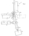
- a device designated as 1 for bending a hollow spacer profile 2 filled with desiccant has a tensioning device 3 lying in the feed direction of the profile 2 and a device 4 for detecting the leg 2 a of the profile 2 to be bent.
- the device 1 includes an abutment, in the exemplary embodiment an abutment mandrel 5, for fixing the inside of the curvature 6.
- the desiccant located in the interior of the hollow profile 2 can be partially displaced from this area of curvature from the outside of the bend 6 during the bending process and at the same time the profile outside can be stretched, elongated and rolled out.
- the bending area 6 of the profile 2 can be rolled several times, in particular with a high frequency, alternately in one and the other direction of its course during the bending process.
- the - profile outside 7 is rolled out like a piece of cake and thus receives a correspondingly larger dimension, which is desired on the outside of the bend 6, so that the desiccant located inside, which can only be partially displaced, does not blow this outside of the profile through the bend .
- the pressure roller 10 is arranged for this purpose at the end of a pivot lever 11 which can be driven for the back and forth movement according to the double arrow Pf 1 in the pivoting direction, in addition an effective in the direction of this pivot lever 11, to be described in more detail below, for pressing the pressure roller 10 is provided.
- This pressing device enables a certain advance of the pressure roller 10 in the direction of the pivoting lever 11 carrying it, so that an adaptation to this retraction especially with the ever increasing curvature - of the workpiece to be machined while maintaining the required contact pressure is possible.
- a profile area of approximately 2 cm in length or less, preferably approximately one cm in length, can be rolled.
- the profile area of the outside 7 of the curvature 6 is rolled, which begins in front of the actual apex 12 of the later finished bend 6 and extends approximately up to this apex 12 or preferably just behind it.
- material is repeatedly pushed and rolled into the area that should flow somewhat in the direction of profile 2 due to the bending movement according to arrow Pf 2.
- a working cylinder 13 acts transversely to the lever 11 on the latter outside of its pivot point 14.
- Such pneumatic or hydraulic working cylinders are known, which can be reversed at the desired high frequency in order to allow the rapid reciprocating movement of e.g. B. 10 to 40 z. B. 30 rolling movements per second.
- a second pivot lever 15 acts on the pivot lever 11, the pivot direction of which is oriented essentially in the direction of the first pivot lever 11 carrying the roller 10, which shapes the pivot bearing 14 of this first pivot lever 11 and on which an adjusting element 16, preferably attacks another pressure cylinder or the like.
- the two pivot levers 11 and 15 thus intersect and can be pivoted towards one another at their crossing point, namely the pivot bearing 14.
- the adjusting element 16 is a working and pressure cylinder and engages at one end of the second lever 15 while this second pivot lever 15 is in turn pivotally mounted about a point 17, which is opposite to the attack of this pressure cylinder 16 at the crossing point 14.
- the pressure cylinder 16 acts directly on the end of the pivot lever 11 opposite the roller 10, while the working cylinder 13 which generates the back and forth movement of the pivot lever 11 in turn pivots between the roller 10 and this pressure cylinder 16, for example approximately in the Middle attacks.
- the distances between the pivot bearing 17 and the attack of the adjusting element 16 are selected in the exemplary embodiment according to FIG. 1 for a pressure ratio of approximately 2: 1 in the sense of a ' pressure intensification. 1, a pressure translation can be achieved, while in the exemplary embodiment according to FIG. 2, such a pressure translation option is dispensed with in the interest of the simplest possible design.
- the mandrel-shaped abutment 5 has already been mentioned, around which the profile 2 can be bent.
- This abutment 5 can simultaneously form the inner end of a flap 18 which can be pivoted about its center 9 and which bears against the inside of the leg 2 a to be bent during the bending process and aligns and holds it together with the outer bending tool 4.
- a stop which overlaps the side surface of the profile 2 and which can prevent bulges in this area is provided in a manner not shown in detail. This stop can be moved at right angles to the side surface, after it has been bent to be able to release the process well.
- the clamping device In the direction of advance of the profile 2 in front of the bending point, the clamping device is provided, the movable clamping jaw 3 of which can be pressed from the outside against the side of the profile, the continuation of which forms the outside 7 of the bend 6 to be produced.
- a corresponding abutment 19 is provided on the inside. If necessary, the clamping jaw 3 can, in addition to its movement at right angles to the profile 2, perform a clamping movement against the base of the profile 2 and overlap the edge of the profile 2 in order to improve the fixation and alignment.
- an ejector 20 can be provided, the plunger 21 of which can engage the profile, preferably in the region of the inside of the curvature produced by the bending process, when the bending is complete and the rolling tool and the clamping jaw and bending tool are removed from the Profile area are sufficiently far away.
- the rolling frequency and / or the pressing force can be selected and adjusted so that different profile thicknesses, materials and. Like. Can be taken into account so that not only aluminum profiles, but also steel profiles can be bent in the manner according to the invention.
- an additional plastic deformation and elongation in this area is also possible during the bending process.
- the Outside 7 of the bend 6 are hammered at least during the bending process or kneaded or rolled by means of a sliding piece or mechanically placed under an appropriate pressure in some other way.
- a striking tool preferably a striking tool displaceable along the bending 6, or a press-on slide, kneading tool or the like could be provided as a tool for lengthening the outside 7 of the bend 6.
Landscapes
- Engineering & Computer Science (AREA)
- Mechanical Engineering (AREA)
- Civil Engineering (AREA)
- Structural Engineering (AREA)
- Bending Of Plates, Rods, And Pipes (AREA)
- Shaping Of Tube Ends By Bending Or Straightening (AREA)
Priority Applications (1)
| Application Number | Priority Date | Filing Date | Title |
|---|---|---|---|
| AT84103516T ATE32313T1 (de) | 1983-04-09 | 1984-03-30 | Verfahren und vorrichtung zum biegen von abstandhalter-profilen fuer isolierglasscheiben. |
Applications Claiming Priority (2)
| Application Number | Priority Date | Filing Date | Title |
|---|---|---|---|
| DE19833312764 DE3312764A1 (de) | 1983-04-09 | 1983-04-09 | Verfahren und vorrichtung zum biegen von abstandhalter-profilen fuer isolierglasscheiben |
| DE3312764 | 1983-04-09 |
Publications (3)
| Publication Number | Publication Date |
|---|---|
| EP0121873A2 true EP0121873A2 (fr) | 1984-10-17 |
| EP0121873A3 EP0121873A3 (en) | 1985-10-09 |
| EP0121873B1 EP0121873B1 (fr) | 1988-02-03 |
Family
ID=6195825
Family Applications (1)
| Application Number | Title | Priority Date | Filing Date |
|---|---|---|---|
| EP84103516A Expired EP0121873B1 (fr) | 1983-04-09 | 1984-03-30 | Procédé et dispositif de pliage de barres d'écartement pour vitres isolantes |
Country Status (3)
| Country | Link |
|---|---|
| EP (1) | EP0121873B1 (fr) |
| AT (1) | ATE32313T1 (fr) |
| DE (2) | DE3312764A1 (fr) |
Cited By (15)
| Publication number | Priority date | Publication date | Assignee | Title |
|---|---|---|---|---|
| FR2605915A1 (fr) * | 1986-11-03 | 1988-05-06 | Lisec Peter | Dispositif pour la formation d'un coin dans des tasseaux flexibles apposes sur une plaque de verre |
| WO1989007495A1 (fr) * | 1988-02-15 | 1989-08-24 | Claus Roulund | Procede servant a couder des pieces d'ecartement profilees pour vitre isolante, appareil de realisation dudit procede et piece d'ecartement profilee obtenue par ledit procede |
| EP0318748A3 (en) * | 1987-12-03 | 1990-06-13 | Franz Xaver Bayer Isolierglasfabrik Kg | Apparatus for bending a hollow profile, in particular a frame of spacekeeping profiles for insulating glass panes |
| US4947537A (en) * | 1988-06-30 | 1990-08-14 | Peter Lisec | Process and apparatus for filling hollow moldings |
| EP0459971A1 (fr) * | 1990-05-21 | 1991-12-04 | Peter Lisec | Procédé et dispositif pour obtenir des parties pliées dans les profilés d'écartement creux |
| EP0462961A1 (fr) * | 1990-05-21 | 1991-12-27 | Peter Lisec | Dispositif pour plier des profilés d'écartement creux |
| EP0483044A3 (en) * | 1990-10-26 | 1992-07-08 | Rolltech A/S | A bending machine |
| US5243844A (en) * | 1990-05-21 | 1993-09-14 | Peter Lisec | Process for producing curved sections in hollow profile strips |
| EP0894553A3 (fr) * | 1997-08-02 | 1999-08-25 | Franz Xaver Bayer Isolierglasfabrik Kg | Appareil pour plier un profil creux avec un élément de serrage |
| EP0983809A2 (fr) | 1998-08-29 | 2000-03-08 | Bayer Isolierglas- und Maschinentechnik GmbH | Méthode et dispositif pour le cintrage d' un profilé creux pour la fabrication d' un cadre intercalaire pour vitrage isolant |
| AT410909B (de) * | 2000-05-09 | 2003-08-25 | Lisec Peter | Verfahren und vorrichtung zum biegen von hohlprofilleisten zu abstandhalterrahmen für isolierglasscheiben |
| US6619098B2 (en) | 2001-08-28 | 2003-09-16 | Peter Lisec | Process and device for bending of hollow profile strips into spacer frames for insulating glass panes |
| EP1393831A3 (fr) * | 2002-08-02 | 2004-11-03 | Lenhardt Maschinenbau GmbH | Appareil pour plier des profils creux |
| CN102248041A (zh) * | 2010-05-17 | 2011-11-23 | 赵士平 | 中空玻璃铝隔条折弯机中的定位装置 |
| AT514109A1 (de) * | 2013-04-12 | 2014-10-15 | Progress Maschinen & Automation Ag | Biegemaschine |
Families Citing this family (7)
| Publication number | Priority date | Publication date | Assignee | Title |
|---|---|---|---|---|
| DE3523025A1 (de) * | 1985-06-27 | 1987-01-02 | Siemens Ag | Verfahren und vorrichtung zum biegen von langgestreckten metallischen werkstuecken |
| DE3740922A1 (de) * | 1987-12-03 | 1989-06-22 | Bayer Isolierglasfab Kg | Verfahren und vorrichtung zur herstellung eines abstandhalter-rahmens |
| DE3807529A1 (de) * | 1988-03-08 | 1989-09-21 | Bayer Isolierglasfab Kg | Verfahren und vorrichtung zum biegen von hohlen abstandhalterprofilen |
| DE3942809A1 (de) * | 1989-12-23 | 1991-06-27 | Bayer Isolierglasfab Kg | Verfahren und vorrichtung zum herstellen eines abstandhaltenden rahmens insbesondere fuer isolierglasscheiben |
| DE4225833C2 (de) * | 1992-08-05 | 1994-07-28 | Bayer Isolierglasfab Kg | Biegevorrichtung für Hohlprofile |
| DE19839735B4 (de) * | 1998-09-01 | 2005-03-03 | Franz Xaver Bayer Isolierglasfabrik Kg | Vorrichtung zum Biegen eines abstandhaltenden Innenrahmens für eine Isolierglasscheibe |
| DE19956046B4 (de) * | 1999-11-22 | 2004-12-30 | Bayer Isolierglas- Und Maschinentechnik Gmbh | Verfahren und Vorrichtung zur Herstellung eines Abstandhalterrahmens für Isolierglasscheiben |
Family Cites Families (9)
| Publication number | Priority date | Publication date | Assignee | Title |
|---|---|---|---|---|
| GB624169A (en) * | 1944-11-21 | 1949-05-30 | Sncase | Improvements in machines for bending angle and other metal rods, bars or the like |
| FR83512E (fr) * | 1962-12-05 | 1964-08-28 | Procédé et machine selon ce procédé pour cintrer les tubes d'un gros diamètre | |
| FR1479220A (fr) * | 1964-06-12 | 1967-05-05 | Machine à cintrer les tubes | |
| CH598878A5 (en) * | 1975-08-14 | 1978-05-12 | Stoecklin Walter Ag | Bending machine for ribbed circular sections |
| DE2714782A1 (de) * | 1977-04-02 | 1978-10-05 | Bertrams Ag | Verfahren und vorrichtung zur herstellung von rohrkruemmern |
| DE2829444C2 (de) * | 1978-07-05 | 1986-07-10 | Julius & August Erbslöh GmbH + Co, 5620 Velbert | Verfahren und Vorrichtung zur Herstellung eines Abstandhalterrahmens für Mehrscheiben-Isolierglas |
| CA1134125A (fr) * | 1978-06-14 | 1982-10-26 | Theo Janssens | Panneaux creux, et dispositif et methode de fabrication connexes |
| DE2924461C2 (de) * | 1979-06-18 | 1982-03-04 | Bertrams Ag, 5900 Siegen | Vorrichtung zur Herstellung von Rohrkrümmern |
| CH660398A5 (de) * | 1982-01-21 | 1987-04-15 | Peter Lisec | Abstandhalterrahmen fuer isolierglasscheiben sowie verfahren zur herstellung desselben und vorrichtung zur durchfuehrung des verfahrens. |
-
1983
- 1983-04-09 DE DE19833312764 patent/DE3312764A1/de not_active Withdrawn
-
1984
- 1984-03-30 AT AT84103516T patent/ATE32313T1/de not_active IP Right Cessation
- 1984-03-30 EP EP84103516A patent/EP0121873B1/fr not_active Expired
- 1984-03-30 DE DE8484103516T patent/DE3469138D1/de not_active Expired
Cited By (17)
| Publication number | Priority date | Publication date | Assignee | Title |
|---|---|---|---|---|
| FR2605915A1 (fr) * | 1986-11-03 | 1988-05-06 | Lisec Peter | Dispositif pour la formation d'un coin dans des tasseaux flexibles apposes sur une plaque de verre |
| EP0318748A3 (en) * | 1987-12-03 | 1990-06-13 | Franz Xaver Bayer Isolierglasfabrik Kg | Apparatus for bending a hollow profile, in particular a frame of spacekeeping profiles for insulating glass panes |
| WO1989007495A1 (fr) * | 1988-02-15 | 1989-08-24 | Claus Roulund | Procede servant a couder des pieces d'ecartement profilees pour vitre isolante, appareil de realisation dudit procede et piece d'ecartement profilee obtenue par ledit procede |
| US4947537A (en) * | 1988-06-30 | 1990-08-14 | Peter Lisec | Process and apparatus for filling hollow moldings |
| US5243844A (en) * | 1990-05-21 | 1993-09-14 | Peter Lisec | Process for producing curved sections in hollow profile strips |
| EP0462961A1 (fr) * | 1990-05-21 | 1991-12-27 | Peter Lisec | Dispositif pour plier des profilés d'écartement creux |
| US5117669A (en) * | 1990-05-21 | 1992-06-02 | Peter Lisec | Apparatus for bending hollow profile strips |
| EP0459971A1 (fr) * | 1990-05-21 | 1991-12-04 | Peter Lisec | Procédé et dispositif pour obtenir des parties pliées dans les profilés d'écartement creux |
| EP0483044A3 (en) * | 1990-10-26 | 1992-07-08 | Rolltech A/S | A bending machine |
| EP0894553A3 (fr) * | 1997-08-02 | 1999-08-25 | Franz Xaver Bayer Isolierglasfabrik Kg | Appareil pour plier un profil creux avec un élément de serrage |
| US6023956A (en) * | 1997-08-02 | 2000-02-15 | Franz Xaver Bayer Isolierglasfabrik Kg | Device for bending a hollow section with a hold down clamp |
| EP0983809A2 (fr) | 1998-08-29 | 2000-03-08 | Bayer Isolierglas- und Maschinentechnik GmbH | Méthode et dispositif pour le cintrage d' un profilé creux pour la fabrication d' un cadre intercalaire pour vitrage isolant |
| AT410909B (de) * | 2000-05-09 | 2003-08-25 | Lisec Peter | Verfahren und vorrichtung zum biegen von hohlprofilleisten zu abstandhalterrahmen für isolierglasscheiben |
| US6619098B2 (en) | 2001-08-28 | 2003-09-16 | Peter Lisec | Process and device for bending of hollow profile strips into spacer frames for insulating glass panes |
| EP1393831A3 (fr) * | 2002-08-02 | 2004-11-03 | Lenhardt Maschinenbau GmbH | Appareil pour plier des profils creux |
| CN102248041A (zh) * | 2010-05-17 | 2011-11-23 | 赵士平 | 中空玻璃铝隔条折弯机中的定位装置 |
| AT514109A1 (de) * | 2013-04-12 | 2014-10-15 | Progress Maschinen & Automation Ag | Biegemaschine |
Also Published As
| Publication number | Publication date |
|---|---|
| DE3469138D1 (en) | 1988-03-10 |
| ATE32313T1 (de) | 1988-02-15 |
| DE3312764A1 (de) | 1984-10-18 |
| EP0121873B1 (fr) | 1988-02-03 |
| EP0121873A3 (en) | 1985-10-09 |
Similar Documents
| Publication | Publication Date | Title |
|---|---|---|
| EP0121873A2 (fr) | Procédé et dispositif de pliage de barres d'écartement pour vitres isolantes | |
| DE3740921C2 (fr) | ||
| DE2948115A1 (de) | Verfahren und vorrichtung zum formen von eine naht aufweisenden rohren von bogenfoermigem querschnitt aus flaechigem material, insbesondere blech | |
| CH659962A5 (de) | Maschine zum herstellen eines abstandhaltenden innenrahmens fuer eine isolierglasscheibe. | |
| DE2642743C3 (de) | Vorrichtung zum Herstellen einer Kraftfahrzeug-Achse | |
| DE102014118368B3 (de) | Verfahren und Vorrichtung zum Herstellen einer Eckverbindung | |
| CH647167A5 (de) | Verfahren zur herstellung eines rohrbogens. | |
| DE2757886A1 (de) | Verfahren und vorrichtung zur herstellung von eckverbindungen von metallrahmen | |
| DE2930191A1 (de) | Vorrichtung zum formen und schliessen von faltschachteln | |
| DE19956046B4 (de) | Verfahren und Vorrichtung zur Herstellung eines Abstandhalterrahmens für Isolierglasscheiben | |
| DE2252920A1 (de) | Verfahren zum herstellen von hohlprofilen, vorrichtung zum ausfuehren des verfahrens und mit dem verfahren hergestelltes hohlprofil | |
| DE2015414A1 (en) | Joining hollow sections to form window frames etc | |
| DE2341857B1 (de) | Werkzeuganordnung zur Herstellung von Rohrboegen | |
| DE3231698A1 (de) | Verfahren zum formen der ecken von abstandhalterrahmen fuer isolierglas und vorrichtung zu seiner durchfuehrung | |
| DE3120897A1 (de) | "presse zum herstellen von holmen oder platten aus verleimten staeben" | |
| CH673604A5 (fr) | ||
| EP1281457B1 (fr) | Dispositif de cintrage des barres en profil creux | |
| DE3246988A1 (de) | Verfahren zum formen der ecken von abstandhalterrahmen fuer isolierglas und werkzeug zu seiner durchfuehrung | |
| DE1479275B2 (de) | Verfahren und Vorrichtung zum Abtren nen von Abfallstucken beim Herstellen von Hohlkörpern aus thermoplastischem Kunststoff im Blasverfahren | |
| DE102004060805A1 (de) | Verfahren und Vorrichtung zum Biegen von Hohlprofilstäben, insbesondere für Abstandhalterrahmen von Isolierglasscheiben | |
| DE1761372C3 (de) | Stanzwerkzeug | |
| EP0665357B1 (fr) | Procédé et dispositif pour la fabrication d'un cadre espaceur pour vitrages isolants | |
| DE102011051801B4 (de) | Verfahren und Vorrichtung zur Herstellung von Kernspangen und Kernspange | |
| DE4005095C2 (fr) | ||
| DE2342111C3 (de) | Verfahren und Vorrichtung zum Herstellen von Kanälen in Schaumstoff |
Legal Events
| Date | Code | Title | Description |
|---|---|---|---|
| PUAI | Public reference made under article 153(3) epc to a published international application that has entered the european phase |
Free format text: ORIGINAL CODE: 0009012 |
|
| AK | Designated contracting states |
Designated state(s): AT BE CH DE FR GB IT LI LU NL SE |
|
| PUAL | Search report despatched |
Free format text: ORIGINAL CODE: 0009013 |
|
| AK | Designated contracting states |
Designated state(s): AT BE CH DE FR GB IT LI LU NL SE |
|
| 17P | Request for examination filed |
Effective date: 19851017 |
|
| 17Q | First examination report despatched |
Effective date: 19860910 |
|
| ITF | It: translation for a ep patent filed | ||
| GRAA | (expected) grant |
Free format text: ORIGINAL CODE: 0009210 |
|
| AK | Designated contracting states |
Kind code of ref document: B1 Designated state(s): AT BE CH DE FR GB IT LI LU NL SE |
|
| REF | Corresponds to: |
Ref document number: 32313 Country of ref document: AT Date of ref document: 19880215 Kind code of ref document: T |
|
| REF | Corresponds to: |
Ref document number: 3469138 Country of ref document: DE Date of ref document: 19880310 |
|
| ET | Fr: translation filed | ||
| GBT | Gb: translation of ep patent filed (gb section 77(6)(a)/1977) | ||
| PG25 | Lapsed in a contracting state [announced via postgrant information from national office to epo] |
Ref country code: LU Free format text: LAPSE BECAUSE OF NON-PAYMENT OF DUE FEES Effective date: 19880331 |
|
| PLBE | No opposition filed within time limit |
Free format text: ORIGINAL CODE: 0009261 |
|
| STAA | Information on the status of an ep patent application or granted ep patent |
Free format text: STATUS: NO OPPOSITION FILED WITHIN TIME LIMIT |
|
| 26N | No opposition filed | ||
| PGFP | Annual fee paid to national office [announced via postgrant information from national office to epo] |
Ref country code: LU Payment date: 19900323 Year of fee payment: 7 |
|
| ITTA | It: last paid annual fee | ||
| EAL | Se: european patent in force in sweden |
Ref document number: 84103516.5 |
|
| PGFP | Annual fee paid to national office [announced via postgrant information from national office to epo] |
Ref country code: SE Payment date: 19990301 Year of fee payment: 16 |
|
| PGFP | Annual fee paid to national office [announced via postgrant information from national office to epo] |
Ref country code: BE Payment date: 19990308 Year of fee payment: 16 |
|
| PG25 | Lapsed in a contracting state [announced via postgrant information from national office to epo] |
Ref country code: SE Free format text: LAPSE BECAUSE OF NON-PAYMENT OF DUE FEES Effective date: 20000331 Ref country code: BE Free format text: LAPSE BECAUSE OF NON-PAYMENT OF DUE FEES Effective date: 20000331 |
|
| BERE | Be: lapsed |
Owner name: FRANZ XAVER BAYER ISOLIERGLASFABRIK K.G. Effective date: 20000331 |
|
| EUG | Se: european patent has lapsed |
Ref document number: 84103516.5 |
|
| PGFP | Annual fee paid to national office [announced via postgrant information from national office to epo] |
Ref country code: FR Payment date: 20010226 Year of fee payment: 18 |
|
| PGFP | Annual fee paid to national office [announced via postgrant information from national office to epo] |
Ref country code: NL Payment date: 20010331 Year of fee payment: 18 |
|
| REG | Reference to a national code |
Ref country code: GB Ref legal event code: IF02 |
|
| PGFP | Annual fee paid to national office [announced via postgrant information from national office to epo] |
Ref country code: GB Payment date: 20020829 Year of fee payment: 19 |
|
| PGFP | Annual fee paid to national office [announced via postgrant information from national office to epo] |
Ref country code: AT Payment date: 20020830 Year of fee payment: 19 |
|
| PGFP | Annual fee paid to national office [announced via postgrant information from national office to epo] |
Ref country code: CH Payment date: 20020920 Year of fee payment: 19 |
|
| PG25 | Lapsed in a contracting state [announced via postgrant information from national office to epo] |
Ref country code: NL Free format text: LAPSE BECAUSE OF NON-PAYMENT OF DUE FEES Effective date: 20021001 |
|
| PG25 | Lapsed in a contracting state [announced via postgrant information from national office to epo] |
Ref country code: FR Free format text: LAPSE BECAUSE OF NON-PAYMENT OF DUE FEES Effective date: 20021129 |
|
| NLV4 | Nl: lapsed or anulled due to non-payment of the annual fee |
Effective date: 20021001 |
|
| REG | Reference to a national code |
Ref country code: FR Ref legal event code: ST |
|
| PG25 | Lapsed in a contracting state [announced via postgrant information from national office to epo] |
Ref country code: GB Free format text: LAPSE BECAUSE OF NON-PAYMENT OF DUE FEES Effective date: 20030330 Ref country code: AT Free format text: LAPSE BECAUSE OF NON-PAYMENT OF DUE FEES Effective date: 20030330 |
|
| PG25 | Lapsed in a contracting state [announced via postgrant information from national office to epo] |
Ref country code: LI Free format text: LAPSE BECAUSE OF NON-PAYMENT OF DUE FEES Effective date: 20030331 Ref country code: CH Free format text: LAPSE BECAUSE OF NON-PAYMENT OF DUE FEES Effective date: 20030331 |
|
| PGFP | Annual fee paid to national office [announced via postgrant information from national office to epo] |
Ref country code: DE Payment date: 20030528 Year of fee payment: 20 |
|
| REG | Reference to a national code |
Ref country code: CH Ref legal event code: PL |
|
| GBPC | Gb: european patent ceased through non-payment of renewal fee |
Effective date: 20030330 |