EP0983860A2 - Grande Imprimante - Google Patents
Grande Imprimante Download PDFInfo
- Publication number
- EP0983860A2 EP0983860A2 EP99116782A EP99116782A EP0983860A2 EP 0983860 A2 EP0983860 A2 EP 0983860A2 EP 99116782 A EP99116782 A EP 99116782A EP 99116782 A EP99116782 A EP 99116782A EP 0983860 A2 EP0983860 A2 EP 0983860A2
- Authority
- EP
- European Patent Office
- Prior art keywords
- spindle
- paper
- printer
- set forth
- roll
- Prior art date
- Legal status (The legal status is an assumption and is not a legal conclusion. Google has not performed a legal analysis and makes no representation as to the accuracy of the status listed.)
- Granted
Links
- 238000000034 method Methods 0.000 claims abstract description 7
- 238000003780 insertion Methods 0.000 claims description 6
- 230000037431 insertion Effects 0.000 claims description 6
- 230000004308 accommodation Effects 0.000 claims description 4
- 238000005452 bending Methods 0.000 description 9
- 230000006866 deterioration Effects 0.000 description 2
- 238000009434 installation Methods 0.000 description 2
- 238000011144 upstream manufacturing Methods 0.000 description 2
- 239000004744 fabric Substances 0.000 description 1
Images



Classifications
-
- B—PERFORMING OPERATIONS; TRANSPORTING
- B41—PRINTING; LINING MACHINES; TYPEWRITERS; STAMPS
- B41J—TYPEWRITERS; SELECTIVE PRINTING MECHANISMS, i.e. MECHANISMS PRINTING OTHERWISE THAN FROM A FORME; CORRECTION OF TYPOGRAPHICAL ERRORS
- B41J11/00—Devices or arrangements of selective printing mechanisms, e.g. ink-jet printers or thermal printers, for supporting or handling copy material in sheet or web form
-
- B—PERFORMING OPERATIONS; TRANSPORTING
- B41—PRINTING; LINING MACHINES; TYPEWRITERS; STAMPS
- B41J—TYPEWRITERS; SELECTIVE PRINTING MECHANISMS, i.e. MECHANISMS PRINTING OTHERWISE THAN FROM A FORME; CORRECTION OF TYPOGRAPHICAL ERRORS
- B41J11/00—Devices or arrangements of selective printing mechanisms, e.g. ink-jet printers or thermal printers, for supporting or handling copy material in sheet or web form
- B41J11/001—Handling wide copy materials
-
- B—PERFORMING OPERATIONS; TRANSPORTING
- B41—PRINTING; LINING MACHINES; TYPEWRITERS; STAMPS
- B41J—TYPEWRITERS; SELECTIVE PRINTING MECHANISMS, i.e. MECHANISMS PRINTING OTHERWISE THAN FROM A FORME; CORRECTION OF TYPOGRAPHICAL ERRORS
- B41J15/00—Devices or arrangements of selective printing mechanisms, e.g. ink-jet printers or thermal printers, specially adapted for supporting or handling copy material in continuous form, e.g. webs
- B41J15/04—Supporting, feeding, or guiding devices; Mountings for web rolls or spindles
- B41J15/042—Supporting, feeding, or guiding devices; Mountings for web rolls or spindles for loading rolled-up continuous copy material into printers, e.g. for replacing a used-up paper roll; Point-of-sale printers with openable casings allowing access to the rolled-up continuous copy material
-
- B—PERFORMING OPERATIONS; TRANSPORTING
- B65—CONVEYING; PACKING; STORING; HANDLING THIN OR FILAMENTARY MATERIAL
- B65H—HANDLING THIN OR FILAMENTARY MATERIAL, e.g. SHEETS, WEBS, CABLES
- B65H16/00—Unwinding, paying-out webs
- B65H16/02—Supporting web roll
- B65H16/06—Supporting web roll both-ends type
-
- B—PERFORMING OPERATIONS; TRANSPORTING
- B65—CONVEYING; PACKING; STORING; HANDLING THIN OR FILAMENTARY MATERIAL
- B65H—HANDLING THIN OR FILAMENTARY MATERIAL, e.g. SHEETS, WEBS, CABLES
- B65H2301/00—Handling processes for sheets or webs
- B65H2301/40—Type of handling process
- B65H2301/41—Winding, unwinding
- B65H2301/413—Supporting web roll
- B65H2301/4136—Mounting arrangements not otherwise provided for
- B65H2301/41362—Mounting arrangements not otherwise provided for one of the supports for the roller axis being movable as auxiliary bearing
-
- B—PERFORMING OPERATIONS; TRANSPORTING
- B65—CONVEYING; PACKING; STORING; HANDLING THIN OR FILAMENTARY MATERIAL
- B65H—HANDLING THIN OR FILAMENTARY MATERIAL, e.g. SHEETS, WEBS, CABLES
- B65H2301/00—Handling processes for sheets or webs
- B65H2301/40—Type of handling process
- B65H2301/41—Winding, unwinding
- B65H2301/413—Supporting web roll
- B65H2301/4136—Mounting arrangements not otherwise provided for
- B65H2301/41366—Mounting arrangements not otherwise provided for arrangements for mounting and supporting and -preferably- driving the (un)winding shaft
-
- B—PERFORMING OPERATIONS; TRANSPORTING
- B65—CONVEYING; PACKING; STORING; HANDLING THIN OR FILAMENTARY MATERIAL
- B65H—HANDLING THIN OR FILAMENTARY MATERIAL, e.g. SHEETS, WEBS, CABLES
- B65H2801/00—Application field
- B65H2801/36—Plotting
Definitions
- the present invention relates to a large printer that employs roll paper, and in particular to a large printer that can print a large sheet of paper having a width of 420 mm or more.
- printer designs that provide for a paper roll to be located in the front of the printer main body, but since sheets are discharged to the front along U-shaped feeding paths, the path structures are complicated, and becomes more complicated when a plurality of paper rolls are set up for use.
- One printer though it is not a large printer that uses roll paper, is provided wherein, in order to reduce the installation space of the printer main body in the direction of depth, a paper feeding path in a subscanning direction, including a paper supply portion from which a sheet of paper is supplied and a paper ejection portion from which the sheet is ejected, is arranged so as to be substantially straight in the diagonal direction of a casing that constitutes a dark box.
- This printer is disclosed in Japanese Patent Publication No. 2-59372A.
- Paper rolls for large printers are correspondingly large, and quite heavy.
- no printer that uses such roll paper is considered or taught that permits a user to replace a heavy paper roll from the front of the printer while standing, and without bending at the waist.
- no printer which uses such roll paper is taught that can print also large sheets of stiff carton.
- a spindle on which a paper roll is mounted is held by a pair of spindle receptacles provided in the printer main body.
- a paper roll is exhausted, a new one is mounted in its place.
- the positions for the spindle receptacle pair are fixed, i.e., the spindle receptacles are located opposite each other, regardless of whether a spindle is mounted or not.
- a large printer comprising: a paper feeding unit in which at least one roll of paper and at least one sheet of paper including a stiff carton to be supplied are loaded, the paper feeding unit being located at a height that enables a user standing in front of the printer to execute the paper feeding process including replacement of the roll paper and setting the sheet of paper; a printing unit located below the paper feeding unit; a discharged paper stacking unit located below the printing unit; and a paper feeding path extending from the paper feeding unit to the discharged paper stacking unit via the printing unit so as to be substantially straight.
- the feeding unit in which roll paper is loaded is located at a height at which a user standing in front of the printer can replace a paper roll.
- a plurality of paper rolls are detachably loaded in the paper feeding unit such that the plural paper rolls are arranged obliquely with each other in the vertical direction. Accordingly, when one roll of paper is exhausted, it can be quickly replaced by a new paper roll. If the upper paper roll is used first, by switching from the upper to the lower paper roll a replacement for the upper paper roll can be loaded while the printing is continued.
- the paper feeding unit includes a cover member for covering the loaded paper roll from thereabove and for covering the paper roll and for supporting the supplied stiff carton from therebelow.
- a cover member for covering the loaded paper roll from thereabove and for covering the paper roll and for supporting the supplied stiff carton from therebelow.
- the feeding unit includes at least a pair of spindle receptacles into which both ends of an elongated spindle, on which a paper roll is mounted, are inserted. At least one of the spindle receptacles is rotatable, and one end of the spindle can be inserted into the rotatable spindle receptacle in order to insert the other end of the spindle into the other spindle receptacle by rotating the spindle so as to pivot on the rotatable spindle receptacle.
- the paper feeding path extends straightly from an upper rear portion of the printer to a lower front portion thereof.
- the paper feeding path may extend perpendicularly.
- a large printer using at least one roll of paper comprising: at least one pair of spindle receptacles into which both ends of an elongated spindle, on which a paper roll is mounted, are inserted. At least one of the spindle receptacles is rotatable, and one end of the spindle can be inserted into the rotatable spindle receptacle in order to insert the other end of the spindle into the other spindle receptacle by rotating the spindle so as to pivot on the rotatable spindle receptacle.
- the rotation of the rotatable spindle receptacle toward the front of the printer is limited to an angle ranging from 20 to 50 degrees.
- one end of a spindle can be inserted at an appropriate angle for which a large work space depth is not required. In this case, a range of from 30 to 40 degrees is more preferable.
- the rotatable spindle receptacle is so urged by urging means as to rotate automatically toward front of the printer for a rotation limit thereof when the spindle is removed.
- the rotatable spindle receptacle is automatically pivoted to the front at an appropriate angle.
- At least two pairs of the spindle receptacles are arranged obliquely with each other in the vertical direction. Therefore, when the paper in one roll is exhausted, it can be immediately replaced by the other one. If the upper paper roll is used first, the upper paper roll can be replaced by a new one while printing is continued by switching to the lower paper roll.
- a stopper is formed on one end of the spindle, and an engagement portion with which the stopper is engaged is formed in the rotatable spindle receptacle. Since the stopper engages the engagement portion when that end of the spindle is inserted into the spindle receptacle, the spindle will not be removed from the spindle receptacle by mistake during the replacement of a paper roll.
- the end of the spindle at which the stopper is formed differs in appearance from the other end for preventing the insertion of the wrong end of the spindle. Simply by glancing at the ends of the spindle a user can identify the end that is to be inserted first in addition to its original function.
- a large printer comprising: a sheet feeding area positioned at a height whereat a user standing in front of the printer is able to set up a printing medium.
- a plurality of paper rolls are loaded in the sheet feeding area so as to be arranged obliquely with each other in the vertical direction.
- the printing medium includes at least one roll of paper and at least one sheet of stiff carton.
- the sheet feeding area includes an accommodation space in which the paper roll is loaded and a cover member for covering the accommodation space from thereabove and for supporting the stiff carton from therebelow.
- the printer further comprises: an elongative member disposed in the paper feeding area for holding the printing medium; and a pair of support members for supporting both ends of the elongative member, at least one of the support members being rotatable.
- the printer further comprises: a printing area; a paper discharge area; and a paper feeding path extending from the paper feeding area to the paper discharge area via the printing area.
- the paper feeding area is located in an upper rear portion of the printer and the paper discharge area is located in a lower front portion of the printer.
- the paper feeding path may be extended from the paper feeding area to the paper discharge area via the printing area perpendicularly.
- a large printer for printing on paper supplied from a paper roll comprising: an elongative member for supporting the paper roll; and a pair of support members for supporting both ends of the elongative member, at least one of the supprt members being rotatable.
- the rotation of the rotatable support member toward the front of the printer is limited to an angle ranging from 20 to 50 degrees.
- the rotatable support member is so urged by urging means as to rotate automatically toward front of the printer for a rotation limit thereof when the spindle is removed.
- At least two pairs of the spindle receptacles are arranged obliquely with each other in the vertical direction.
- a stopper is formed on one end of the spindle, and an engagement portion with which the stopper is engaged is formed in the rotatable spindle receptacle.
- the end of the spindle at which the stopper is formed differs in appearance from the other end for preventing the insertion of the wrong end of the spindle.
- a large printer can print a large sheet of paper having a width of 420 mm or greater.
- the large printer includes a print head that can also print paper having a width less than 420 mm.
- a paper feeding unit can accept, as a printing medium, a paper roll having a width of about 210 mm to 1120 mm and a diameter of 10 cm to 15 cm, or a sheet of paper having approximately the same width as the roll paper, and a length of about 420 mm to 1580 mm (for paper having a thickness of less than 0.5 mm) or of about 420 mm to 730 mm (for stiff carton having a thickness of 0.5 mm to 1.5 mm).
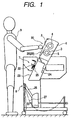
- a large printer comprises a paper feeding unit 30, a printing unit 7, and a discharged paper stacking unit 8, which are located at the top, middle and bottom positions, respectively.
- the external dimensions of the large printer are height: 1259 mm; width: 1688 mm; and width: 699 mm.
- the paper feeding path extending from the paper feeding unit 30 situated in upper rear portion of the main body to the discharged paper stacking unit 8 situated in lower front portion of the main body via the printing unit 7 is arranged so as to be substantially straight.
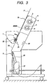
- the paper feeding unit 30 can feed both roll paper 3 and large sheets of stiff carton 21 (see Fig. 3). Specifically, paper rolls can be detachably loaded in the paper feeding unit 30 so that they it can be removed and replaced, and the stiff carton 21 can be mounted along the slope at the front face of the paper feeding unit 30, as is shown in Fig. 3.
- the force produced by suction is employed to draw the paper to the suction port 25 and to thereby control the delivery state, and the discharged paper stacking unit 8 is provided to accept printed paper.
- a stack cloth 27 is moved to the front of the printer by a discharged paper switch lever 26, and the printed matter is guided to the lower portion of the printer main body in the state depicted in Fig. 1.
- the stacking unit 8 is retracted by the lever 26 to a position whereat it does not prevent the discharge of the stiff carton 21.
- the paper feeding unit 30 is located at a height whereat a user 9 can perform a paper feeding process, including the replacement of paper rolls 3 and the setting up of stiff carton 21.
- the height of a user who is 170 mm tall is used to determine the height of the paper feeding unit 30. If the height of the paper feeding unit 30 can be adjusted, it can be set to provide an optimal height for an individual user.
- a paper feeding process such as the replacement of a paper roll 3, can be performed from the front of the large printer (the side whereat the user is located in Fig. 1).
- Fig. 2 is a schematic front view of the large printer according to the embodiment, and a paper roll cover 28 (described later) is not shown.
- a pair of spindle receptacles 1a and 1b and a second another pair of spindle receptacles 2a and 2b underneath are provided for the paper feeding unit 30 of the large printer.
- ends 4a and 4b of the spindle 4 are inserted into the spindle receptacles 1a and 1b, and ends 5a and 5b of the spindle 5 are inserted into the spindle receptacles 2a and 2b.
- the spindle receptacles 1a and 1b, and 2a and 2b are attached to the frame 6 of the printer main body.
- the two spindles 4 and 5 are positioned vertically at an oblique angle, so that relative to the user 9 the upper spindle 4 is at the rear.
- the paper roll 3 is so located that paper is delivered along the substantially straight paper feeding path that extends obliquely upward from the printing unit 7, and downward to the port for the discharged paper stacking unit 8.
- the stiff carton 21 can set up by mounting it on the slope at the front of the paper feeding unit 30.
- the paper roll cover 28 is provided in front of the loaded paper roll 3, i.e., in front of the area whereat the paper roll 3 is located, and serves as a supporting portion 29 when a sheet of the stiff carton 21 is set up.
- the paper roll cover 28 is opened or closed by rotating the free end thereof so as to pivot on the upper end thereof. When the paper roll cover 28 is closed, it can serve as a part of the paper feeding path used for printing a sheet of paper, such as a sheet of the stiff carton 21.
- the structures of the spindle receptacles 1a and 1b which are the essential components of the large printer of the present invention, will now be described while referring to Fig. 5. Since the other spindle receptacles 2a and 2b are the same as the spindle receptacles 1a and 1b, explanation for them will be omitted.
- the spindle receptacle 1a is formed so that it can be rotated along the horizontal plane.
- a rotary portion 11 is provided for a base 10 fixed to the frame 6 so that it can be pivoted on a support point 12.
- a pair of rollers 14, which are symmetrically positioned at the bottom of the recess 13 with the support point 12 in between, are provided to reduce the rotation load of the spindle 4.
- the rotation of the rotary portion 11 to the front of the printer is limited to an angle of from 20 to 50 degrees.
- the rotation is limited to a range of from 30 to 40 degrees, and in this embodiment, the rotation to the front of the printer is halted at an angle of approximately 35 degrees.
- the rotary portion 11 is provided with a spring (not shown) that rotates the rotary portion 11 to the front of the printer.
- the spring automatically positions the rotary portion 11 at an angle of about 35 degrees, the rotation limit
- an engagement portion 15 is provided at the rear of the recess 13, and as is shown in Fig. 6, a stopper 16 is provided at the end 4a of the spindle 4.
- the stopper 16 is formed like an annular flange, and the engagement portion 15 is shaped to fit the flanged stopper 16.
- the engagement portion 15 and the stopper 16 are not limited to the above described shapes.
- the structure of the other spindle receptacle 1b, into which the other end 4b of the spindle 4 is inserted, will now be described while referring to Fig. 5.
- the spindle receptacle 1b is fixed to the frame 6, and has a recess 17 into which the other end 4b of the spindle 4 is inserted.
- a pair of rollers 18 are provided at the bottom of the recess 17, which has a simple shape, and the cylindrical end 4b of the spindle 4 is inserted therein.
- the shape of the stopper 16 on the spindle 4 differs from the simple cylindrical shape of the other end, so that the difference in the shape can be recognized at a glance. Therefore, the flanged shape provides an identification function which prevents in advance the erroneous setup of the spindle 4.
- flanges 20 are used to hold the paper roll 3.
- the user 9 by checking the flange stopper 16, was able to identify which end of the spindle 4 should be inserted first. Then, as is shown in Fig. 4, with the spindle 4 supported by and pivoting on the spindle receptacle 1a, the user 9 inserts end 4b of the spindle 4 into the spindle receptacle 1b. An enlarged view of the final state is shown in Fig. 6.
- the paper feeding unit 30, wherein a paper roll 3 is set up is positioned at a height whereat the user 9, who is standing in front of the printer, can replace the paper roll 3 without having to bend at the waist.
- the user 9 does not have to move around to the back of the printer, and can easily and quickly perform the replacement process. Also, the user 9, again without bending at the waist, can easily set up a large sheet of stiff carton 21 on the printer.
- a plurality of paper rolls 3 are removably mounted in the paper feeding unit 30 at positions located obliquely upward and downward. With this arrangement, when one paper roll is exhausted, it can be quickly replaced by a new one. And if the upper paper roll is used first, by switching from the upper paper roll to the lower paper roll, printing can be continued while the upper paper roll is replaced.
- the end 4a of the spindle 4 is inserted into the rotatable spindle receptacle 1a, and then the spindle 4 is pivoted on the support point 12 of the rotatable spindle receptacle 1a so that the other end 4b of the spindle 4 can be inserted into the other spindle receptacle 1b.
- the paper feeding path in this embodiment is extended obliquely. However, it may be extended perpendicularly, and with this path also, while standing in front of the printer the user 9 can replace the heavy paper roll 3 without bending at the waist or moving around to the back of the printer. Further, the user 9, from the front of the printer, can easily load large sheets of the stiff carton 21 onto the paper feeding unit without bending at the waist.
- the rotation of the rotatable spindle receptacle 1a to the front of the large printer is limited to an angle ranging from 20 to 50 degrees, preferably one ranging from 30 to 40 degrees.
- the end 4a of the spindle 4 can be loaded from the front of the printer at an appropriate angle whereat a large work space depth is not required.
- the spindle receptacle 1a is automatically rotated to the front by a spring (not shown) and positioned at an appropriate angle.
- the direction of the spindle receptacle 1a need not be manually adjusted to facilitate the insertion of the end 4a of a spindle 4 when a new paper roll 3 is being loaded.
- the upper spindle Since two pairs of the spindle receptacles are provided, and are obliquely aligned vertically, the upper spindle being located to the rear, when the paper in one roll 3 is exhausted, it can immediately be replaced by the other one. And if the paper roll 3 on the upper spindle 4 is used first, by switching from the upper paper roll 4 to the lower paper roll 5, printing can continue while the upper paper roll is being replaced.
- the stopper 16 engages the engagement portion 15 when the end 4a of a spindle 4 is inserted into the spindle receptacle 1a, so that the spindle 4 will not be removed from the spindle receptacle 1a by mistake during the replacement of a paper roll 3.
- a user 9 can determine which end is to be inserted into the spindle receptacle 1a, the insertion of the incorrect end can be avoided.
Landscapes
- Unwinding Webs (AREA)
- Steroid Compounds (AREA)
Priority Applications (1)
| Application Number | Priority Date | Filing Date | Title |
|---|---|---|---|
| EP02008188A EP1225054B1 (fr) | 1998-08-31 | 1999-08-31 | Imprimante grande |
Applications Claiming Priority (4)
| Application Number | Priority Date | Filing Date | Title |
|---|---|---|---|
| JP24603998A JP3733245B2 (ja) | 1998-08-31 | 1998-08-31 | 大型プリンタ |
| JP24603998 | 1998-08-31 | ||
| JP24603598 | 1998-08-31 | ||
| JP10246035A JP2000072287A (ja) | 1998-08-31 | 1998-08-31 | 大型プリンタ |
Related Child Applications (1)
| Application Number | Title | Priority Date | Filing Date |
|---|---|---|---|
| EP02008188A Division EP1225054B1 (fr) | 1998-08-31 | 1999-08-31 | Imprimante grande |
Publications (3)
| Publication Number | Publication Date |
|---|---|
| EP0983860A2 true EP0983860A2 (fr) | 2000-03-08 |
| EP0983860A3 EP0983860A3 (fr) | 2001-05-02 |
| EP0983860B1 EP0983860B1 (fr) | 2002-11-27 |
Family
ID=26537533
Family Applications (2)
| Application Number | Title | Priority Date | Filing Date |
|---|---|---|---|
| EP99116782A Expired - Lifetime EP0983860B1 (fr) | 1998-08-31 | 1999-08-31 | Grande Imprimante |
| EP02008188A Expired - Lifetime EP1225054B1 (fr) | 1998-08-31 | 1999-08-31 | Imprimante grande |
Family Applications After (1)
| Application Number | Title | Priority Date | Filing Date |
|---|---|---|---|
| EP02008188A Expired - Lifetime EP1225054B1 (fr) | 1998-08-31 | 1999-08-31 | Imprimante grande |
Country Status (4)
| Country | Link |
|---|---|
| US (2) | US20010046405A1 (fr) |
| EP (2) | EP0983860B1 (fr) |
| AT (2) | ATE228437T1 (fr) |
| DE (2) | DE69904126T2 (fr) |
Cited By (1)
| Publication number | Priority date | Publication date | Assignee | Title |
|---|---|---|---|---|
| EP1288004A1 (fr) * | 2001-08-28 | 2003-03-05 | Xerox Corporation | Une enceinte étanche pour réguler les conditions d'environnement d'un support d'impression |
Families Citing this family (12)
| Publication number | Priority date | Publication date | Assignee | Title |
|---|---|---|---|---|
| US6817566B2 (en) * | 2002-10-30 | 2004-11-16 | Butler Automatic, Inc. | Web splicer |
| US7775732B2 (en) * | 2006-11-30 | 2010-08-17 | International Business Machines Corporation | Multi-roll paper supply for printer |
| US9254698B2 (en) * | 2007-01-26 | 2016-02-09 | Hewlett-Packard Development Company, L.P. | Printing apparatus |
| US20100200166A1 (en) * | 2009-02-10 | 2010-08-12 | Toshiba Tec Kabushiki Kaisha | Label printer |
| JP5631117B2 (ja) * | 2010-08-25 | 2014-11-26 | キヤノン株式会社 | 記録装置、検出方法、および検出装置 |
| US9002257B2 (en) * | 2011-08-01 | 2015-04-07 | Ricoh Company, Ltd. | Image forming apparatus |
| JP5949134B2 (ja) * | 2012-05-18 | 2016-07-06 | セイコーエプソン株式会社 | 記録装置 |
| US9931866B2 (en) * | 2014-08-19 | 2018-04-03 | Hewlett-Packard Development Company, L.P. | Media crash prevention surface to contact and guide media |
| DE102014225206B4 (de) * | 2014-12-09 | 2019-09-05 | Koenig & Bauer Ag | Rollen-Druckmaschine |
| JP6478035B2 (ja) * | 2015-03-20 | 2019-03-06 | セイコーエプソン株式会社 | 媒体支持ユニット、記録装置及び媒体支持方法 |
| JP6711780B2 (ja) * | 2017-05-12 | 2020-06-17 | キヤノン株式会社 | 記録装置 |
| JP2024024204A (ja) * | 2022-08-09 | 2024-02-22 | セイコーエプソン株式会社 | 印刷装置 |
Citations (1)
| Publication number | Priority date | Publication date | Assignee | Title |
|---|---|---|---|---|
| JPH0259372A (ja) | 1988-08-24 | 1990-02-28 | Canon Inc | 画像記録装置 |
Family Cites Families (25)
| Publication number | Priority date | Publication date | Assignee | Title |
|---|---|---|---|---|
| US731123A (en) * | 1901-11-14 | 1903-06-16 | Whitin Machine Works | Journal-bearing for the warp-beams of looms. |
| US810606A (en) * | 1903-10-26 | 1906-01-23 | Samuel Insull | Music-roll and adjustable driving-support therefor. |
| US938885A (en) | 1907-08-13 | 1909-11-02 | Arthur F Mcculley | Paper-roll attachment for type-writers. |
| US1128730A (en) | 1914-07-13 | 1915-02-16 | Greggar Smedal | Attachment for type-writers. |
| US2595055A (en) * | 1949-01-24 | 1952-04-29 | Curtis & Marble Machine Compan | Roll-handling and control mechanism for cloth inspecting machines |
| US3151551A (en) * | 1961-10-19 | 1964-10-06 | Orville V Dutro | Removable roller assembly for web processing apparatus |
| US4339093A (en) * | 1980-11-24 | 1982-07-13 | Shanklin Corporation | Pneumatic roll lifter |
| EP0391632B1 (fr) | 1989-04-03 | 1994-01-19 | Sharp Kabushiki Kaisha | Appareil d'avancement de feuilles pour appareil de fac-similé |
| US5042272A (en) * | 1990-07-12 | 1991-08-27 | Union Underwear Company Inc. | Knitting machine fabric roll doffing apparatus |
| JP3297431B2 (ja) | 1990-10-17 | 2002-07-02 | キヤノン株式会社 | 画像処理装置 |
| JPH0812493B2 (ja) | 1991-02-07 | 1996-02-07 | 松下電送株式会社 | 画像記録装置 |
| US5187532A (en) | 1991-11-04 | 1993-02-16 | Digital Magnetic Systems, Inc. | Electrostatic document copying system having sheet rolls supported by telescoping cantilevered arms |
| US5690774A (en) | 1991-12-19 | 1997-11-25 | Gordian Holding Corporation | Apparatus and method for maintaining the confidentiality of printed information |
| US5302037A (en) * | 1992-04-10 | 1994-04-12 | Hecon Corporation | Web handling and feeding system for printers |
| US5237378A (en) | 1992-05-26 | 1993-08-17 | Xerox Corporation | Copier/printer employing a roll media feed apparatus and dual functions sensors |
| US5374007A (en) * | 1993-01-22 | 1994-12-20 | Ncr Corporation | Ribbon supply apparatus |
| CA2145438C (fr) | 1995-03-24 | 1999-03-30 | Jvk Holdings Inc. | Dispositif pour le stockakge et le deroulement d'un revetement de sol, avec dispositif de nettoyage |
| US5838354A (en) | 1995-05-31 | 1998-11-17 | Olympus Optical Co., Ltd. | Image forming apparatus |
| DE69628093T2 (de) * | 1995-06-27 | 2004-04-01 | Fuji Photo Film Co., Ltd., Minami-Ashigara | Druckvorrichtung |
| US5653293A (en) * | 1995-10-30 | 1997-08-05 | Ellis; George E. | Portable wire puller |
| US5963216A (en) | 1996-04-25 | 1999-10-05 | Hewlett-Packard Company | Providing print preview of a print job using printing calls from a print driver |
| DE69705353T2 (de) * | 1996-04-29 | 2002-04-25 | Hewlett-Packard Co.(A Delaware Corporation), Palo Alto | Einstellbare Spindelantriebsanordnung für Medienförderung mittels Rollen in einem Tintenstrahldrucker/plotter |
| JPH1016329A (ja) * | 1996-07-02 | 1998-01-20 | Brother Ind Ltd | 画像形成装置 |
| JPH10202984A (ja) | 1997-01-28 | 1998-08-04 | Olympus Optical Co Ltd | プリントシート用コーティング装置 |
| US5911382A (en) | 1997-12-08 | 1999-06-15 | David M. Lee | Auxiliary printing media roll holder for printer/plotters |
-
1999
- 1999-08-30 US US09/386,000 patent/US20010046405A1/en not_active Abandoned
- 1999-08-31 DE DE69904126T patent/DE69904126T2/de not_active Expired - Lifetime
- 1999-08-31 AT AT99116782T patent/ATE228437T1/de not_active IP Right Cessation
- 1999-08-31 DE DE69926153T patent/DE69926153T2/de not_active Expired - Lifetime
- 1999-08-31 EP EP99116782A patent/EP0983860B1/fr not_active Expired - Lifetime
- 1999-08-31 AT AT02008188T patent/ATE299440T1/de not_active IP Right Cessation
- 1999-08-31 EP EP02008188A patent/EP1225054B1/fr not_active Expired - Lifetime
-
2001
- 2001-01-26 US US09/769,268 patent/US6595463B2/en not_active Expired - Lifetime
Patent Citations (1)
| Publication number | Priority date | Publication date | Assignee | Title |
|---|---|---|---|---|
| JPH0259372A (ja) | 1988-08-24 | 1990-02-28 | Canon Inc | 画像記録装置 |
Cited By (1)
| Publication number | Priority date | Publication date | Assignee | Title |
|---|---|---|---|---|
| EP1288004A1 (fr) * | 2001-08-28 | 2003-03-05 | Xerox Corporation | Une enceinte étanche pour réguler les conditions d'environnement d'un support d'impression |
Also Published As
| Publication number | Publication date |
|---|---|
| EP1225054A1 (fr) | 2002-07-24 |
| DE69926153T2 (de) | 2006-05-18 |
| DE69904126T2 (de) | 2003-07-31 |
| EP0983860A3 (fr) | 2001-05-02 |
| EP0983860B1 (fr) | 2002-11-27 |
| EP1225054B1 (fr) | 2005-07-13 |
| ATE228437T1 (de) | 2002-12-15 |
| US20010046405A1 (en) | 2001-11-29 |
| US6595463B2 (en) | 2003-07-22 |
| DE69926153D1 (de) | 2005-08-18 |
| US20010007227A1 (en) | 2001-07-12 |
| DE69904126D1 (de) | 2003-01-09 |
| ATE299440T1 (de) | 2005-07-15 |
Similar Documents
| Publication | Publication Date | Title |
|---|---|---|
| US6595463B2 (en) | Large printer | |
| JPS6138088B2 (fr) | ||
| EP0063590B1 (fr) | Insertion selective de papier et dispositif d'avancement pour une imprimante de feuilles individuelles | |
| US20050280202A1 (en) | Printer having media bin and method for operation | |
| US20040032481A1 (en) | Printer system for vertical or horizontal mounting | |
| US4469454A (en) | Print wheel mounting arrangement for print head and ribbon cartridge assembly | |
| EP0418740B1 (fr) | Appareil automatique d'alimentation de feuilles | |
| JP2002011917A (ja) | 情報端末用プリンタユニット | |
| EP0987115B1 (fr) | Imprimante avec deux positions de fonctionnement | |
| US5073055A (en) | Sheet-feed/sheet-receiving unit used in combination with printer | |
| JP3074051B2 (ja) | 封筒フィーダ装置 | |
| JP3733245B2 (ja) | 大型プリンタ | |
| JP3491256B2 (ja) | 大型プリンタ | |
| JP3606358B2 (ja) | 大型プリンタ | |
| GB2318348A (en) | Recording paper cassette | |
| EP0368280B1 (fr) | Appareil de formation d'images | |
| US8382091B2 (en) | Recording apparatus | |
| WO1982001514A1 (fr) | Insertion et avancement de papier commandes par un support de papier superieur | |
| JPH06179529A (ja) | 給紙装置及び給排紙台 | |
| JP2000071535A (ja) | 大型プリンタ | |
| JPH0725117Y2 (ja) | トイレットペーパストッカ | |
| JP2653917B2 (ja) | 給紙機能付スタッカ | |
| JP3808944B2 (ja) | 記録装置 | |
| JP2001171204A (ja) | プリンタの脚装置 | |
| JPH08282031A (ja) | 水平紙送り型プリンタ |
Legal Events
| Date | Code | Title | Description |
|---|---|---|---|
| PUAI | Public reference made under article 153(3) epc to a published international application that has entered the european phase |
Free format text: ORIGINAL CODE: 0009012 |
|
| AK | Designated contracting states |
Kind code of ref document: A2 Designated state(s): AT BE CH CY DE DK ES FI FR GB GR IE IT LI LU MC NL PT SE |
|
| AX | Request for extension of the european patent |
Free format text: AL;LT;LV;MK;RO;SI |
|
| PUAL | Search report despatched |
Free format text: ORIGINAL CODE: 0009013 |
|
| AK | Designated contracting states |
Kind code of ref document: A3 Designated state(s): AT BE CH CY DE DK ES FI FR GB GR IE IT LI LU MC NL PT SE |
|
| AX | Request for extension of the european patent |
Free format text: AL;LT;LV;MK;RO;SI |
|
| 17P | Request for examination filed |
Effective date: 20010705 |
|
| 17Q | First examination report despatched |
Effective date: 20010914 |
|
| AKX | Designation fees paid |
Free format text: AT BE CH CY DE DK ES FI FR GB GR IE IT LI LU MC NL PT SE |
|
| GRAG | Despatch of communication of intention to grant |
Free format text: ORIGINAL CODE: EPIDOS AGRA |
|
| GRAG | Despatch of communication of intention to grant |
Free format text: ORIGINAL CODE: EPIDOS AGRA |
|
| GRAH | Despatch of communication of intention to grant a patent |
Free format text: ORIGINAL CODE: EPIDOS IGRA |
|
| GRAH | Despatch of communication of intention to grant a patent |
Free format text: ORIGINAL CODE: EPIDOS IGRA |
|
| GRAA | (expected) grant |
Free format text: ORIGINAL CODE: 0009210 |
|
| AK | Designated contracting states |
Kind code of ref document: B1 Designated state(s): AT BE CH CY DE DK ES FI FR GB GR IE IT LI LU MC NL PT SE |
|
| PG25 | Lapsed in a contracting state [announced via postgrant information from national office to epo] |
Ref country code: NL Free format text: LAPSE BECAUSE OF FAILURE TO SUBMIT A TRANSLATION OF THE DESCRIPTION OR TO PAY THE FEE WITHIN THE PRESCRIBED TIME-LIMIT Effective date: 20021127 Ref country code: LI Free format text: LAPSE BECAUSE OF FAILURE TO SUBMIT A TRANSLATION OF THE DESCRIPTION OR TO PAY THE FEE WITHIN THE PRESCRIBED TIME-LIMIT Effective date: 20021127 Ref country code: IT Free format text: LAPSE BECAUSE OF FAILURE TO SUBMIT A TRANSLATION OF THE DESCRIPTION OR TO PAY THE FEE WITHIN THE PRESCRIBED TIME-LIMIT;WARNING: LAPSES OF ITALIAN PATENTS WITH EFFECTIVE DATE BEFORE 2007 MAY HAVE OCCURRED AT ANY TIME BEFORE 2007. THE CORRECT EFFECTIVE DATE MAY BE DIFFERENT FROM THE ONE RECORDED. Effective date: 20021127 Ref country code: GR Free format text: LAPSE BECAUSE OF FAILURE TO SUBMIT A TRANSLATION OF THE DESCRIPTION OR TO PAY THE FEE WITHIN THE PRESCRIBED TIME-LIMIT Effective date: 20021127 Ref country code: FI Free format text: LAPSE BECAUSE OF FAILURE TO SUBMIT A TRANSLATION OF THE DESCRIPTION OR TO PAY THE FEE WITHIN THE PRESCRIBED TIME-LIMIT Effective date: 20021127 Ref country code: CH Free format text: LAPSE BECAUSE OF FAILURE TO SUBMIT A TRANSLATION OF THE DESCRIPTION OR TO PAY THE FEE WITHIN THE PRESCRIBED TIME-LIMIT Effective date: 20021127 Ref country code: BE Free format text: LAPSE BECAUSE OF FAILURE TO SUBMIT A TRANSLATION OF THE DESCRIPTION OR TO PAY THE FEE WITHIN THE PRESCRIBED TIME-LIMIT Effective date: 20021127 Ref country code: AT Free format text: LAPSE BECAUSE OF FAILURE TO SUBMIT A TRANSLATION OF THE DESCRIPTION OR TO PAY THE FEE WITHIN THE PRESCRIBED TIME-LIMIT Effective date: 20021127 |
|
| REF | Corresponds to: |
Ref document number: 228437 Country of ref document: AT Date of ref document: 20021215 Kind code of ref document: T |
|
| REG | Reference to a national code |
Ref country code: GB Ref legal event code: FG4D |
|
| REG | Reference to a national code |
Ref country code: CH Ref legal event code: EP |
|
| REG | Reference to a national code |
Ref country code: IE Ref legal event code: FG4D |
|
| REF | Corresponds to: |
Ref document number: 69904126 Country of ref document: DE Date of ref document: 20030109 |
|
| PG25 | Lapsed in a contracting state [announced via postgrant information from national office to epo] |
Ref country code: SE Free format text: LAPSE BECAUSE OF FAILURE TO SUBMIT A TRANSLATION OF THE DESCRIPTION OR TO PAY THE FEE WITHIN THE PRESCRIBED TIME-LIMIT Effective date: 20030227 Ref country code: PT Free format text: LAPSE BECAUSE OF FAILURE TO SUBMIT A TRANSLATION OF THE DESCRIPTION OR TO PAY THE FEE WITHIN THE PRESCRIBED TIME-LIMIT Effective date: 20030227 Ref country code: DK Free format text: LAPSE BECAUSE OF FAILURE TO SUBMIT A TRANSLATION OF THE DESCRIPTION OR TO PAY THE FEE WITHIN THE PRESCRIBED TIME-LIMIT Effective date: 20030227 |
|
| NLV1 | Nl: lapsed or annulled due to failure to fulfill the requirements of art. 29p and 29m of the patents act | ||
| PG25 | Lapsed in a contracting state [announced via postgrant information from national office to epo] |
Ref country code: ES Free format text: LAPSE BECAUSE OF FAILURE TO SUBMIT A TRANSLATION OF THE DESCRIPTION OR TO PAY THE FEE WITHIN THE PRESCRIBED TIME-LIMIT Effective date: 20030529 |
|
| REG | Reference to a national code |
Ref country code: CH Ref legal event code: PL |
|
| ET | Fr: translation filed | ||
| PG25 | Lapsed in a contracting state [announced via postgrant information from national office to epo] |
Ref country code: MC Free format text: LAPSE BECAUSE OF NON-PAYMENT OF DUE FEES Effective date: 20030831 Ref country code: LU Free format text: LAPSE BECAUSE OF NON-PAYMENT OF DUE FEES Effective date: 20030831 Ref country code: CY Free format text: LAPSE BECAUSE OF FAILURE TO SUBMIT A TRANSLATION OF THE DESCRIPTION OR TO PAY THE FEE WITHIN THE PRESCRIBED TIME-LIMIT Effective date: 20030831 |
|
| PG25 | Lapsed in a contracting state [announced via postgrant information from national office to epo] |
Ref country code: IE Free format text: LAPSE BECAUSE OF NON-PAYMENT OF DUE FEES Effective date: 20030901 |
|
| PLBE | No opposition filed within time limit |
Free format text: ORIGINAL CODE: 0009261 |
|
| STAA | Information on the status of an ep patent application or granted ep patent |
Free format text: STATUS: NO OPPOSITION FILED WITHIN TIME LIMIT |
|
| 26N | No opposition filed |
Effective date: 20030828 |
|
| REG | Reference to a national code |
Ref country code: IE Ref legal event code: MM4A |
|
| REG | Reference to a national code |
Ref country code: FR Ref legal event code: PLFP Year of fee payment: 17 |
|
| PGFP | Annual fee paid to national office [announced via postgrant information from national office to epo] |
Ref country code: GB Payment date: 20150826 Year of fee payment: 17 Ref country code: DE Payment date: 20150825 Year of fee payment: 17 |
|
| PGFP | Annual fee paid to national office [announced via postgrant information from national office to epo] |
Ref country code: FR Payment date: 20150629 Year of fee payment: 17 |
|
| REG | Reference to a national code |
Ref country code: DE Ref legal event code: R119 Ref document number: 69904126 Country of ref document: DE |
|
| GBPC | Gb: european patent ceased through non-payment of renewal fee |
Effective date: 20160831 |
|
| REG | Reference to a national code |
Ref country code: FR Ref legal event code: ST Effective date: 20170428 |
|
| PG25 | Lapsed in a contracting state [announced via postgrant information from national office to epo] |
Ref country code: DE Free format text: LAPSE BECAUSE OF NON-PAYMENT OF DUE FEES Effective date: 20170301 Ref country code: FR Free format text: LAPSE BECAUSE OF NON-PAYMENT OF DUE FEES Effective date: 20160831 Ref country code: GB Free format text: LAPSE BECAUSE OF NON-PAYMENT OF DUE FEES Effective date: 20160831 |