EP0983951A2 - Dispositif correcteur à rouleaux ou à bande pour l'alignement latéral, en cours de faconnage, d'articles en feuilles ou en plaques partiellement pliés dans une plieuse-colleuse - Google Patents
Dispositif correcteur à rouleaux ou à bande pour l'alignement latéral, en cours de faconnage, d'articles en feuilles ou en plaques partiellement pliés dans une plieuse-colleuse Download PDFInfo
- Publication number
- EP0983951A2 EP0983951A2 EP99116454A EP99116454A EP0983951A2 EP 0983951 A2 EP0983951 A2 EP 0983951A2 EP 99116454 A EP99116454 A EP 99116454A EP 99116454 A EP99116454 A EP 99116454A EP 0983951 A2 EP0983951 A2 EP 0983951A2
- Authority
- EP
- European Patent Office
- Prior art keywords
- articles
- folder
- gluer
- folding
- rollers
- Prior art date
- Legal status (The legal status is an assumption and is not a legal conclusion. Google has not performed a legal analysis and makes no representation as to the accuracy of the status listed.)
- Granted
Links
- 238000004026 adhesive bonding Methods 0.000 title claims description 6
- 238000004519 manufacturing process Methods 0.000 claims description 18
- 238000011144 upstream manufacturing Methods 0.000 claims description 7
- 238000007493 shaping process Methods 0.000 claims description 5
- 239000011111 cardboard Substances 0.000 claims description 2
- 238000006073 displacement reaction Methods 0.000 claims description 2
- 238000004806 packaging method and process Methods 0.000 claims description 2
- 239000011087 paperboard Substances 0.000 claims 1
- 230000007246 mechanism Effects 0.000 description 5
- 125000006850 spacer group Chemical group 0.000 description 4
- 210000001364 upper extremity Anatomy 0.000 description 4
- 238000005520 cutting process Methods 0.000 description 3
- 230000008901 benefit Effects 0.000 description 2
- 241000287828 Gallus gallus Species 0.000 description 1
- 230000009471 action Effects 0.000 description 1
- 239000000969 carrier Substances 0.000 description 1
- 235000013330 chicken meat Nutrition 0.000 description 1
- 230000002860 competitive effect Effects 0.000 description 1
- 239000004020 conductor Substances 0.000 description 1
- 230000001419 dependent effect Effects 0.000 description 1
- 239000003292 glue Substances 0.000 description 1
- 238000005461 lubrication Methods 0.000 description 1
- 239000002184 metal Substances 0.000 description 1
- 238000000034 method Methods 0.000 description 1
- 238000003825 pressing Methods 0.000 description 1
- 230000000750 progressive effect Effects 0.000 description 1
- 230000001681 protective effect Effects 0.000 description 1
- 230000000284 resting effect Effects 0.000 description 1
- 230000007704 transition Effects 0.000 description 1
- 238000004804 winding Methods 0.000 description 1
Images



Classifications
-
- B—PERFORMING OPERATIONS; TRANSPORTING
- B65—CONVEYING; PACKING; STORING; HANDLING THIN OR FILAMENTARY MATERIAL
- B65H—HANDLING THIN OR FILAMENTARY MATERIAL, e.g. SHEETS, WEBS, CABLES
- B65H9/00—Registering, e.g. orientating, articles; Devices therefor
- B65H9/16—Inclined tape, roller, or like article-forwarding side registers
-
- B—PERFORMING OPERATIONS; TRANSPORTING
- B65—CONVEYING; PACKING; STORING; HANDLING THIN OR FILAMENTARY MATERIAL
- B65H—HANDLING THIN OR FILAMENTARY MATERIAL, e.g. SHEETS, WEBS, CABLES
- B65H9/00—Registering, e.g. orientating, articles; Devices therefor
- B65H9/16—Inclined tape, roller, or like article-forwarding side registers
- B65H9/166—Roller
-
- B—PERFORMING OPERATIONS; TRANSPORTING
- B65—CONVEYING; PACKING; STORING; HANDLING THIN OR FILAMENTARY MATERIAL
- B65H—HANDLING THIN OR FILAMENTARY MATERIAL, e.g. SHEETS, WEBS, CABLES
- B65H5/00—Feeding articles separated from piles; Feeding articles to machines
- B65H5/22—Feeding articles separated from piles; Feeding articles to machines by air-blast or suction device
-
- B—PERFORMING OPERATIONS; TRANSPORTING
- B31—MAKING ARTICLES OF PAPER, CARDBOARD OR MATERIAL WORKED IN A MANNER ANALOGOUS TO PAPER; WORKING PAPER, CARDBOARD OR MATERIAL WORKED IN A MANNER ANALOGOUS TO PAPER
- B31B—MAKING CONTAINERS OF PAPER, CARDBOARD OR MATERIAL WORKED IN A MANNER ANALOGOUS TO PAPER
- B31B2100/00—Rigid or semi-rigid containers made by folding single-piece sheets, blanks or webs
-
- B—PERFORMING OPERATIONS; TRANSPORTING
- B31—MAKING ARTICLES OF PAPER, CARDBOARD OR MATERIAL WORKED IN A MANNER ANALOGOUS TO PAPER; WORKING PAPER, CARDBOARD OR MATERIAL WORKED IN A MANNER ANALOGOUS TO PAPER
- B31B—MAKING CONTAINERS OF PAPER, CARDBOARD OR MATERIAL WORKED IN A MANNER ANALOGOUS TO PAPER
- B31B2100/00—Rigid or semi-rigid containers made by folding single-piece sheets, blanks or webs
- B31B2100/002—Rigid or semi-rigid containers made by folding single-piece sheets, blanks or webs characterised by the shape of the blank from which they are formed
- B31B2100/0024—Rigid or semi-rigid containers made by folding single-piece sheets, blanks or webs characterised by the shape of the blank from which they are formed having all side walls attached to the bottom
-
- B—PERFORMING OPERATIONS; TRANSPORTING
- B31—MAKING ARTICLES OF PAPER, CARDBOARD OR MATERIAL WORKED IN A MANNER ANALOGOUS TO PAPER; WORKING PAPER, CARDBOARD OR MATERIAL WORKED IN A MANNER ANALOGOUS TO PAPER
- B31B—MAKING CONTAINERS OF PAPER, CARDBOARD OR MATERIAL WORKED IN A MANNER ANALOGOUS TO PAPER
- B31B2120/00—Construction of rigid or semi-rigid containers
- B31B2120/30—Construction of rigid or semi-rigid containers collapsible; temporarily collapsed during manufacturing
-
- B—PERFORMING OPERATIONS; TRANSPORTING
- B31—MAKING ARTICLES OF PAPER, CARDBOARD OR MATERIAL WORKED IN A MANNER ANALOGOUS TO PAPER; WORKING PAPER, CARDBOARD OR MATERIAL WORKED IN A MANNER ANALOGOUS TO PAPER
- B31B—MAKING CONTAINERS OF PAPER, CARDBOARD OR MATERIAL WORKED IN A MANNER ANALOGOUS TO PAPER
- B31B50/00—Making rigid or semi-rigid containers, e.g. boxes or cartons
- B31B50/02—Feeding or positioning sheets, blanks or webs
- B31B50/04—Feeding sheets or blanks
- B31B50/044—Feeding sheets or blanks involving aligning
-
- B—PERFORMING OPERATIONS; TRANSPORTING
- B65—CONVEYING; PACKING; STORING; HANDLING THIN OR FILAMENTARY MATERIAL
- B65H—HANDLING THIN OR FILAMENTARY MATERIAL, e.g. SHEETS, WEBS, CABLES
- B65H2406/00—Means using fluid
- B65H2406/30—Suction means
- B65H2406/36—Means for producing, distributing or controlling suction
- B65H2406/366—Means for producing, distributing or controlling suction producing vacuum
- B65H2406/3662—Fans
Definitions
- the subject of the present invention is a device for correcting rollers or strip for lateral alignment, during shaping, of articles in sheets or sheets partially folded in a folder-gluer; machine commonly used in the packaging industry for making, for example, cardboard boxes from plate elements cut out.
- such machines generally consist at least of a feeder feeding the production of the boxes cut by cut from of a pile, of a breaker pre-crushing the 1st and 3rd folds at 180o then opening to again the cutting, of a module of folding machines with hooks which fold 180o the front legs then the rear legs of the cutout, of a gluing station, a folding machine with propellers and conical rollers for folding the 2nd and 4th folds of the cutting, of a presser which compresses the 2nd and 4th folds and deposits the boxes in tablecloth, and finally a receiving module which receives the boxes while now pressed to allow the glue to dry.
- the conveying of the cuts from one station to another is done at using belt conveyors which, by friction, grab the cut either between lower and upper belts, i.e. between belts lower and upper support rollers. It is common for such lower and upper conveyor devices are associated with means to orient the articles in a determined position at the entrance of the production line. In the case of folder-gluers, it is indeed each of the cutouts must be perfectly aligned according to one of its lateral sides in an orientation parallel to the direction of its conveying before undertaking any folding operation.
- this alignment lateral is made at the entrance of the machine, generally by the feeder which introduces the cutouts one by one on the belt conveyors in a position already perfectly aligned laterally, no device ensuring specifically this alignment is only planned along the path of the cutting in modules or stations located downstream of the feeder, where the scrolling items have already been partially shaped by the folder-gluer.
- the reason for this state is that in a production process such as previously described, the cut, once properly aligned, can be transformed into a box state without the folding or gluing operations disrupt its lateral alignment.
- the Swiss patent application No 1997 1274/97 proposes a roller conveyor device modifying the manufacturing method by pivoting, one by one in the horizontal plane scrolling elements of low specific mass.
- this invention once the front legs of the cutout were folded by the front hooks, it just repeat the same operation for the rear front legs after having took care to rotate the cutout on itself by half a turn in a horizontal plane.
- This alternative meets a double criterion aimed at improving production, on the one hand by halving the number of passages necessary for the realization of certain boxes with complicated folding, and on the other hand, by endeavoring to reduce the costs of manufacture of such machines.
- the present invention provides a corrective device for restoring alignment initial side of any article in sheet or plate partially folded and / or glued, having undergone a pivoting in the horizontal plane during shaping in a folder-gluer.
- the present invention relates to a corrector to rollers or strip of the aforementioned type and in accordance with what the claim 1.
- the use of a single lower conveyor in combination with an intangible support capable of pressing the cutout on the lower conveyor only allows get rid of any mechanical constraint within the cut between its different parts.
- the immaterial support means in question is given by a source creating depression or overpressure atmospheric, respectively below or above the scrolling article on the lower conveyor only.
- this new device corrector also guarantees, thanks to independent training of its lower carrier, maintaining a transition zone in which cuts can be decelerated to reduce the distance separating them. Indeed, given the rarely circular geometry of the cutouts shaped, it is necessary that the spacing between them has been more important in the area of their pivoting, within the previous module, that everywhere else in the production line. However, in order to optimize the subsequent rate of production of the boxes, it is of course advantageous to be able to find the initial spacing of the cutouts as it was before their introduction into the swivel module.
- the corrective device according to the invention also ensures that action by independent adjustment of his training speed. The scrolling articles will thus be able to undergo a deceleration during lateral realignment, without fear of any damage of their previously folded parts.
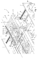
- Figure 1 provides a general view of the correction device 1 mounted between frames 2 (C.C.) and 3 (C.O.C.) of the folder-gluer, downstream of a pivot module 4 for turning the articles 8 in the plane horizontal in accordance with the new manufacturing method mentioned above.
- the direction of movement of the articles 8 scrolling above each of these devices 1 and 4 is given by the direction indicated by the arrow 5, and the axis 9 defined the initial virtual line against which said articles 8 fell previously supported in their upstream path before their rotation in the conveyor device 4.
- the device corrector 1 is based on a lower structure 6 transversely sliding, consisting of two rectangular cheeks 10 and 11, arranged vertically in their length on either side of the longitudinal axis 7 of the corrector 1.
- two crosspieces 12 and 13 are screwed, by their ends, to the cheeks 10 and 11 by pairs of screw 14.
- the along these, two longitudinal crosspieces 15 and 16 screwed by a plurality of screws 17 against the interior blanks of these cheeks.
- the upper part 26 of the device 1 mobile part in rotation in a horizontal plane around a pivot point 30.
- the structure forming the base of that upper part consists mainly of two side members 31 and 32 respectively placed on the driver side and on the side opposite driver. These beams are separated upstream by a plate 33 arranged horizontally and screwed into each of them by pairs of screw 34, and downstream by a spacer 35 screwed at its ends by screws 36 and crossed in its middle part by the pivot point 30.
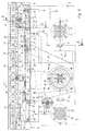
- the pivoting mechanism is actuated by the rotation of a steering wheel 46 disposed on the driver side upstream of the corrector device 1 on the upper part 26 ( Figure 2).
- This flywheel is pinned on a through screw 47 first of all a stop ring 48 arranged in the spar 31, then a stud threaded 49 constituting a support element which cannot deviate transversely of axis 7.
- this stud comprises at its base a axis 50 passing first through the plate 33 secured to the pivoting part upper 26, then the plate 41 rigidly fixed to the sliding part lower 6 ( Figure 4).
- the latter is pierced with a comfortable rectangular opening 51 of length equal to the maximum stroke which the upper part 26 can pivot the lower part 6 ( Figure 2). So that the screw 47 can induce movement of rotation of the upper part 26 while remaining integral with the latter, it is necessary that the threaded stud 49 can, through its axis 50, to both turn on itself and move across the plate 41 in a longitudinal movement along the axis 7 of the correction device. To do this, the axis 50 is held in its vertical plane by a circlip 52 while being able to move longitudinally through an oblong opening 53 formed in the plate 41 along the axis 7.
- Locking the upper part 26 in an oblique position axis 55 is illustrated in Figure 5 and obtained by tightening two brackets 60 and 61 between them, one secured to the upper part and the other to the part of the corrective device.
- the upper bracket 60 is screwed into the spar 31 by two screws 62, and the lower bracket 61 is made secured to the cheek 10 by two screws 63.
- the conveying of the scrolling articles 8 is ensured by a plurality of rollers 70 aligned side by side and resting at their ends in ball bearings 71 and 72 housed in the upper part of the side members 31 and 32.
- a screw 73 makes it possible to fix the corresponding span of the roller 70 in the bore of the bearing 71 as shown in Figure 4.
- each bearing 72 is held axially from each of its sides by a stop plate 74 screwed to the side member 32 by a plurality of screws 75.
- a screw 76 maintains a pulley 77 on the bearing surface each roller 70.
- Two bent protective sheets 78 and 79 are fixed on along each spar 31 and 32 and constitute a security guard against the exposed side portions of the rollers.
- Figure 3 makes it possible to follow, in phantom, the winding course a belt 80 running around the pulleys 77, and around a plurality of return pulleys 82. Each of these is fixed to the side member 32, opposite driver side, by a screw 83 passing through its ball bearing 84.
- the entire roller drive device 70 is located on the side opposite conductor outside the cheek 11 and the side member 32.
- the belt 80 is set in motion by the rotation of a drive pulley 85 of large diameter, mounted on at least one ball bearing 86 itself crossed by a hexagon drive axle 87. The latter is maintained in its ends by ball bearings, housed against the frames 2 and 3 of the folder-gluer, and driven in its C.O.C.
- an extendable protection 90 fixed against the faces interior of frames 2 and 3, covers the drive axis 87 in both areas outside the cheeks 10 and 11.
- a second protection 91 consisting of a trapezoidal sheet held against the cheek 11 by spacers 92, completely hides the belt drive 80 and This prevents any dangerous access to the moving part ( Figures 1 and 5).
- the belt 80 passes through a tension pulley 93 adjustable in position in the horizontal plane using an adjustment screw 94. This tensioning pulley can freely slide along the beam 32 in a groove 95 to bear, by tensioning the belt, against the screw setting 94.
- the latter is supported by a tapped stud 96 fixed by two screws against the outer face of the beam 32.
- FIGS. 1 and 4 show a longitudinal guide rail 100, welded against the lateral edges of two metal tabs 101 each pierced with a oblong opening 102 which precisely allows this rail to be positioned different distances from the frame 2, in an orientation parallel to the axis 7 of the folder-gluer.
- the inner edge of this rail should merge with axis 9 materializing the virtual line against which the line must be aligned corresponding edge of each of the articles leaving the correcting device.
- Two knobs 103 ensure the tightening of the guide rail after have it positioned correctly by means of two strips graduated by example.
- Each of the knobs 103 is screwed, on the driver's side or the other, in a support 104 fixed on a spacer 105 by two screws 106.
- the spacer 105 is fixed by two screws 107 on the crosspiece 15 or 16 respectively through the cheek 10 or 11.
- a fan 110 centered on axis 55, is placed just below the rollers 70 so as to create a tacky suction source the scrolling elements 8 against the upper surface of the rollers.
- suction source 110 is fixed under a perforated sheet 111, bent upward at its ends, and occupying all the available space between the beams 31 and 32.
- Brackets 112 and fixing screws 113 hold the perforated sheet against the faces interior of the side members 31 and 32.
- a second sheet 114 perforated and retractable, is placed above the scrolling articles on the rollers 70, and makes it possible to avoid the natural raising of their parts previously folded.
Landscapes
- Engineering & Computer Science (AREA)
- Mechanical Engineering (AREA)
- Making Paper Articles (AREA)
- Folding Of Thin Sheet-Like Materials, Special Discharging Devices, And Others (AREA)
- Registering Or Overturning Sheets (AREA)
- Separation, Sorting, Adjustment, Or Bending Of Sheets To Be Conveyed (AREA)
Abstract
Description
- la figure 1 représente une vue en perspective de dos du dispositif correcteur placé entre les bâtis de la plieuse-colleuse, en aval d'un module de pivotement permettant d'appliquer, à l'article défilant, une rotation dans le plan horizontal,
- la figure 2 montre, dans une vue en plan, le dispositif correcteur placé entre les deux bâtis de la plieuse-colleuse, dans une position oblique tournée dans le plan horizontal,
- la figure 3 montre le dispositif correcteur selon l'invention dans une vue de face représentée d'aprés une coupe médiane longitudinale,
- les figures 4, 5 et 6 représentent le dispositif correcteur dans des vues en coupes transversales simplifiées, respectivement selon les lignes A-A, B-B et C-C de la figure 3.
Claims (5)
- Dispositif correcteur (1) à rouleaux ou à bande pour l'alignement latéral, en cours de façonnage, d'articles (8) en feuilles ou en plaques partiellement pliés dans une plieuse-colleuse, caractérisé en ce que le dispositif est constitué d'une structure inférieure (6) au-dessus de laquelle est montée en pivotement dans le plan horizontal une structure supérieure (26) comportant une rangée d'éléments transporteurs (70), en contact avec la surface plane inférieure des articles (8) et entraínés par un moyen distinct (87) à vitesse réglable, en ce que le moyen correcteur est constitué d'un élément de guidage (100) déplaçable parallèlement à un axe (9) matérialisant la ligne virtuelle initiale contre laquelle lesdits articles (8) se sont précédemment appuyés dans leur cheminement amont, avant une opération de rotation effectuée dans un dispositif transporteur (4), et en ce qu'un moyen (110) permet d'appliquer à ces articles, en direction desdits éléments transporteurs (70) constituant une surface perméable à l'air, une pression choisie pour que, ajoutée à la masse spécifique de ces articles, la force de frottement résultante entre les éléments transporteurs (70) et ces articles soit apte à transmettre à chacun d'entre eux une vitesse sensiblement égale à celle des éléments transporteurs quelle que soit la masse spécifique de ces articles.
- Dispositif selon la revendication 1, caractérisé en ce que la structure inférieure (6) peut se déplacer, perpendiculairement par rapport à l'axe de défilement (7) des articles dans la plieuse-colleuse, grâce au coulissement de deux paires de paliers (20, 21) sur deux moyens de guidage (18, 19) situé entre deux bâtis (2, 3) de la plieuse-colleuse intégrant l'objet de la présente invention, et en ce que l'entraínement de ce déplacement peut être manuel ou automatisé.
- Dispositif selon la revendication 1, caractérisé en ce que la structure supérieure (26) est portée par la structure inférieure (6) d'une part grâce à une plaque (41), à faible coefficient de frottement, solidaire de cette dernière et sur laquelle glisse une partie de la structure supérieure (26), et d'autre part grâce à un point de pivot (30) seul mobile en rotation, situé sur l'axe de défilement (7), et rendu solidaire de la partie inférieure (6), en ce que la structure supérieure (26) peut être pivotée dans le plan horizontal par rapport à la structure inférieure (6), dans un sens ou dans l'autre autour du point de pivot (30), au moyen d'un actuateur (47) solidaire de la partie supérieure (26) et disposé à proximité de l'une de ses extrémités.
- Utilisation du dispositif correcteur (1) selon l'une des revendications précédentes dans une ligne de production pour la fabrication d'articles d'emballage (8) obtenus notamment par pliage et collage à partir de découpes de papier ou de carton, après que ces dernières aient été au moins partiellement façonnées par une telle dite ligne de production.
- Utilisation selon la revendication 4, caractérisée en ce que des moyens de maintien (114) des parties pliées desdits articles (8) s'étendent parallèlement au-dessus du dispositif correcteur (1), et en ce que ces moyens de maintien sont escamotables et constituent une surface lisse perméable à l'air, n'entravant pas la course desdites parties pliées.
Applications Claiming Priority (2)
| Application Number | Priority Date | Filing Date | Title |
|---|---|---|---|
| CH178998 | 1998-09-02 | ||
| CH01789/98A CH693177A5 (fr) | 1998-09-02 | 1998-09-02 | Dispositif correcteur à rouleaux ou à bande pour l'alignement latéral, en cours de façonnage, d'articles en feuilles ou en plaques partiellement pliés dans une plieuse-colleuse. |
Publications (3)
| Publication Number | Publication Date |
|---|---|
| EP0983951A2 true EP0983951A2 (fr) | 2000-03-08 |
| EP0983951A3 EP0983951A3 (fr) | 2000-06-07 |
| EP0983951B1 EP0983951B1 (fr) | 2003-03-12 |
Family
ID=4218642
Family Applications (1)
| Application Number | Title | Priority Date | Filing Date |
|---|---|---|---|
| EP99116454A Expired - Lifetime EP0983951B1 (fr) | 1998-09-02 | 1999-08-21 | Dispositif correcteur à rouleaux ou à bande pour l'alignement latéral, en cours de faconnage, d'articles en feuilles ou en plaques partiellement pliés dans une plieuse-colleuse |
Country Status (13)
| Country | Link |
|---|---|
| US (1) | US6162157A (fr) |
| EP (1) | EP0983951B1 (fr) |
| JP (1) | JP3497782B2 (fr) |
| KR (1) | KR100350918B1 (fr) |
| CN (1) | CN1128742C (fr) |
| AT (1) | ATE234252T1 (fr) |
| BR (1) | BR9903993A (fr) |
| CA (1) | CA2280075C (fr) |
| CH (1) | CH693177A5 (fr) |
| DE (1) | DE69905820T2 (fr) |
| DK (1) | DK0983951T3 (fr) |
| ES (1) | ES2193637T3 (fr) |
| TW (1) | TW438703B (fr) |
Cited By (2)
| Publication number | Priority date | Publication date | Assignee | Title |
|---|---|---|---|---|
| CN103431514A (zh) * | 2013-09-02 | 2013-12-11 | 陕西理工机电科技有限公司 | 干法造纸法再造烟叶薄片整装生产线 |
| CN109095225A (zh) * | 2018-09-09 | 2018-12-28 | 浙江美诺地毯制造有限公司 | 一种毛毯生产用传送带 |
Families Citing this family (17)
| Publication number | Priority date | Publication date | Assignee | Title |
|---|---|---|---|---|
| US7601218B2 (en) * | 2002-12-05 | 2009-10-13 | Valco Cincinnati, Inc. | Auto-tracking dispenser |
| US6851633B2 (en) * | 2002-12-05 | 2005-02-08 | Valco Cincinnati, Inc. | Auto-tracking dispenser |
| US20050045271A1 (en) * | 2003-08-30 | 2005-03-03 | Hunter Robert J. | Method of producing reinforced cartons |
| US20060000544A1 (en) * | 2004-01-09 | 2006-01-05 | Riverwood International Corporation | Method of producing cartons |
| TWI249467B (en) * | 2004-04-21 | 2006-02-21 | Bobst Sa | Device for aligning plate-like workpieces in a machine processing them |
| ATE350320T1 (de) * | 2004-04-21 | 2007-01-15 | Bobst Sa | Vorrichtung zum ausrichten von plattenförmigen elementen in einer maschine zu ihrer bearbeitung |
| US7398874B2 (en) * | 2005-01-07 | 2008-07-15 | Tgw-Ermanco, Inc. | Belt-driven accumulator for curved roller segment |
| DE102005019068A1 (de) * | 2005-04-23 | 2007-03-29 | Knapp Logistik Automation Ges.M.B.H. | Fördereinrichtung mit Richtungswechsel zum Fördern von Stückgut |
| US20070163720A1 (en) * | 2005-12-08 | 2007-07-19 | Tsair Shuenn Machinery Ind., Co., Ltd. | Top press plate of aluminum extrude and its clamp assembly for folder gluer |
| DE102007026194B4 (de) | 2007-06-04 | 2018-07-12 | Atlantic Zeiser Gmbh | Vorrichtung zum Bearbeiten flächiger Teile und Verfahren |
| WO2010102783A1 (fr) * | 2009-03-13 | 2010-09-16 | Bobst Sa | Dispositif de transfert pour support plan dans une machine de production d'emballages |
| JP5445863B2 (ja) * | 2010-08-04 | 2014-03-19 | 株式会社ダイフク | 板状体搬送装置 |
| DE102011008590A1 (de) * | 2011-01-14 | 2012-07-19 | Heidelberger Druckmaschinen Ag | Vorrichtung zum Ausrichten flacher Gegenstände, insbesondere von Faltschachtelzuschnitten |
| US8763789B2 (en) | 2012-03-08 | 2014-07-01 | Tgw Systems, Inc. | Drive system for curved roller conveyor segments |
| US8915497B2 (en) | 2013-01-04 | 2014-12-23 | Tamarack Products, Inc. | Method and apparatus for sheet and carton blank aligning using caster effect |
| IT202000016717A1 (it) * | 2020-07-09 | 2022-01-09 | Gd Spa | Unita' di alimentazione di sbozzati per una macchina impacchettatrice e provvista di un elemento di riferimento di posizione |
| CN112938558B (zh) * | 2021-01-29 | 2023-04-07 | 贵阳天海数码科技有限公司 | 基于扫描的图像自动纠正系统 |
Citations (1)
| Publication number | Priority date | Publication date | Assignee | Title |
|---|---|---|---|---|
| CH127497A (de) | 1926-03-13 | 1928-09-01 | Emil Gminder | Einrichtung zum Mustern vegetabilischen Textilgutes im Quellungsverfahren. |
Family Cites Families (10)
| Publication number | Priority date | Publication date | Assignee | Title |
|---|---|---|---|---|
| CH423446A (fr) | 1965-08-31 | 1966-10-31 | Bobst Fils Sa J | Mécanisme transporteur dans une machine pliant des découpes, par exemple de carton |
| US3439793A (en) * | 1967-07-19 | 1969-04-22 | Robert H Rakestraw | Conveying and orientation apparatus particularly for tobacco leaves |
| US3690222A (en) * | 1970-07-10 | 1972-09-12 | Paul H Schroeder | Device for closing and securing carton flaps |
| US4387890A (en) * | 1980-07-14 | 1983-06-14 | E.C.H. Will (Gmbh & Co.) | Apparatus for changing the orientation of stacked paper sheets or the like |
| US4930764A (en) * | 1988-12-28 | 1990-06-05 | Pitney Bowes Inc. | Front end feeder for mail handling machine |
| US5582087A (en) * | 1990-06-11 | 1996-12-10 | Roll Systems, Inc. | High speed sheet feeder |
| US5400706A (en) * | 1993-09-21 | 1995-03-28 | Signode Corporation | Machine for strapping load-carrying skid |
| US5601283A (en) * | 1996-01-11 | 1997-02-11 | Xerox Corporation | Cross roll registration deskew based on paper weight |
| US5697609A (en) * | 1996-06-26 | 1997-12-16 | Xerox Corporation | Lateral sheet pre-registration device |
| US5960933A (en) * | 1997-06-23 | 1999-10-05 | Tetra Laval Holdings & Finance, Sa | Conveyor belt for non-slip material handling |
-
1998
- 1998-09-02 CH CH01789/98A patent/CH693177A5/fr not_active IP Right Cessation
-
1999
- 1999-07-20 TW TW088112287A patent/TW438703B/zh not_active IP Right Cessation
- 1999-08-05 CN CN99111320A patent/CN1128742C/zh not_active Expired - Fee Related
- 1999-08-11 CA CA002280075A patent/CA2280075C/fr not_active Expired - Fee Related
- 1999-08-21 DE DE69905820T patent/DE69905820T2/de not_active Expired - Fee Related
- 1999-08-21 ES ES99116454T patent/ES2193637T3/es not_active Expired - Lifetime
- 1999-08-21 EP EP99116454A patent/EP0983951B1/fr not_active Expired - Lifetime
- 1999-08-21 DK DK99116454T patent/DK0983951T3/da active
- 1999-08-21 AT AT99116454T patent/ATE234252T1/de not_active IP Right Cessation
- 1999-08-30 KR KR1019990036269A patent/KR100350918B1/ko not_active Expired - Fee Related
- 1999-09-01 US US09/388,815 patent/US6162157A/en not_active Expired - Fee Related
- 1999-09-01 BR BR9903993-1A patent/BR9903993A/pt not_active IP Right Cessation
- 1999-09-02 JP JP24930199A patent/JP3497782B2/ja not_active Expired - Fee Related
Patent Citations (1)
| Publication number | Priority date | Publication date | Assignee | Title |
|---|---|---|---|---|
| CH127497A (de) | 1926-03-13 | 1928-09-01 | Emil Gminder | Einrichtung zum Mustern vegetabilischen Textilgutes im Quellungsverfahren. |
Cited By (3)
| Publication number | Priority date | Publication date | Assignee | Title |
|---|---|---|---|---|
| CN103431514A (zh) * | 2013-09-02 | 2013-12-11 | 陕西理工机电科技有限公司 | 干法造纸法再造烟叶薄片整装生产线 |
| CN103431514B (zh) * | 2013-09-02 | 2015-02-18 | 陕西理工机电科技有限公司 | 干法造纸法再造烟叶薄片整装生产线 |
| CN109095225A (zh) * | 2018-09-09 | 2018-12-28 | 浙江美诺地毯制造有限公司 | 一种毛毯生产用传送带 |
Also Published As
| Publication number | Publication date |
|---|---|
| JP3497782B2 (ja) | 2004-02-16 |
| DK0983951T3 (da) | 2003-07-14 |
| ES2193637T3 (es) | 2003-11-01 |
| BR9903993A (pt) | 2000-09-05 |
| EP0983951A3 (fr) | 2000-06-07 |
| TW438703B (en) | 2001-06-07 |
| DE69905820D1 (de) | 2003-04-17 |
| CA2280075C (fr) | 2002-03-12 |
| KR20000022790A (ko) | 2000-04-25 |
| EP0983951B1 (fr) | 2003-03-12 |
| CH693177A5 (fr) | 2003-03-27 |
| US6162157A (en) | 2000-12-19 |
| DE69905820T2 (de) | 2003-12-11 |
| CN1246429A (zh) | 2000-03-08 |
| JP2000102995A (ja) | 2000-04-11 |
| KR100350918B1 (ko) | 2002-08-28 |
| ATE234252T1 (de) | 2003-03-15 |
| CA2280075A1 (fr) | 2000-03-02 |
| CN1128742C (zh) | 2003-11-26 |
Similar Documents
| Publication | Publication Date | Title |
|---|---|---|
| EP0983951B1 (fr) | Dispositif correcteur à rouleaux ou à bande pour l'alignement latéral, en cours de faconnage, d'articles en feuilles ou en plaques partiellement pliés dans une plieuse-colleuse | |
| EP3038954B1 (fr) | Procédé pour transporter et tourner des objets plats | |
| EP0411981B1 (fr) | Procédé et machine de banderolage d'une charge palettisée | |
| EP2337677B1 (fr) | Dispositif de transport et de pliage de decoupes | |
| EP0248700B1 (fr) | Machine d'encaissage pour caisses américaines | |
| FR2679818A1 (fr) | Procede et dispositif pour la decoupe de plaques de verre plat. | |
| EP0881173A1 (fr) | Transporteur à rouleaux ou à bande pour transporter et tourner des articles an feuilles ou en plaques de faible masse spécifique | |
| EP1369213B1 (fr) | Dispositif pour rompre des points d'attache reliant des feuilles de carton empilées | |
| FR2715911A1 (fr) | Station d'empilage, de séparation et d'évacuation de lots d'éléments en plaque empilés en sortie d'une machine de transformation de tels éléments. | |
| EP0130852B1 (fr) | Installation pour produire des caisses en carton sous forme pliée | |
| EP0638496B1 (fr) | Procédé et dispositif pour introduire une matière en plaque dans une machine | |
| EP0381845B1 (fr) | Dispositif pour aligner des découpes de boîtes dans une machine les travaillant | |
| FR2715389A1 (fr) | Dispositif de modification de la position de transport de produits. | |
| EP0610791B1 (fr) | Dispositif pour aligner des découpes de boites dans une machine les travaillant | |
| EP0987095B1 (fr) | Dispositif de transport central escamotable au sein d'une plieuse-colleuse | |
| FR2482066A1 (fr) | Dispositif de manutention de feuilles | |
| WO2014154333A1 (fr) | Dispositif de pivotement d'objets plats | |
| FR2765191A1 (fr) | Procede et machine de collage automatique d'un film plastique thermoretractable sur le fond d'une caisse ouverte | |
| CH429560A (fr) | Machine à emballer | |
| EP1982937B1 (fr) | Dispositif de transport pour machine plieuse-colleuse | |
| CH682999A5 (fr) | Dispositif de taquage pour une station d'introduction de machine de travail, tel que découpage ou impression, d'élements en plaque ou feuilles en vue de la production d'emballages. | |
| CH689300A5 (fr) | Machine plieuse-colleuse incorporant un transporteur à rouleaux. | |
| EP1588966B1 (fr) | Dispositif d'alignement d'éléments en plaque dans une machine les travaillant | |
| EP0329495A1 (fr) | Installation de fabrication et d'empilage de sacs, sachets, etc... en matière thermoplastique | |
| EP0458066A1 (fr) | Dispositif de pliage de feuilles pour une machine de production d'emballages dite "plieuse-colleuse" |
Legal Events
| Date | Code | Title | Description |
|---|---|---|---|
| PUAI | Public reference made under article 153(3) epc to a published international application that has entered the european phase |
Free format text: ORIGINAL CODE: 0009012 |
|
| 17P | Request for examination filed |
Effective date: 19990821 |
|
| AK | Designated contracting states |
Kind code of ref document: A2 Designated state(s): AT BE CH CY DE DK ES FI FR GB GR IE IT LI LU MC NL PT SE |
|
| AX | Request for extension of the european patent |
Free format text: AL;LT;LV;MK;RO;SI |
|
| PUAL | Search report despatched |
Free format text: ORIGINAL CODE: 0009013 |
|
| AK | Designated contracting states |
Kind code of ref document: A3 Designated state(s): AT BE CH CY DE DK ES FI FR GB GR IE IT LI LU MC NL PT SE |
|
| AX | Request for extension of the european patent |
Free format text: AL;LT;LV;MK;RO;SI |
|
| RIC1 | Information provided on ipc code assigned before grant |
Free format text: 7B 65H 9/16 A, 7B 65H 5/22 B |
|
| AKX | Designation fees paid |
Free format text: AT BE CH CY DE DK ES FI FR GB GR IE IT LI LU MC NL PT SE |
|
| GRAH | Despatch of communication of intention to grant a patent |
Free format text: ORIGINAL CODE: EPIDOS IGRA |
|
| GRAH | Despatch of communication of intention to grant a patent |
Free format text: ORIGINAL CODE: EPIDOS IGRA |
|
| GRAA | (expected) grant |
Free format text: ORIGINAL CODE: 0009210 |
|
| AK | Designated contracting states |
Designated state(s): AT BE CH CY DE DK ES FI FR GB GR IE IT LI LU MC NL PT SE |
|
| PG25 | Lapsed in a contracting state [announced via postgrant information from national office to epo] |
Ref country code: IE Free format text: LAPSE BECAUSE OF FAILURE TO SUBMIT A TRANSLATION OF THE DESCRIPTION OR TO PAY THE FEE WITHIN THE PRESCRIBED TIME-LIMIT Effective date: 20030312 Ref country code: GR Free format text: LAPSE BECAUSE OF FAILURE TO SUBMIT A TRANSLATION OF THE DESCRIPTION OR TO PAY THE FEE WITHIN THE PRESCRIBED TIME-LIMIT Effective date: 20030312 Ref country code: FI Free format text: LAPSE BECAUSE OF FAILURE TO SUBMIT A TRANSLATION OF THE DESCRIPTION OR TO PAY THE FEE WITHIN THE PRESCRIBED TIME-LIMIT Effective date: 20030312 |
|
| REG | Reference to a national code |
Ref country code: GB Ref legal event code: FG4D Free format text: NOT ENGLISH |
|
| REG | Reference to a national code |
Ref country code: CH Ref legal event code: EP |
|
| REG | Reference to a national code |
Ref country code: IE Ref legal event code: FG4D Free format text: FRENCH |
|
| REF | Corresponds to: |
Ref document number: 69905820 Country of ref document: DE Date of ref document: 20030417 Kind code of ref document: P |
|
| REG | Reference to a national code |
Ref country code: SE Ref legal event code: TRGR |
|
| GBT | Gb: translation of ep patent filed (gb section 77(6)(a)/1977) |
Effective date: 20030512 |
|
| PG25 | Lapsed in a contracting state [announced via postgrant information from national office to epo] |
Ref country code: PT Free format text: LAPSE BECAUSE OF FAILURE TO SUBMIT A TRANSLATION OF THE DESCRIPTION OR TO PAY THE FEE WITHIN THE PRESCRIBED TIME-LIMIT Effective date: 20030616 |
|
| REG | Reference to a national code |
Ref country code: DK Ref legal event code: T3 |
|
| PG25 | Lapsed in a contracting state [announced via postgrant information from national office to epo] |
Ref country code: CY Free format text: LAPSE BECAUSE OF FAILURE TO SUBMIT A TRANSLATION OF THE DESCRIPTION OR TO PAY THE FEE WITHIN THE PRESCRIBED TIME-LIMIT Effective date: 20030821 |
|
| PG25 | Lapsed in a contracting state [announced via postgrant information from national office to epo] |
Ref country code: MC Free format text: LAPSE BECAUSE OF NON-PAYMENT OF DUE FEES Effective date: 20030831 |
|
| REG | Reference to a national code |
Ref country code: IE Ref legal event code: FD4D Ref document number: 0983951E Country of ref document: IE |
|
| REG | Reference to a national code |
Ref country code: ES Ref legal event code: FG2A Ref document number: 2193637 Country of ref document: ES Kind code of ref document: T3 |
|
| PLBE | No opposition filed within time limit |
Free format text: ORIGINAL CODE: 0009261 |
|
| STAA | Information on the status of an ep patent application or granted ep patent |
Free format text: STATUS: NO OPPOSITION FILED WITHIN TIME LIMIT |
|
| 26N | No opposition filed |
Effective date: 20031215 |
|
| PGFP | Annual fee paid to national office [announced via postgrant information from national office to epo] |
Ref country code: BE Payment date: 20060718 Year of fee payment: 8 |
|
| PGFP | Annual fee paid to national office [announced via postgrant information from national office to epo] |
Ref country code: AT Payment date: 20060807 Year of fee payment: 8 |
|
| PGFP | Annual fee paid to national office [announced via postgrant information from national office to epo] |
Ref country code: LU Payment date: 20060814 Year of fee payment: 8 |
|
| PGFP | Annual fee paid to national office [announced via postgrant information from national office to epo] |
Ref country code: NL Payment date: 20060815 Year of fee payment: 8 |
|
| PGFP | Annual fee paid to national office [announced via postgrant information from national office to epo] |
Ref country code: DK Payment date: 20060828 Year of fee payment: 8 |
|
| PGFP | Annual fee paid to national office [announced via postgrant information from national office to epo] |
Ref country code: SE Payment date: 20060817 Year of fee payment: 8 |
|
| BERE | Be: lapsed |
Owner name: S.A. *BOBST Effective date: 20070831 |
|
| EUG | Se: european patent has lapsed | ||
| REG | Reference to a national code |
Ref country code: DK Ref legal event code: EBP |
|
| PG25 | Lapsed in a contracting state [announced via postgrant information from national office to epo] |
Ref country code: SE Free format text: LAPSE BECAUSE OF NON-PAYMENT OF DUE FEES Effective date: 20070822 Ref country code: NL Free format text: LAPSE BECAUSE OF NON-PAYMENT OF DUE FEES Effective date: 20080301 |
|
| NLV4 | Nl: lapsed or anulled due to non-payment of the annual fee |
Effective date: 20080301 |
|
| PG25 | Lapsed in a contracting state [announced via postgrant information from national office to epo] |
Ref country code: AT Free format text: LAPSE BECAUSE OF NON-PAYMENT OF DUE FEES Effective date: 20070821 |
|
| PG25 | Lapsed in a contracting state [announced via postgrant information from national office to epo] |
Ref country code: DK Free format text: LAPSE BECAUSE OF NON-PAYMENT OF DUE FEES Effective date: 20070831 |
|
| PG25 | Lapsed in a contracting state [announced via postgrant information from national office to epo] |
Ref country code: BE Free format text: LAPSE BECAUSE OF NON-PAYMENT OF DUE FEES Effective date: 20070831 |
|
| PGFP | Annual fee paid to national office [announced via postgrant information from national office to epo] |
Ref country code: ES Payment date: 20080922 Year of fee payment: 10 Ref country code: DE Payment date: 20080905 Year of fee payment: 10 Ref country code: CH Payment date: 20080901 Year of fee payment: 10 |
|
| PGFP | Annual fee paid to national office [announced via postgrant information from national office to epo] |
Ref country code: IT Payment date: 20080827 Year of fee payment: 10 Ref country code: FR Payment date: 20080819 Year of fee payment: 10 |
|
| PGFP | Annual fee paid to national office [announced via postgrant information from national office to epo] |
Ref country code: GB Payment date: 20080903 Year of fee payment: 10 |
|
| PG25 | Lapsed in a contracting state [announced via postgrant information from national office to epo] |
Ref country code: LU Free format text: LAPSE BECAUSE OF NON-PAYMENT OF DUE FEES Effective date: 20070821 |
|
| REG | Reference to a national code |
Ref country code: CH Ref legal event code: PL |
|
| GBPC | Gb: european patent ceased through non-payment of renewal fee |
Effective date: 20090821 |
|
| PG25 | Lapsed in a contracting state [announced via postgrant information from national office to epo] |
Ref country code: LI Free format text: LAPSE BECAUSE OF NON-PAYMENT OF DUE FEES Effective date: 20090831 Ref country code: CH Free format text: LAPSE BECAUSE OF NON-PAYMENT OF DUE FEES Effective date: 20090831 |
|
| REG | Reference to a national code |
Ref country code: FR Ref legal event code: ST Effective date: 20100430 |
|
| PG25 | Lapsed in a contracting state [announced via postgrant information from national office to epo] |
Ref country code: FR Free format text: LAPSE BECAUSE OF NON-PAYMENT OF DUE FEES Effective date: 20090831 Ref country code: DE Free format text: LAPSE BECAUSE OF NON-PAYMENT OF DUE FEES Effective date: 20100302 |
|
| REG | Reference to a national code |
Ref country code: ES Ref legal event code: FD2A Effective date: 20090822 |
|
| PG25 | Lapsed in a contracting state [announced via postgrant information from national office to epo] |
Ref country code: GB Free format text: LAPSE BECAUSE OF NON-PAYMENT OF DUE FEES Effective date: 20090821 |
|
| PG25 | Lapsed in a contracting state [announced via postgrant information from national office to epo] |
Ref country code: IT Free format text: LAPSE BECAUSE OF NON-PAYMENT OF DUE FEES Effective date: 20090821 |
|
| PG25 | Lapsed in a contracting state [announced via postgrant information from national office to epo] |
Ref country code: ES Free format text: LAPSE BECAUSE OF NON-PAYMENT OF DUE FEES Effective date: 20090822 |