EP0984094A1 - Dispositif de commande pour sèche-linge - Google Patents
Dispositif de commande pour sèche-linge Download PDFInfo
- Publication number
- EP0984094A1 EP0984094A1 EP99117077A EP99117077A EP0984094A1 EP 0984094 A1 EP0984094 A1 EP 0984094A1 EP 99117077 A EP99117077 A EP 99117077A EP 99117077 A EP99117077 A EP 99117077A EP 0984094 A1 EP0984094 A1 EP 0984094A1
- Authority
- EP
- European Patent Office
- Prior art keywords
- timer
- cycle
- electronic circuit
- microprocessor
- dryer
- Prior art date
- Legal status (The legal status is an assumption and is not a legal conclusion. Google has not performed a legal analysis and makes no representation as to the accuracy of the status listed.)
- Granted
Links
- 238000001035 drying Methods 0.000 claims abstract description 29
- 230000004044 response Effects 0.000 claims abstract description 11
- 238000010438 heat treatment Methods 0.000 claims description 2
- 230000011664 signaling Effects 0.000 claims 1
- 230000000977 initiatory effect Effects 0.000 abstract description 6
- 230000037303 wrinkles Effects 0.000 description 12
- 239000004744 fabric Substances 0.000 description 8
- 239000003638 chemical reducing agent Substances 0.000 description 4
- 239000004020 conductor Substances 0.000 description 4
- 230000004043 responsiveness Effects 0.000 description 4
- 238000005070 sampling Methods 0.000 description 3
- 229920000742 Cotton Polymers 0.000 description 2
- 230000000875 corresponding effect Effects 0.000 description 2
- 238000010586 diagram Methods 0.000 description 2
- 230000006872 improvement Effects 0.000 description 2
- 238000000034 method Methods 0.000 description 2
- 230000007935 neutral effect Effects 0.000 description 2
- 230000008859 change Effects 0.000 description 1
- 238000002485 combustion reaction Methods 0.000 description 1
- 230000002596 correlated effect Effects 0.000 description 1
- 230000001419 dependent effect Effects 0.000 description 1
- 238000010981 drying operation Methods 0.000 description 1
- 230000006870 function Effects 0.000 description 1
- 238000012544 monitoring process Methods 0.000 description 1
- 230000008569 process Effects 0.000 description 1
- 230000009467 reduction Effects 0.000 description 1
- 238000004804 winding Methods 0.000 description 1
Images





Classifications
-
- D—TEXTILES; PAPER
- D06—TREATMENT OF TEXTILES OR THE LIKE; LAUNDERING; FLEXIBLE MATERIALS NOT OTHERWISE PROVIDED FOR
- D06F—LAUNDERING, DRYING, IRONING, PRESSING OR FOLDING TEXTILE ARTICLES
- D06F58/00—Domestic laundry dryers
- D06F58/32—Control of operations performed in domestic laundry dryers
- D06F58/34—Control of operations performed in domestic laundry dryers characterised by the purpose or target of the control
- D06F58/36—Control of operational steps, e.g. for optimisation or improvement of operational steps depending on the condition of the laundry
- D06F58/38—Control of operational steps, e.g. for optimisation or improvement of operational steps depending on the condition of the laundry of drying, e.g. to achieve the target humidity
-
- D—TEXTILES; PAPER
- D06—TREATMENT OF TEXTILES OR THE LIKE; LAUNDERING; FLEXIBLE MATERIALS NOT OTHERWISE PROVIDED FOR
- D06F—LAUNDERING, DRYING, IRONING, PRESSING OR FOLDING TEXTILE ARTICLES
- D06F2101/00—User input for the control of domestic laundry washing machines, washer-dryers or laundry dryers
- D06F2101/14—Time settings
-
- D—TEXTILES; PAPER
- D06—TREATMENT OF TEXTILES OR THE LIKE; LAUNDERING; FLEXIBLE MATERIALS NOT OTHERWISE PROVIDED FOR
- D06F—LAUNDERING, DRYING, IRONING, PRESSING OR FOLDING TEXTILE ARTICLES
- D06F2101/00—User input for the control of domestic laundry washing machines, washer-dryers or laundry dryers
- D06F2101/16—Target humidity for the drying process, e.g. very-dry cycles
-
- D—TEXTILES; PAPER
- D06—TREATMENT OF TEXTILES OR THE LIKE; LAUNDERING; FLEXIBLE MATERIALS NOT OTHERWISE PROVIDED FOR
- D06F—LAUNDERING, DRYING, IRONING, PRESSING OR FOLDING TEXTILE ARTICLES
- D06F2101/00—User input for the control of domestic laundry washing machines, washer-dryers or laundry dryers
- D06F2101/18—Target temperature for the drying process, e.g. low-temperature cycles
-
- D—TEXTILES; PAPER
- D06—TREATMENT OF TEXTILES OR THE LIKE; LAUNDERING; FLEXIBLE MATERIALS NOT OTHERWISE PROVIDED FOR
- D06F—LAUNDERING, DRYING, IRONING, PRESSING OR FOLDING TEXTILE ARTICLES
- D06F2103/00—Parameters monitored or detected for the control of domestic laundry washing machines, washer-dryers or laundry dryers
- D06F2103/02—Characteristics of laundry or load
- D06F2103/08—Humidity
-
- D—TEXTILES; PAPER
- D06—TREATMENT OF TEXTILES OR THE LIKE; LAUNDERING; FLEXIBLE MATERIALS NOT OTHERWISE PROVIDED FOR
- D06F—LAUNDERING, DRYING, IRONING, PRESSING OR FOLDING TEXTILE ARTICLES
- D06F2103/00—Parameters monitored or detected for the control of domestic laundry washing machines, washer-dryers or laundry dryers
- D06F2103/02—Characteristics of laundry or load
- D06F2103/08—Humidity
- D06F2103/10—Humidity expressed as capacitance or resistance
-
- D—TEXTILES; PAPER
- D06—TREATMENT OF TEXTILES OR THE LIKE; LAUNDERING; FLEXIBLE MATERIALS NOT OTHERWISE PROVIDED FOR
- D06F—LAUNDERING, DRYING, IRONING, PRESSING OR FOLDING TEXTILE ARTICLES
- D06F2103/00—Parameters monitored or detected for the control of domestic laundry washing machines, washer-dryers or laundry dryers
- D06F2103/38—Time, e.g. duration
-
- D—TEXTILES; PAPER
- D06—TREATMENT OF TEXTILES OR THE LIKE; LAUNDERING; FLEXIBLE MATERIALS NOT OTHERWISE PROVIDED FOR
- D06F—LAUNDERING, DRYING, IRONING, PRESSING OR FOLDING TEXTILE ARTICLES
- D06F2105/00—Systems or parameters controlled or affected by the control systems of washing machines, washer-dryers or laundry dryers
- D06F2105/16—Air properties
- D06F2105/20—Temperature
-
- D—TEXTILES; PAPER
- D06—TREATMENT OF TEXTILES OR THE LIKE; LAUNDERING; FLEXIBLE MATERIALS NOT OTHERWISE PROVIDED FOR
- D06F—LAUNDERING, DRYING, IRONING, PRESSING OR FOLDING TEXTILE ARTICLES
- D06F2105/00—Systems or parameters controlled or affected by the control systems of washing machines, washer-dryers or laundry dryers
- D06F2105/28—Electric heating
-
- D—TEXTILES; PAPER
- D06—TREATMENT OF TEXTILES OR THE LIKE; LAUNDERING; FLEXIBLE MATERIALS NOT OTHERWISE PROVIDED FOR
- D06F—LAUNDERING, DRYING, IRONING, PRESSING OR FOLDING TEXTILE ARTICLES
- D06F2105/00—Systems or parameters controlled or affected by the control systems of washing machines, washer-dryers or laundry dryers
- D06F2105/46—Drum speed; Actuation of motors, e.g. starting or interrupting
-
- D—TEXTILES; PAPER
- D06—TREATMENT OF TEXTILES OR THE LIKE; LAUNDERING; FLEXIBLE MATERIALS NOT OTHERWISE PROVIDED FOR
- D06F—LAUNDERING, DRYING, IRONING, PRESSING OR FOLDING TEXTILE ARTICLES
- D06F2105/00—Systems or parameters controlled or affected by the control systems of washing machines, washer-dryers or laundry dryers
- D06F2105/52—Changing sequence of operational steps; Carrying out additional operational steps; Modifying operational steps, e.g. by extending duration of steps
-
- D—TEXTILES; PAPER
- D06—TREATMENT OF TEXTILES OR THE LIKE; LAUNDERING; FLEXIBLE MATERIALS NOT OTHERWISE PROVIDED FOR
- D06F—LAUNDERING, DRYING, IRONING, PRESSING OR FOLDING TEXTILE ARTICLES
- D06F2105/00—Systems or parameters controlled or affected by the control systems of washing machines, washer-dryers or laundry dryers
- D06F2105/56—Remaining operation time; Remaining operational cycles
-
- D—TEXTILES; PAPER
- D06—TREATMENT OF TEXTILES OR THE LIKE; LAUNDERING; FLEXIBLE MATERIALS NOT OTHERWISE PROVIDED FOR
- D06F—LAUNDERING, DRYING, IRONING, PRESSING OR FOLDING TEXTILE ARTICLES
- D06F2105/00—Systems or parameters controlled or affected by the control systems of washing machines, washer-dryers or laundry dryers
- D06F2105/58—Indications or alarms to the control system or to the user
-
- D—TEXTILES; PAPER
- D06—TREATMENT OF TEXTILES OR THE LIKE; LAUNDERING; FLEXIBLE MATERIALS NOT OTHERWISE PROVIDED FOR
- D06F—LAUNDERING, DRYING, IRONING, PRESSING OR FOLDING TEXTILE ARTICLES
- D06F2105/00—Systems or parameters controlled or affected by the control systems of washing machines, washer-dryers or laundry dryers
- D06F2105/62—Stopping or disabling machine operation
-
- D—TEXTILES; PAPER
- D06—TREATMENT OF TEXTILES OR THE LIKE; LAUNDERING; FLEXIBLE MATERIALS NOT OTHERWISE PROVIDED FOR
- D06F—LAUNDERING, DRYING, IRONING, PRESSING OR FOLDING TEXTILE ARTICLES
- D06F34/00—Details of control systems for washing machines, washer-dryers or laundry dryers
- D06F34/06—Timing arrangements
-
- D—TEXTILES; PAPER
- D06—TREATMENT OF TEXTILES OR THE LIKE; LAUNDERING; FLEXIBLE MATERIALS NOT OTHERWISE PROVIDED FOR
- D06F—LAUNDERING, DRYING, IRONING, PRESSING OR FOLDING TEXTILE ARTICLES
- D06F34/00—Details of control systems for washing machines, washer-dryers or laundry dryers
- D06F34/28—Arrangements for program selection, e.g. control panels therefor; Arrangements for indicating program parameters, e.g. the selected program or its progress
Definitions
- This invention relates generally to the field of control circuitry for appliances and more particularly to a control system for a clothes dryer.
- electromechanical timer provides a means for the user to input desired control information and it also operates to switch on various machine loads. While the use of a electromechanical timer is a cost effective and familiar control device for operating a dryer, there are some disadvantages in a timer based control system. For example, when using a timer in a straight timed setting manner, the user typically must estimate, based on experience, the amount of time needed to dry a particular load. Such estimating can result in under or over drying.
- U.S. Pat. No. 4,477,982 to Cotton discloses a fully electronic, microprocessor based control system which senses the moisture content of clothes in a dryer drum via moisture sensing sensors or electrodes.
- the sensors are engagable with wet fabrics for completing an electrical current path therethrough wherein input signals are supplied to the microprocessor responsive to the completion of the electrical current path through the sensors.
- Counting apparatus is associated with the microprocessor for accumulating a count of the input signals.
- the microprocessor is operable for initiating termination of the fabric drying cycle when series of signals fail to accumulate to at least a predetermined number in a predetermined sensing time period.
- U.S. Patent No. 5, 481,169, to Turetta et al. is an example of an effort to provide a microprocessor based appliance control system with the benefits of a traditional timer selector knob.
- a stepping type motor is connected through a gear drive system to a selector knob.
- the selector knob is meant to provide an appearance and functionality similar to the conventional electromechanical timer knob.
- the position of the selector knob is communicated to a microprocessor via a potentiometer, an angular transducer or any known switch. In this manner the selector knob can be used to input data to the microprocessor and the microprocessor can energize the stepping type motor to rotate the selector knob and communicate cycle information to the user.
- a hybrid control for a clothes dryer which combines an electromechanical timer and an electronic circuit or microprocessor.
- the clothes dryer has a drum for receiving clothes, a drive motor for rotating the drum and for operating a blower to circulate air through the drum and a heater for heating air circulating through the drum.
- the electromechanical timer has a plurality of switches connected to a plurality of input ports of the microprocessor. The timer switches are driven by a plurality of timer cams such that the plurality of switches open and close in response to the cams at predetermined angular positions.
- the switches provide control input to the electronic circuit for initiating the dry cycle and further provide control input to the electronic circuit during the dry cycle such that the electromechanical timer and the electronic circuit operate together to control the dryer operation.
- a sensor supplies a signal to the microprocessor corresponding to the moisture level of the clothes within the drum.
- a timer knob is drivingly connected to the timer such that the initial timer position can be set by the dryer operator to input a desired automatic cycle operation or a timed cycle operation.
- the microprocessor operates to control operation of the clothes dryer in response to the initial timer knob position and advances the timer in response to the moisture sensor signal such that cycle status information corresponding to the sensed moisture level is displayed by the position of the timer knob.
- the timer includes a timer motor which is connected to a speed reducer gear system for driving an output shaft on which the timer knob is mounted.
- the microprocessor operates to energize the motor when timer movement is desired.
- the speed reduction ratio is relatively high such that the timer knob may be rapidly advance when desired.
- the microprocessor operates to drive the timer motor according to a first duty cycle during the timed cycle operation and according to a second duty cycle during the automatic dry cycle operation.
- the dryer further includes means for selecting a desired drying temperature such as a rotary switch.
- a desired drying temperature such as a rotary switch.
- the microprocessor operates the dryer for a first drying period, wherein during the first drying period the drive motor is energized and the heater is intermittently energized to maintain the selected drying temperature until a moisture level correlated to the desired dryness is sensed.
- the processor continues operation of the drive motor and intermittent energization of the heater for an additional time based on the desired dryness level, the selected temperature and the time elapsed during the first drying period.
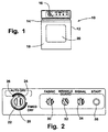
- a free-standing fabric drying appliance 10 having a cabinet 12 and a top panel 14. Extending upwardly from the top panel 14 is a control console 16 for mounting various control members as will be further described herein.
- the cabinet 12 further includes a front surface 18 having a hinged door 20 for accessing the interior of the dryer drum, as is known.
- FIG. 2 shows the control console is greater detail.
- a timer knob 22 is provided for allowing the dryer user to select an automatic cycle of operation and a timed dry cycle of operation. Specifically, the knob 22 may be rotated by the user to position the indicator marking 24 in the auto dry region 26 for selecting the automatic cycle of drying or the knob 22 may be rotated to position the indicator marking 24 in a timed dry region 26 for selecting the timed dry cycle. Within the auto dry region 28, the user may select between a "MORE DRY" position, a "NORMAL DRY" position and a “DAMP DRY” position. Within the timed dry region, the knob 22 may be rotated to select the desired quantity of drying time. Both the timed dry region and the auto dry region conclude with a WRINKLE GUARD portion and then terminate in an "OFF" position.
- the control console 16 further includes a fabric temperature selector dial 30 allowing the user to select between "NO HEAT”, “EXTRA LOW", “LOW”, “MEDIUM” and “HIGH” heat levels.
- the temperature selected by the user corresponds to the type of fabric being dried: HIGH for cotton items, MEDIUM for permanent press items, LOW for knit items and EXTRA LOW for hand washables.
- Selector dials 32 and 34 may also be provided for allowing the user to select the wrinkle guard feature and an end-of-cycle signal.
- a push-to-start button 36 is provided for allowing the user to initiate the dryer operation after the cycle selections have been made.
- the dryer 10 is provided with a unique hybrid electromechanical timer and microprocessor control system as shown in FIG. 3.
- the control circuitry includes three power supply conductors 38, 40 and 42 which are connectable with a three wire 240 volt, alternating current power source.
- the conductors 38 and 40 are connected with the power lines and that the neutral conductor 42 is connected to the earth grounded neutral line. It can be readily appreciated by one of ordinary skill in the art that the present invention is not limited to a 240 volt power supply but could also operate from a 120 volt power supply and a gas product supply.
- the control system of the present invention includes an electromechanical timer 44 and a microprocessor 46.
- the timer 44 includes a timer motor 48, a main switch 50 and an array of switches 52, 54 and 56.
- the main switch 50 is closed which supplies power to a power supply circuit, generally enclosed by broken line 58, such that a constant voltage level is supplied to the microprocessor 46.
- the switches 50, 52, 54 and 56 are cam operated switches which open and close in response to the timer cams, shown as 50c, 52c, 54c and 56c, driven by the timer motor 48.
- the switches 50, 52, 54 and 56 are connected to the microprocessor through lines 50a, 52a, 54a and 56a such that the switch status information is input to the microprocessor.
- the position of the timer knob 22 may be used to input to the microprocessor 46 the desired cycle of operation and to signal when various operations need to occur. For example, when just switch 50 is closed at the initiation of a dryer cycle, the microprocessor executes the timed dry operation.
- the microprocessor executes the automatic dry operation according to the selected dryness as will be discussed further below.
- the cams of the timer open and close the switches 52, 54 and 56 to supply signals to the microprocessor 46 to take certain actions.
- the three switches 52, 54 and 56 can be configured in eight different logic states which are used to communicate information to the microprocessor.
- the timer 44 serves as a means for inputting initial cycle operation information and also provides control information to the microprocessor 46 during the dryer cycle.
- more or fewer cams can be used to provide more or less information to the microprocessor and the particular number of switches and logic states described above is not meant to be a limitation on the present invention.
- Switches 62, 64 and 66 are associated with the fabric temperature selector 30 for inputting the selected temperature to the microprocessor on lines 62a, 64a and 66a.
- the switch 68 is associated with the wrinkle guard selector dial 32.
- Switches 70 and 72 are associated with the end of cycle signal selector knob 34.
- a push-to-start (PTS) switch 74 is associated with the push-to-start button 36.
- the PTS switch 74 is a momentary switch used to start the selected drying cycle.
- the status of the PST switch 74 is communicated to the microprocessor 46 on line 74a.
- the PTS switch 74 is wired in parallel with a motor relay 76 and supplies 120 VAC to the drum motor 78 through the timer switches.
- the microprocessor 46 latches the motor relay 76 by turning on transistor 80 within 200 ms of the PTS switch 74 closure. Accordingly, when the PTS switch releases, the motor 78 is supplied with power through the motor relay 76 switch.
- a pair of centrifugally operated switches 84 and 86 are associated with the motor and change status when the motor is energized and deenergized.
- Switch 84 disconnects the start winding of the motor after the initial motor start.
- Switch 86 is provided on line 90 such that when switch 86 is closed, 240 VAC power is supplied across a heater 92.
- the heater 92 is cycled on and off by the microprocessor 46 in response to input from the thermistor 94 located in the blower housing (not shown). Heater control is effected through operation of the heater relay 96 which is controlled via transistor 98.
- the upper and lower temperatures at which the thermistor cycles the heater 92 on and off are varied in response to the user's temperature setting selection made via selector knob 30.
- the table T1 shown below, illustrates the various temperature settings. Temperature Settings: Upper Temperatures: Lower Temperatures: HIGH 150°F 138°F MEDIUM 140°F 128°F LOW 125°F 115°F EXTRA LOW 115°F 105°F
- a door switch 100 associated with the hinged door 20 is connected in series with the motor 78.
- switch 100 opens, deenergizing the motor 78.
- the centrifugal switch 86 is opened, deenergizing the heater Reenergizing the motor requires closing the door 20 and pushing the PTS button 36.
- the control circuit shown in FIG. 3 further includes a means for sensing the moisture level of clothes within the dryer drum.
- the moisture sensing means includes a moisture sensor 102 having a pair of electrodes 104, 106 which are positioned within the dryer drum spaced apart from each other in such a manner as to come into contact with conductive materials such as wet fabrics as they are tumbled during a dry cycle.
- the electrodes 104, 106 are connected to a moisture sensing circuit 108, which is similar to the moisture sensing circuit disclosed in U.S. Pat. No. 4,385,452, to Deschaaf et al., herein incorporated by reference.
- the sensing circuit 108 provides input into the microprocessor 46 such that the microprocessor may detect when a current path is completed across the electrodes, which may be referred as a wet sample.
- the microprocessor repetitively reads the input from the sensor circuit at very short intervals. Specifically, the microprocessor sampling rate is four times per 60 Hz line cycle for a total of eight lines cycles. A wet signal is generated if during one of these sampling intervals, the microprocessor reads all wet samples. In this manner, 32 sequential wet samples during a sampling interval equals a wet signal. If during a counting period, the duration of which is pre-selected as explained herein below, the microprocessor reads a wet signal, the microprocessor resets a search counter.
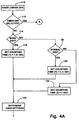
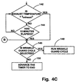
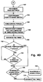
- FIGS. 4A, 4B, 4C, 4D, 5 and 6 illustrate the operation of the hybrid microprocessor/timer control system of the present invention during a drying cycle of operation.
- FIGS. 4A-4D are in functional block diagram form, with the various blocks indicating steps performed in sequenced during the performance of the method of the present invention.
- FIGS. 5 and 6 illustrate the timer switch encoding indicating the signals received by the microprocessor 46 during various periods of the timed dry cycle and automatic dry cycle.
- the first step 110 in the initiation of the dryer cycle is for the user to move the timer knob 22 to select a dryer cycle of operation. Either prior or subsequent to this step, the user inputs his desired dryer cycle options via the selector dials 30, 32 and 34.
- the microprocessor 46 reads the input from the timer to determine if the automatic cycle or timed cycle of drying has been selected. As shown in FIGS. 5, if only switch 50 is closed, the timed cycle is selected. As shown in FIG. 6, if the switch 50 along with either 53, 54 or 56 are selected, the automatic cycle is initiated according to the "MORE DRY", "NORMAL DRY" OR “DAMP DRY” option selected. It can be readily understood by one of ordinary skill in the art that fewer or more cycles could be used in the present invention. The automatic cycle will first be described and then the timed cycle.
- the microprocessor determines in step 114 if the "MORE DRY" option has been selected. If yes, in step 116, a counting time T is set to 7.5X seconds. If the "MORE DRY" cycle has not been selected, the microprocessor determine in step 118 if the "NORMAL DRY” option has been selected. If yes, in step 120, the counting time T is set to 3.75X seconds. If the "NORMAL DRY” has not been selected, the "DAMP DRY” option has been selected and the microprocessor, in step 122, sets the counting time T is set to X seconds. The value X is determined experimentally and is in the range of between 10-20. The counting time T is used to set a search counter.
- step 124 the microprocessor 46 reads the user selected cycle options. The user then initiates the cycle and energizes the motor by pressing the PTS button 36. The microprocessor enters the first counting period having time T as set above. In step 128, the processor looks for a wet signal during this first counting period. If no wet signals are sensed before the counter runs out, indicating the dryer load is dry or the drum is empty, the processor signals the timer to rapid advance to the WRINKLE GUARD position.
- step 132 the dryer continues to operate to dry clothes while the processor loops until no wet signals are detected during a counting period.
- the control regulates the temperature of the dryer, by switching transistor 98, in accordance with the sensed exhaust temperature and the selected temperature setting.
- the processor 46 drives the timer 44 at a set duty cycle to advance to the "DAMP DRY" position, as shown in step 134. This position can be sensed by the timer switch code, shown in FIG. 6, wherein switches 50 and 52 are closed. After advancing the timer 44, the dryer is operated for an "add-on" period of time, shown in step 136.
- the add-on time duration is determined in accordance with schedules, stored in the control memory, one of which is shown in FIG. 7 as an example.
- the add-on time is based upon three inputs: (1) the fabric cycle selected; (2) the dryness level that was selected; and (3) the duration of the drying cycle up to the point when a dry logic state was detected.
- the add-on time is closely tailored to the specific type of clothes being dried, the desired dryness level and the initial dryness condition of the clothes.
- the heat is reduced, as shown in step 138.
- the last five minutes of the add-on time is a reduced heat period.
- the timer 44 is advanced by the processor 46, shown in step 140, to the WRINKLE GUARD position. This position can be sensed by the processor 46 by monitoring the switching contacts 50, 52, 54 and 56. According to the switch code, shown in FIG. 6, the WRINKLE GUARD position is established when switches 50, 52 and 56 are closed. The clothes are then tumbled without heat until the exhaust temperature is less than T exhaust which may be in the range of 95°F-110°F, step 142, or until ten minutes has elapsed, step 144.
- step 146 the processor 46 determines whether a wrinkle guard option has been selected through operation of the selector dial 32. If yes, the dryer is operated through a wrinkle guard cycle, as shown in step 148. If no, the timer is advanced at 100% speed to the off position, in step 150, wherein switch 50 is opened and the processor is deenergized.
- step 112 the processor 46 cycles the dryer through a timed dry cycle, as shown in FIG. 4D.
- step 152 the microprocessor 46 reads the user selected cycle options. The user then initiates the cycle and energizes the motor by pressing the PTS button 36.
- step 156 the microprocessor then operates the dryer during the timed dry cycle for the selected time, driving the timer motor 48 at a predetermined duty cycle such that the timer knob 22 advances to show the dryer progress.
- the control regulates the temperature of the dryer in accordance with the sensed exhaust temperature and the selected temperature setting.
- the timer 44 is advanced by the processor 46 to the WRINKLE GUARD position, shown in step 160.
- the clothes are then tumbled without heat until the exhaust temperature is less than T exhaust , which may be in the range of 95°F-110° F, step 162, or until ten minutes has elapsed, step 164.
- the processor 46 determines whether a wrinkle guard option has been selected through operation of the selector dial 32. If yes, the dryer is operated through a wrinkle guard cycle, as shown in step 168. If no, the timer is advanced at 100% speed to the off position, in step 170, wherein switch 50 is opened and the processor is deenergized.
- the timer 44 is controlled in a manner to reflect the status of the dry cycle.
- the timer motor 48 is associated with a speed reducer gearing system 172 having an output shaft 174 for driving the timer knob 22, as shown in FIG. 8.
- a timer motor has a speed reducer gear system wherein the motor speed is greatly reduced to drive the output shaft of the speed reducer gear system at a relatively slow speed of rotation.
- a typical timer motor may be reduced in speed to drive a timer knob to make one 360° rotation in 3 hours (0.033°/sec or 0.00058 rad/sec).
- the present invention is such that the ratio between the motor 48 and the output shaft 174 causes the output shaft, and hence the timer knob, to be rotated relatively rapidly.
- the present invention is configured such that the timer knob 22 may be driven to make one complete 360° rotation in between 3 - 6 minutes. Accordingly, the rotational velocity of the timer knob is in the range between 1°/sec - 2 °/sec (or 0.017 rad/sec - 0.035 rad/sec).
- the processor 46 can drive the timer 44 in a relatively rapid manner when desired.
- the processor 46 can cycle the timer motor 48 on and off according to a plurality of predetermined duty cycles such that the timer 44 may be advanced at any of a plurality of predetermined speeds.
- the processor 46 controls transistor 80 to advance the timer 44 during different steps of the dry cycle. Specifically, the processor advances the timer during steps 134, 140 and step 150 of the automatic drying cycle and steps 156, 160 and 170 of the timed drying cycle. During steps 134 and 140, the timer operates the transistor 80 to achieve an 6% - 12% duty cycle wherein the timer motor 48 is periodically energized for a short time (2 ⁇ 8 seconds) and is then deenergized a period of time (25-40 seconds). As can be understood, under such a duty cycle, the timer knob 22 moves relatively slowly. For example, an 8% duty cycle results in movement of the timer knob from the NORMAL DRY position to the DAMP DRY position in approximately 10 minutes.
- step 1208 it is desired to rapidly advance the timer 44. For example, if during step 128, no wet signals are received during the first counting period, the timer is rapidly advance at 100% energization to the wrinkle guard position. Similarly, in step 150, since the dry cycle is over, the processor 46 advances the timer at 100% energization such that the timer rapidly moves to an end position.
- the processor 46 drives the timer motor 48 at a predetermined duty cycle wherein the timer motor 48 is periodically energized and then deenergized.
- the duty cycle may be 6% and the timer may be operated 7 seconds on, 113 seconds off.
- the timer knob 22 is driven to rotate at an appropriate rotational speed to provide an indication of the time cycle status.
- it is desired to move the timer knob rapidly wherein the processor drives the timer motor 48 at 100% energization. It can be seen, therefore, that the combination of the processor 46 and timer 44 allow for a responsive and rapid movement of the timer knob 22 to provide feed back to the user regarding the status of the dry cycle.
- a novel control system for a dryer combining an electronic circuit or microprocessor with a timer is provided.
- the control system is responsive to the moisture level of the clothes, provides feedback regarding the cycle status and operates to dry clothes in an efficient and rapid manner.
- the control system of the present invention may be readily applied to either an electric (120 volt or 240 volt) or gas combustion type dryer.
Landscapes
- Engineering & Computer Science (AREA)
- Textile Engineering (AREA)
- Control Of Washing Machine And Dryer (AREA)
- Detail Structures Of Washing Machines And Dryers (AREA)
Applications Claiming Priority (2)
| Application Number | Priority Date | Filing Date | Title |
|---|---|---|---|
| US146833 | 1980-05-05 | ||
| US09/146,833 US6047486A (en) | 1998-09-03 | 1998-09-03 | Control system for a dryer |
Publications (2)
| Publication Number | Publication Date |
|---|---|
| EP0984094A1 true EP0984094A1 (fr) | 2000-03-08 |
| EP0984094B1 EP0984094B1 (fr) | 2008-08-13 |
Family
ID=22519172
Family Applications (1)
| Application Number | Title | Priority Date | Filing Date |
|---|---|---|---|
| EP99117077A Expired - Lifetime EP0984094B1 (fr) | 1998-09-03 | 1999-08-31 | Dispositif de commande pour sèche-linge |
Country Status (5)
| Country | Link |
|---|---|
| US (1) | US6047486A (fr) |
| EP (1) | EP0984094B1 (fr) |
| BR (1) | BR9904076A (fr) |
| DE (1) | DE69939302D1 (fr) |
| ES (1) | ES2312197T3 (fr) |
Families Citing this family (39)
| Publication number | Priority date | Publication date | Assignee | Title |
|---|---|---|---|---|
| FR2801616B1 (fr) * | 1999-11-30 | 2002-03-01 | Electrolux Syst Blanchisserie | Procede de controle du sechage du linge dans un sechoir |
| US6199300B1 (en) * | 2000-03-01 | 2001-03-13 | Whirlpool Corporation | Method for energy efficient control of a dryer of clothes |
| US6845290B1 (en) * | 2000-05-02 | 2005-01-18 | General Electric Company | System and method for controlling a dryer appliance |
| US6446357B2 (en) * | 2000-06-30 | 2002-09-10 | Whirlpool Corporation | Fuzzy logic control for an electric clothes dryer |
| US6493963B1 (en) * | 2001-05-25 | 2002-12-17 | Maytag Corporation | Method and apparatus for dryness detection in a clothes dryer |
| US6519871B2 (en) | 2001-05-25 | 2003-02-18 | Maytag Corporation | Self programming clothes dryer system |
| US6505418B1 (en) | 2001-08-15 | 2003-01-14 | American Dryer Corporation | Apparatus and method for a clothing dryer having a fire protection system |
| CA2364067C (fr) | 2001-11-30 | 2007-01-09 | Camco Inc. | Systeme de commande de refroidissement pour secheuse |
| US7348690B2 (en) * | 2002-02-25 | 2008-03-25 | Alfred Wade Muldoon | Preventing unsafe operation by monitoring switching means |
| US20070256253A1 (en) * | 2002-04-08 | 2007-11-08 | Ogden J M | Method for delivering liquid fabric treating compositions to clothing in a clothes dryer |
| US6775924B2 (en) * | 2002-05-22 | 2004-08-17 | Maytag Corporation | Heater control system for a clothes dryer |
| US6757988B2 (en) | 2002-05-22 | 2004-07-06 | Maytag Corporation | Control system for a clothes dryer heater |
| US20040045187A1 (en) * | 2002-09-10 | 2004-03-11 | Andrew Corporation | Heatless and reduced-heat drying systems |
| DE10260149A1 (de) * | 2002-12-20 | 2004-07-01 | BSH Bosch und Siemens Hausgeräte GmbH | Vorrichtung zur Bestimmung des Leitwertes von Wäsche, Wäschetrockner und Verfahren zur Verhinderung von Schichtbildung auf Elektroden |
| KR100480930B1 (ko) * | 2003-08-12 | 2005-04-07 | 엘지전자 주식회사 | 의류건조기의 건조 잔류시간 검출방법 |
| DE10360867A1 (de) * | 2003-12-23 | 2005-07-21 | BSH Bosch und Siemens Hausgeräte GmbH | Verfahren und Vorrichtung zum Trocknen von Wäsche |
| KR100556806B1 (ko) * | 2004-05-13 | 2006-03-10 | 엘지전자 주식회사 | 의류건조기의 건조도 신호처리방법 |
| KR100710215B1 (ko) * | 2004-07-30 | 2007-04-20 | 엘지전자 주식회사 | 의류 건조기 및 그의 제어 방법 |
| US7474593B2 (en) * | 2005-03-08 | 2009-01-06 | Bobertshaw Controls Company | Variable delay appliance hybrid program timer |
| US20060201021A1 (en) * | 2005-03-14 | 2006-09-14 | Maytag Corporation | Clothes dryer wrinkle release cycle |
| US7475495B2 (en) * | 2005-04-18 | 2009-01-13 | Maytag Corporation | Dryness sensor for clothes dryer |
| CA2505565C (fr) * | 2005-04-28 | 2008-09-16 | Camco Inc. | Dispositif et methode de commande d'un seche-linge |
| US7594343B2 (en) * | 2006-02-14 | 2009-09-29 | Whirlpool Corporation | Drying mode for automatic clothes dryer |
| CN102978887B (zh) * | 2006-04-14 | 2015-04-01 | Lg电子株式会社 | 烘干机及其控制方法 |
| US7571553B2 (en) * | 2006-12-01 | 2009-08-11 | Electrolux Home Products, Inc. | Control user interface for laundry appliances |
| CA2629494A1 (fr) * | 2008-04-18 | 2009-10-18 | Mabe Canada Inc. | Secheuse avec dispositif de protection du cablage |
| US9580860B2 (en) * | 2009-12-18 | 2017-02-28 | Whirlpool Corporation | Method for operating a clothes dryer using load temperature determined by an infrared sensor |
| US8245415B2 (en) | 2009-12-18 | 2012-08-21 | Whirlpool Corporation | Method for determining load size in a clothes dryer using an infrared sensor |
| US8549770B2 (en) | 2009-12-18 | 2013-10-08 | Whirlpool Corporation | Apparatus and method of drying laundry with drying uniformity determination |
| US8474152B2 (en) | 2010-10-08 | 2013-07-02 | Whirlpool Corporation | Method to detect an empty load in a clothes dryer |
| US8468717B2 (en) | 2010-10-08 | 2013-06-25 | Whirlpool Corporation | Method to detect an end of cycle in a clothes dryer |
| US10612274B2 (en) * | 2012-02-10 | 2020-04-07 | Illinois Tool Works Inc. | Thermally actuated dryer door lock |
| JP6040418B2 (ja) * | 2012-09-04 | 2016-12-07 | パナソニックIpマネジメント株式会社 | 衣類乾燥機 |
| US10669668B2 (en) | 2017-11-28 | 2020-06-02 | Mark Goodson | Clothes dryer fire reduction system |
| WO2019108009A1 (fr) * | 2017-12-01 | 2019-06-06 | 엘지전자 주식회사 | Sèche-linge et son procédé de commande |
| DE102018213108A1 (de) * | 2018-08-06 | 2020-02-06 | E.G.O. Elektro-Gerätebau GmbH | Wäschetrockner und Verfahren zum Trocknen von Wäsche mit einem Wäschetrockner |
| US20200087844A1 (en) * | 2018-09-18 | 2020-03-19 | Sherrilynn Griffin-Nelson | Automated Clothes Dryer Assembly |
| EP3964628A1 (fr) * | 2020-09-04 | 2022-03-09 | LG Electronics Inc. | Appareil de traitement du linge |
| US12448726B2 (en) * | 2021-02-01 | 2025-10-21 | Electrolux Consumer Products, Inc. | Laundry dryer control system |
Citations (4)
| Publication number | Priority date | Publication date | Assignee | Title |
|---|---|---|---|---|
| GB2063441A (en) * | 1979-10-01 | 1981-06-03 | Hoover Ltd | Tumbler Dryer |
| DE3440038A1 (de) * | 1984-11-02 | 1986-05-07 | Licentia Patent-Verwaltungs-Gmbh, 6000 Frankfurt | Steuerungsanordnung fuer einen nach dem trommelprinzip arbeitenden waeschetrockner |
| FR2598443A1 (fr) * | 1986-05-08 | 1987-11-13 | Candy Elettrodomestici | Dispositif de commande pour le deroulement des programmes, en particulier pour machines a laver |
| EP0504052A1 (fr) * | 1991-03-12 | 1992-09-16 | Ciapem | Appareil électroménager à programmateur comprenant une base de temps électromécanique et une base de temps électronique |
Family Cites Families (23)
| Publication number | Priority date | Publication date | Assignee | Title |
|---|---|---|---|---|
| US3059344A (en) * | 1958-05-26 | 1962-10-23 | Mc Graw Edison Co | Control system for laundry dryers |
| US3401464A (en) * | 1966-09-23 | 1968-09-17 | Gen Motors Corp | Clothes dryer with single dial controller |
| US3471938A (en) * | 1967-10-04 | 1969-10-14 | Whirlpool Co | Electronic control circuit for a dryer with timer runout |
| US3714717A (en) * | 1970-12-11 | 1973-02-06 | Whirlpool Co | Knit cycle for clothes dryer |
| US3762064A (en) * | 1971-11-12 | 1973-10-02 | Whirlpool Co | Timer with cycle and time dependent runout for dryer |
| DE3030864C2 (de) * | 1980-08-14 | 1985-04-25 | Bosch-Siemens Hausgeräte GmbH, 7000 Stuttgart | Verfahren zum automatischen Steuern des Trocknungsvorganges in einem Wäschetrocknungssystem und Einrichtung zur Durchführung des Verfahrens |
| US4385452A (en) * | 1981-06-03 | 1983-05-31 | Whirlpool Corporation | Low voltage sensor for dryer |
| US4422247A (en) * | 1981-06-29 | 1983-12-27 | Whirlpool Corporation | Low voltage sensor for a dryer |
| US4397101A (en) * | 1981-09-10 | 1983-08-09 | General Electric Company | Automatic dryer control |
| JPS58221996A (ja) * | 1982-06-17 | 1983-12-23 | 松下電器産業株式会社 | 衣類乾燥機 |
| US4477982A (en) * | 1982-09-27 | 1984-10-23 | The Maytag Company | Microcontroller-based dryer control |
| US5128661A (en) * | 1982-10-12 | 1992-07-07 | Robertshaw Controls Company | Solid state rotary entry control system |
| US4738034A (en) * | 1985-12-16 | 1988-04-19 | Kabushiki Kaisha Toshiba | Drying machine |
| JP2966461B2 (ja) * | 1990-03-09 | 1999-10-25 | 株式会社日立製作所 | 洗濯機の制御装置 |
| US5291667A (en) * | 1990-04-26 | 1994-03-08 | White Consolidated Industries, Inc. | Electronic control of clothes dryer |
| US5211037A (en) * | 1990-08-13 | 1993-05-18 | Raytheon Company | Controller for washing machine with alternately reversing drive motor |
| US5113124A (en) * | 1990-09-04 | 1992-05-12 | Eaton Corporation | Programmable appliance controller |
| US5204600A (en) * | 1991-02-06 | 1993-04-20 | Hewlett-Packard Company | Mechanical detent simulating system |
| JP3004455B2 (ja) * | 1992-03-27 | 2000-01-31 | 株式会社東芝 | 乾燥機 |
| US5189355A (en) * | 1992-04-10 | 1993-02-23 | Ampex Corporation | Interactive rotary controller system with tactile feedback |
| IT226476Z2 (it) * | 1992-04-14 | 1997-06-24 | Whirlpool Italia | Dispositivo atto a controllare e comandare il funzionamento di una lavabiancheria o similare o altro elettrodomestico quale piano di cottura forno o similare con manopola servoassistita |
| JPH078691A (ja) * | 1993-06-24 | 1995-01-13 | Toshiba Corp | 衣類乾燥機 |
| US5570520A (en) * | 1995-05-17 | 1996-11-05 | Eaton Corporation | Clothes dryer dryness detection system |
-
1998
- 1998-09-03 US US09/146,833 patent/US6047486A/en not_active Expired - Fee Related
-
1999
- 1999-08-31 EP EP99117077A patent/EP0984094B1/fr not_active Expired - Lifetime
- 1999-08-31 DE DE69939302T patent/DE69939302D1/de not_active Expired - Lifetime
- 1999-08-31 ES ES99117077T patent/ES2312197T3/es not_active Expired - Lifetime
- 1999-09-03 BR BR9904076-0A patent/BR9904076A/pt not_active Application Discontinuation
Patent Citations (4)
| Publication number | Priority date | Publication date | Assignee | Title |
|---|---|---|---|---|
| GB2063441A (en) * | 1979-10-01 | 1981-06-03 | Hoover Ltd | Tumbler Dryer |
| DE3440038A1 (de) * | 1984-11-02 | 1986-05-07 | Licentia Patent-Verwaltungs-Gmbh, 6000 Frankfurt | Steuerungsanordnung fuer einen nach dem trommelprinzip arbeitenden waeschetrockner |
| FR2598443A1 (fr) * | 1986-05-08 | 1987-11-13 | Candy Elettrodomestici | Dispositif de commande pour le deroulement des programmes, en particulier pour machines a laver |
| EP0504052A1 (fr) * | 1991-03-12 | 1992-09-16 | Ciapem | Appareil électroménager à programmateur comprenant une base de temps électromécanique et une base de temps électronique |
Also Published As
| Publication number | Publication date |
|---|---|
| DE69939302D1 (de) | 2008-09-25 |
| US6047486A (en) | 2000-04-11 |
| ES2312197T3 (es) | 2009-02-16 |
| BR9904076A (pt) | 2000-08-29 |
| EP0984094B1 (fr) | 2008-08-13 |
Similar Documents
| Publication | Publication Date | Title |
|---|---|---|
| US6047486A (en) | Control system for a dryer | |
| US6020698A (en) | Timer for use with an electronic control in controlling an appliance | |
| US6493963B1 (en) | Method and apparatus for dryness detection in a clothes dryer | |
| CA1173132A (fr) | Senseur a basse tension pour secheuse | |
| US6199300B1 (en) | Method for energy efficient control of a dryer of clothes | |
| US6446357B2 (en) | Fuzzy logic control for an electric clothes dryer | |
| CA2373976C (fr) | Systeme de seche-linge autoprogrammable | |
| US4422247A (en) | Low voltage sensor for a dryer | |
| US4330081A (en) | Water temperature control system for a clothes washing machine | |
| US3762064A (en) | Timer with cycle and time dependent runout for dryer | |
| US6775924B2 (en) | Heater control system for a clothes dryer | |
| GB2279448A (en) | Tumble dryer control | |
| GB2269243A (en) | Drying machine | |
| US3398460A (en) | Anti-wrinkle cycle for dryers with intermittent signaling means | |
| EP0428846B1 (fr) | Séchoir à tambour | |
| US6819255B2 (en) | Load size detection in a fabric dryer | |
| JPH05277294A (ja) | 衣類乾燥機 | |
| CA1281183C (fr) | Commande de seche-linge a culbutement en alternance | |
| CA1095151A (fr) | Circuit de controle pour secheuse | |
| CA1166036A (fr) | Methode et machine de lavage d'articles textiles | |
| US3394465A (en) | Dryer with anti-werinkle cycle | |
| US3398462A (en) | Dryer with antiwrinkle cycle | |
| US4312138A (en) | Control system for fabric drying apparatus | |
| EP0863244A2 (fr) | Sécheur à tambour | |
| US3365809A (en) | Anti-wrinkle cycle dryer with slow rotation |
Legal Events
| Date | Code | Title | Description |
|---|---|---|---|
| PUAI | Public reference made under article 153(3) epc to a published international application that has entered the european phase |
Free format text: ORIGINAL CODE: 0009012 |
|
| AK | Designated contracting states |
Kind code of ref document: A1 Designated state(s): DE ES FR GB IT SE |
|
| AX | Request for extension of the european patent |
Free format text: AL;LT;LV;MK;RO;SI |
|
| 17P | Request for examination filed |
Effective date: 20000810 |
|
| AKX | Designation fees paid |
Free format text: DE ES FR GB IT SE |
|
| 17Q | First examination report despatched |
Effective date: 20021219 |
|
| GRAP | Despatch of communication of intention to grant a patent |
Free format text: ORIGINAL CODE: EPIDOSNIGR1 |
|
| GRAS | Grant fee paid |
Free format text: ORIGINAL CODE: EPIDOSNIGR3 |
|
| GRAA | (expected) grant |
Free format text: ORIGINAL CODE: 0009210 |
|
| AK | Designated contracting states |
Kind code of ref document: B1 Designated state(s): DE ES FR GB IT SE |
|
| REG | Reference to a national code |
Ref country code: GB Ref legal event code: FG4D |
|
| REF | Corresponds to: |
Ref document number: 69939302 Country of ref document: DE Date of ref document: 20080925 Kind code of ref document: P |
|
| REG | Reference to a national code |
Ref country code: SE Ref legal event code: TRGR |
|
| REG | Reference to a national code |
Ref country code: ES Ref legal event code: FG2A Ref document number: 2312197 Country of ref document: ES Kind code of ref document: T3 |
|
| PLBE | No opposition filed within time limit |
Free format text: ORIGINAL CODE: 0009261 |
|
| STAA | Information on the status of an ep patent application or granted ep patent |
Free format text: STATUS: NO OPPOSITION FILED WITHIN TIME LIMIT |
|
| 26N | No opposition filed |
Effective date: 20090514 |
|
| PGFP | Annual fee paid to national office [announced via postgrant information from national office to epo] |
Ref country code: ES Payment date: 20100915 Year of fee payment: 12 |
|
| PGFP | Annual fee paid to national office [announced via postgrant information from national office to epo] |
Ref country code: SE Payment date: 20100812 Year of fee payment: 12 Ref country code: IT Payment date: 20100823 Year of fee payment: 12 Ref country code: FR Payment date: 20100824 Year of fee payment: 12 Ref country code: DE Payment date: 20100825 Year of fee payment: 12 |
|
| PGFP | Annual fee paid to national office [announced via postgrant information from national office to epo] |
Ref country code: GB Payment date: 20100825 Year of fee payment: 12 |
|
| GBPC | Gb: european patent ceased through non-payment of renewal fee |
Effective date: 20110831 |
|
| REG | Reference to a national code |
Ref country code: FR Ref legal event code: ST Effective date: 20120430 |
|
| PG25 | Lapsed in a contracting state [announced via postgrant information from national office to epo] |
Ref country code: IT Free format text: LAPSE BECAUSE OF NON-PAYMENT OF DUE FEES Effective date: 20110831 |
|
| REG | Reference to a national code |
Ref country code: DE Ref legal event code: R119 Ref document number: 69939302 Country of ref document: DE Effective date: 20120301 |
|
| REG | Reference to a national code |
Ref country code: SE Ref legal event code: EUG |
|
| PG25 | Lapsed in a contracting state [announced via postgrant information from national office to epo] |
Ref country code: GB Free format text: LAPSE BECAUSE OF NON-PAYMENT OF DUE FEES Effective date: 20110831 Ref country code: FR Free format text: LAPSE BECAUSE OF NON-PAYMENT OF DUE FEES Effective date: 20110831 |
|
| PG25 | Lapsed in a contracting state [announced via postgrant information from national office to epo] |
Ref country code: SE Free format text: LAPSE BECAUSE OF NON-PAYMENT OF DUE FEES Effective date: 20110901 |
|
| REG | Reference to a national code |
Ref country code: ES Ref legal event code: FD2A Effective date: 20130606 |
|
| PG25 | Lapsed in a contracting state [announced via postgrant information from national office to epo] |
Ref country code: DE Free format text: LAPSE BECAUSE OF NON-PAYMENT OF DUE FEES Effective date: 20120301 |
|
| PG25 | Lapsed in a contracting state [announced via postgrant information from national office to epo] |
Ref country code: ES Free format text: LAPSE BECAUSE OF NON-PAYMENT OF DUE FEES Effective date: 20110901 |