EP0984128A2 - Dispositif de couplage entre un compas et une charnière du côté de l'aile pour fenêtre pivotante et basculante - Google Patents
Dispositif de couplage entre un compas et une charnière du côté de l'aile pour fenêtre pivotante et basculante Download PDFInfo
- Publication number
- EP0984128A2 EP0984128A2 EP99115304A EP99115304A EP0984128A2 EP 0984128 A2 EP0984128 A2 EP 0984128A2 EP 99115304 A EP99115304 A EP 99115304A EP 99115304 A EP99115304 A EP 99115304A EP 0984128 A2 EP0984128 A2 EP 0984128A2
- Authority
- EP
- European Patent Office
- Prior art keywords
- leg
- arm
- connection according
- pin
- opening
- Prior art date
- Legal status (The legal status is an assumption and is not a legal conclusion. Google has not performed a legal analysis and makes no representation as to the accuracy of the status listed.)
- Granted
Links
- 230000008878 coupling Effects 0.000 title description 8
- 238000010168 coupling process Methods 0.000 title description 8
- 238000005859 coupling reaction Methods 0.000 title description 8
- 239000002184 metal Substances 0.000 claims description 4
- 210000002414 leg Anatomy 0.000 description 63
- 210000000689 upper leg Anatomy 0.000 description 9
- 230000015572 biosynthetic process Effects 0.000 description 5
- CMWTZPSULFXXJA-VIFPVBQESA-N naproxen Chemical compound C1=C([C@H](C)C(O)=O)C=CC2=CC(OC)=CC=C21 CMWTZPSULFXXJA-VIFPVBQESA-N 0.000 description 4
- 241000283707 Capra Species 0.000 description 1
- 239000004744 fabric Substances 0.000 description 1
- 230000004313 glare Effects 0.000 description 1
- 238000007493 shaping process Methods 0.000 description 1
- 230000007704 transition Effects 0.000 description 1
Images


Classifications
-
- E—FIXED CONSTRUCTIONS
- E05—LOCKS; KEYS; WINDOW OR DOOR FITTINGS; SAFES
- E05D—HINGES OR SUSPENSION DEVICES FOR DOORS, WINDOWS OR WINGS
- E05D15/00—Suspension arrangements for wings
- E05D15/48—Suspension arrangements for wings allowing alternative movements
- E05D15/52—Suspension arrangements for wings allowing alternative movements for opening about a vertical as well as a horizontal axis
- E05D15/5205—Suspension arrangements for wings allowing alternative movements for opening about a vertical as well as a horizontal axis with horizontally-extending checks
-
- E—FIXED CONSTRUCTIONS
- E05—LOCKS; KEYS; WINDOW OR DOOR FITTINGS; SAFES
- E05Y—INDEXING SCHEME ASSOCIATED WITH SUBCLASSES E05D AND E05F, RELATING TO CONSTRUCTION ELEMENTS, ELECTRIC CONTROL, POWER SUPPLY, POWER SIGNAL OR TRANSMISSION, USER INTERFACES, MOUNTING OR COUPLING, DETAILS, ACCESSORIES, AUXILIARY OPERATIONS NOT OTHERWISE PROVIDED FOR, APPLICATION THEREOF
- E05Y2900/00—Application of doors, windows, wings or fittings thereof
- E05Y2900/10—Application of doors, windows, wings or fittings thereof for buildings or parts thereof
- E05Y2900/13—Type of wing
- E05Y2900/148—Windows
Definitions
- the invention relates to a detachable connection between the ax arm and the leaf-side hinge for tilt-and-turn windows according to the preamble of claim 1.
- EP 06 00 103 B1 is a couplable connection of the type mentioned here.
- This detachable connection also has an extension arm designated ax arm, which by means of a Coupling bracket attached to a wing-side hinge is.
- the hitch angle includes an ax and a wing-side leg.
- the wing-side leg has a crank web, a first and a second leg as well one between the first and second leg Intermediate leg, which essentially perpendicular to both legs of the goat bar runs.
- the known detachable connection reach through the middle leg and the second Thigh breakthroughs on a band trained Support part. This supports the first leg of the crank bar on the front of the support part from.
- the second leg is supported on the back of the support part. Because the hitch angle the longitudinal extension is provided of the support part substantially parallel to the axis of rotation of the wing-side hinge.
- DE 42 32 945 C1 is a hinge fitting known for windows, doors or the like are designed as so-called turn-tilt wings.
- the known hinge fitting has a wing-side Tape that has a support member which extends across the axis of rotation of the belt. In the support part engages an ax arm.
- This task is done with a detachable connection solved, which has the features of claim 1.
- This detachable connection is between the too referred to as stay arm and the wing-side Band used for tilt-and-turn windows.
- a crank bar that one first and a second leg and one between the first and second leg Has thighs.
- a breakthrough for taking up the thigh provided, with the first leg the front and the second leg on the Back of a support part with the breakthrough supports.
- the support part is transverse, in particular at right angles extends to the axis of rotation of the belt, and that the second leg of the crank bar in the plane of the Axerarms lies.
- the shape of the edge contour the opening and / or the pocket of the design the edge contour of the first leg and / or the Corresponds to thighs will be an exact fit between the Kröpfsteg and the breakthrough respectively the bag realized so that in Swivel direction of the ax arm with respect to the belt there is little play.
- Will put a bag on the front and back are formed on the opening will also be a coupling point respectively Connection point for right / left stop of the Band formed, the coupling point in particular can be used when between glare and Sash frame there is little clearance.
- the second leg of the crank web is in one piece is formed with the ax arm, preferably it is provided that a section of the Axerarms forms this second leg. Moreover it is preferably provided that the crank web in one piece is formed with the ax arm.
- the ax arm together with the crank web as a sheet metal part, especially sheet metal stamping, whose production is particularly inexpensive.
- the band is a cast and / or milled part. So is this tape can be manufactured with particularly low tolerances. Also have cast and / or milled parts a particularly high strength. Moreover, can to the curved ones known in the prior art Belt parts are dispensed with.
- first leg is free Extended towards the end, being the extension thus formed engages in the pocket.
- detachable connection especially for Suitable for absorbing torsional moments because this extension of the first leg at the bottom of the Bag supports, being particularly advantageous is that by expanding even at already small torsion angles of the legs respectively the extension at the bottom of the bag creates.
- the detachable connection according to the invention is also characterized by a low game - around the torsion axis - between the arm and the belt out.
- the cone is towards its free end enlarged or enlarged in diameter.
- the pin immediately on the second Thigh, the pin has a smaller diameter than at its free end.
- the hump formation occurs consequently especially in the connection area between Ax arm and wing-side hinge on.
- the conical Design of the pin and the recess intended When force is applied to the detachable Connection is based on the conical pin the wall of the recess. Because the Wall and the pin are conical, a stop surface is formed which prevents that the pin is pulled out of the recess could be. This leaves the second leg of the cropping bar flat on the support part of the band lying on. The hump formation is thus prevented.
- a screw in particular countersunk screw, is used, which is provided in a on the support member Thread engages that in the recess is introduced.
- a preferred embodiment stands out characterized in that the tape including its support member symmetrical to a central plane is perpendicular to the axis of rotation of the belt stands. So that the tape can be used for both right and also used for sash frames hinged on the left become.
- the pin receiving breakthrough of the support part to the median plane double cone-shaped. That is, the Breakthrough shows a constriction that is approximately in the middle plane. Based on this constriction the breakthrough extends to both Top as well as the bottom of the support part.
- a particularly preferred embodiment of the Crank portion is characterized in that the free The end of the first leg expanded like a hammer is trained.
- the second Thigh in the transition area to the thigh tapered, including part of the first leg can be made narrower than the second Leg. At the narrow area of the first leg then the above mentioned closes hammer head-shaped extension.
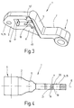
- Figure 1 shows a tape 1 for the casement one Window, the window as a rotating and / or Tilt window can be realized.
- Volume 1 points a bearing part 2 and a support part 3.
- a bearing eye 4 is provided through which a bearing pin, not shown here, for the purpose rotatable connection of the band part with one here not shown, on the window frame attached bearing part is insertable.
- To the Bearing eye 4 closes a connector 5 on, which merges into the support part 3, that is, bearing part 2 and support part 3 are on the connector 5 connected to each other.
- Bearing eye 4 and Support part 3 are assigned to each other so that their Center axes are at a distance from each other.
- the band 1 is preferably in one piece as a cast and / or Milled part trained.
- the tape 1 has an opening 6, the Support part 3 from the front 7 to the rear 8 interspersed.
- the breakthrough 6 has an approximately rectangular section 9, the approximately is centered in the support part 3.
- Towards the connector 5 follows section 9 a semicircular section 10 which in turn is roughly rectangular continues section 11.
- the width W of section 11 is, however, significantly smaller than the width B of section 9.
- the Diameter V of section 10 corresponds approximately to that Width B of section 9.
- Section 11 ends preferably just before the connector 5. Die Sections 9, 10 and 11 of the opening 6 are closed a symmetrical central longitudinal plane, with a central longitudinal axis in the central longitudinal plane 12 of the support part 3 lies.
- the pockets 13 and 13 ' have an edge contour, which - starting at section 9 - initially straight extends towards the connector 5.
- the width is preferably identical like the width B of section 9.
- the height of the middle of section 11 expands Pocket 13 in width, so that the pocket 13 a has approximately hammer-shaped contour.
- FIG. 1 there is a right next to the opening 6 Recess 14 in the support part 3, which preferably as circular breakthrough 15 is realized.
- This Breakthrough 15 is like breakthrough 6 and the Pocket 13 or 13 'symmetrical to the central longitudinal plane of the support part 3, in which the central longitudinal axis 12 lies.
- the support part 3 a has a smaller thickness than the connecting piece 5 and the bearing eye 4.
- the band 1 is to a central plane E symmetrical, on one Axis of rotation D of the band 1 is perpendicular.
- FIG. 3 The perspective of tape 1 shown in FIG. 3 shows particularly well the pocket 13 ', which like the pocket 13 has a depth such that a Web 16 is formed, which is preferably symmetrical to the central plane E ( Figure 2).
- the web 16 is the section 11 of the breakthrough 6.
- FIG. 3 shows a wall 17 of the opening 6, the wall 17 adjacent to the opening 15 and to the recess 14.
- the wall 17 is curved. That is, starting from the rear 8 or from its edge 18th the wall 17 runs obliquely in the direction of the Middle plane E ( Figure 2) and towards the Web 16.
- On this sloping wall section includes one perpendicular to the median plane E standing wall section, which then in turn passes over a sloping wall section, which runs away from the web 16 and on the Front 7 of the support part 3 ends.
- Figure 4 shows a second embodiment of a Band 1, which is opposite the band according to FIG. 1 differs only in that one in the Thick reinforced connector 5, bearing part 2 and thus also a thicker bearing eye 4 is provided is.
- 4 is in the region of the recess 14 or the opening 15, the support part 3rd shown cut.
- the opening 15 widens in diameter, so that in the plane of the front 7 is larger in diameter than in the central plane E.
- the section below the central plane E. breakthrough 15 also widens starting from the central plane E in diameter, so that in the plane of the back 8 a larger one Diameter of the opening 15 is present in the Middle plane E.
- the opening 15 thus has a conical shape Walls 19 and 20, wherein in the embodiment according to Figure 4 it is provided that this Walls 19 and 20 are formed by partial circles, whose centers lie in the middle plane E.
- this Walls 19 and 20 are formed by partial circles, whose centers lie in the middle plane E.
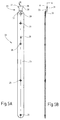
- FIG. 5A shows what is also referred to as a raising arm Axer arm 22 in plan view.
- the ax arm is in preferred embodiment as a stamped sheet metal part 23 and thus preferably realized in one piece.
- the opening 24 - decade the Ax arm 22 can be used for a tilt and turn window should- a bearing pin is inserted so that -when the window is tilted-the Axle arm 22 has been pivoted around the bearing pin.
- the arm 22 on a tilt and turn window used is preferably in another Opening 29 introduced a locking bolt, so that switching from the tilt open position in the rotary opening position is possible.
- the ax arm 22 has a crank web 30 5B, which has a first leg 31 according to FIG and a second leg 32 and one the first and connecting the second leg 31 and 32 Has intermediate leg 33.
- the thigh 33 extends approximately at right angles to the second Leg 32 and then goes into the first leg 31 over, so that the first and the second leg 31 and 32 are approximately parallel to each other Levels A and B lie.
- the opening 28 is introduced, the provided for receiving a pin 34 ( Figure 8) is, the pin 34 is approximately the same Direction as the intermediate leg 33 extends.
- the second leg tapers 32, so that the intermediate leg 33 is less Has width than the second leg 32.
- the first Leg 31 has the same width in some areas on like the intermediate leg 33, in particular it is provided that at the free end 35 of the first Leg 31 an extension 36 is formed.
- the first leg 31 and the extension 36 show in plan view a hammer-like contour, so that rag 37 and 38 at the free end 35 of the first leg 31 are formed. It is preferably provided that the shape of the edge contour of the first leg 31 and / or the intermediate leg 33 of the shaping the edge contour of the opening 6 and / or corresponds to the pocket 13 or 13 '.
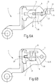
- the arm 22, the first and second legs 31 and 32 and the Intermediate legs 33 are formed in one piece, the leg 32 from a portion of the ax arm 22 is formed.
- the arm 22 is thus on the front 7 of volume 1, that the intermediate leg 33 and the first leg 31 with her Place the narrow side on the front 7.
- the tab 38 protrudes into the opening 6.
- the arm 22 is about a pivot axis 39th panned by the plant between the first Leg 31 and wall 17 is formed.
- the ax arm 22 is moved through 90 ° about the pivot axis 39 in such a way that the second leg 32 from the image plane is pivoted upwards.
- the ax arm 22 so that it out of the plane protrudes as indicated in Figure 6B.
- the first leg 31 thus engages through the opening 6 through, with the tab 38 adjacent to the rear 8 of the support part 3.
- the cloth 37 was during the pivoting of the arm 22 by moved through the section 11 of the opening 6, so that this tab 37 is adjacent to the back 8 of the support part 3 lies.
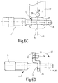
- FIG 6C shows the tape 1 and the arm 22 of the Figure 6B in side view.
- the first leg 31 has passed through the opening 6 is so that the free end 35 of the Axle arm 22 on the rear 8 of the support part 3 lies.
- connection 44 between the arm 22 and the wing-side hinge 1 characterized in that the connection 44 in the Horizontal lies, whereby on the one hand from the Coupling angles known from the prior art are dispensed with can be. On the other hand, the whole stands out Connection 44 by a low profile.
- connection 44 also has a high stability on, since corresponding for all load directions Facilities are provided that prevent that the connection 44 is uncoupled again.
- a relative rotation (arrow P in Figure 7) of the Axer arm 22 with respect to the belt 1 is prevented that the first leg 31 on walls of the breakthrough 6 is supported.
- connection 44 can thus a band 1 and an ax arm 2 both for right as well as for left wing frames be used.
Landscapes
- Engineering & Computer Science (AREA)
- Mechanical Engineering (AREA)
- Hinges (AREA)
- Pivots And Pivotal Connections (AREA)
- Buckles (AREA)
- Jib Cranes (AREA)
- Closing And Opening Devices For Wings, And Checks For Wings (AREA)
Applications Claiming Priority (2)
| Application Number | Priority Date | Filing Date | Title |
|---|---|---|---|
| DE19839410A DE19839410C1 (de) | 1998-08-29 | 1998-08-29 | Kuppelbare Verbindung zwischen Axerarm und flügelseitigem Band für Dreh-Kippfenster |
| DE19839410 | 1998-08-29 |
Publications (3)
| Publication Number | Publication Date |
|---|---|
| EP0984128A2 true EP0984128A2 (fr) | 2000-03-08 |
| EP0984128A3 EP0984128A3 (fr) | 2001-10-24 |
| EP0984128B1 EP0984128B1 (fr) | 2005-04-27 |
Family
ID=7879164
Family Applications (1)
| Application Number | Title | Priority Date | Filing Date |
|---|---|---|---|
| EP99115304A Expired - Lifetime EP0984128B1 (fr) | 1998-08-29 | 1999-08-03 | Dispositif de couplage entre un compas et une charnière du côté de l'aile pour fenêtre pivotante et basculante |
Country Status (3)
| Country | Link |
|---|---|
| EP (1) | EP0984128B1 (fr) |
| AT (1) | ATE294313T1 (fr) |
| DE (2) | DE19839410C1 (fr) |
Citations (2)
| Publication number | Priority date | Publication date | Assignee | Title |
|---|---|---|---|---|
| DE4232945C1 (de) | 1992-10-01 | 1993-11-18 | Siegenia Frank Kg | Scharnierbeschlag für Fenster, Türen od. dgl. |
| EP0600103B1 (fr) | 1992-10-29 | 1994-10-05 | W. Hautau Gmbh | Pivot positionnable à droite ou à gauche pour dispositifs déflecteurs |
Family Cites Families (3)
| Publication number | Priority date | Publication date | Assignee | Title |
|---|---|---|---|---|
| AT391734B (de) * | 1987-09-18 | 1990-11-26 | Mayer & Co Riegel Beschlag | Ausstellvorrichtung fuer den drehkippfluegel eines fensters oder einer tuer |
| DE19601326C2 (de) * | 1996-01-16 | 1999-03-11 | Jakob Escher Gmbh | Ausstellvorrichtung für Drehkippflügel |
| DE19623403C1 (de) * | 1996-06-12 | 1997-08-14 | Aubi Baubeschlaege Gmbh | Lösbare Verbindung für ein Kipp-, Kippschiebe- oder Kippschwenkfenster |
-
1998
- 1998-08-29 DE DE19839410A patent/DE19839410C1/de not_active Expired - Fee Related
-
1999
- 1999-08-03 AT AT99115304T patent/ATE294313T1/de active
- 1999-08-03 EP EP99115304A patent/EP0984128B1/fr not_active Expired - Lifetime
- 1999-08-03 DE DE59911971T patent/DE59911971D1/de not_active Expired - Lifetime
Patent Citations (2)
| Publication number | Priority date | Publication date | Assignee | Title |
|---|---|---|---|---|
| DE4232945C1 (de) | 1992-10-01 | 1993-11-18 | Siegenia Frank Kg | Scharnierbeschlag für Fenster, Türen od. dgl. |
| EP0600103B1 (fr) | 1992-10-29 | 1994-10-05 | W. Hautau Gmbh | Pivot positionnable à droite ou à gauche pour dispositifs déflecteurs |
Also Published As
| Publication number | Publication date |
|---|---|
| EP0984128B1 (fr) | 2005-04-27 |
| DE19839410C1 (de) | 2000-01-13 |
| DE59911971D1 (de) | 2005-06-02 |
| ATE294313T1 (de) | 2005-05-15 |
| EP0984128A3 (fr) | 2001-10-24 |
Similar Documents
| Publication | Publication Date | Title |
|---|---|---|
| AT401669B (de) | Verdeckt angeordneter beschlag für schwenklager, insbesondere für kipp-schwenklager-flügel von fenstern und türen | |
| DE3872442T2 (de) | Drehbeschlag eines drehkippfluegels einer tuer eines fensters oder von aehnlichem. | |
| DE2364632A1 (de) | Kraftfahrzeugsicherheitseinrichtung | |
| DE3405343C2 (fr) | ||
| DD295407A5 (de) | Scharnier | |
| DE19650085C2 (de) | Unteres Ecklager für ein Kipp-Schwenkfenster, eine Kipp-Schwenktür oder dergleichen | |
| DE60010806T2 (de) | Verdeckter Öffnungsbeschlag für Drehflügeltür oder -Fenster | |
| CH434026A (de) | Ausstellvorrichtung für Fenster, Türen, Klappen oder dergleichen | |
| DE1810671A1 (de) | Stelleinrichtung an Fenstern,Tueren od.dgl. | |
| DE3033713C2 (fr) | ||
| DE2040525A1 (de) | Fenster oder Tuer mit Fluegel und Rahmen,insbesondere aus Metall- oder Kunststoff-Hohlprofilen | |
| EP0984128B1 (fr) | Dispositif de couplage entre un compas et une charnière du côté de l'aile pour fenêtre pivotante et basculante | |
| DE2157014A1 (de) | Eckverbindung fuer zwei holmenden des rahmens eines fensters, einer tuere oder dergl | |
| EP0033877A1 (fr) | Fenêtre ou porte | |
| DE19607931C2 (de) | Dachfenster | |
| EP0874123B1 (fr) | Ferrure pour supporter l'aile pivotante d'une fenêtre ou porte | |
| DE3813088A1 (de) | Doppelgelenkscharnier zur anlenkung einer fluegeltuer an einer feststehenden wand eines nutzfahrzeugaufbaus | |
| DE69101513T2 (de) | Gelenkleiter. | |
| DE3938116C2 (fr) | ||
| DE1225988B (de) | Ausstellvorrichtung fuer Drehkippfenster, -tueren od. dgl. | |
| DE2131852C3 (de) | Klappenscharnier | |
| DE2404267C2 (de) | Ausstellvorrichtung für Drehkippfenster, -türen od. dgl. aus Metall- oder Kunststoffprofilen | |
| DE4021779B4 (de) | Sicherungsschere | |
| DE8423562U1 (de) | Scharnier | |
| DE60210362T2 (de) | Gelenkbeschlag für Flügel einer Tür oder eines Dreh- und/oder Drehkippfensters |
Legal Events
| Date | Code | Title | Description |
|---|---|---|---|
| PUAI | Public reference made under article 153(3) epc to a published international application that has entered the european phase |
Free format text: ORIGINAL CODE: 0009012 |
|
| AK | Designated contracting states |
Kind code of ref document: A2 Designated state(s): AT BE CH CY DE DK ES FI FR GB GR IE IT LI LU MC NL PT SE Kind code of ref document: A2 Designated state(s): AT BE CH DE FR IT LI |
|
| AX | Request for extension of the european patent |
Free format text: AL;LT;LV;MK;RO;SI |
|
| PUAL | Search report despatched |
Free format text: ORIGINAL CODE: 0009013 |
|
| AK | Designated contracting states |
Kind code of ref document: A3 Designated state(s): AT BE CH CY DE DK ES FI FR GB GR IE IT LI LU MC NL PT SE |
|
| AX | Request for extension of the european patent |
Free format text: AL;LT;LV;MK;RO;SI |
|
| 17P | Request for examination filed |
Effective date: 20020225 |
|
| AKX | Designation fees paid |
Free format text: AT BE CH DE FR IT LI |
|
| GRAP | Despatch of communication of intention to grant a patent |
Free format text: ORIGINAL CODE: EPIDOSNIGR1 |
|
| GRAS | Grant fee paid |
Free format text: ORIGINAL CODE: EPIDOSNIGR3 |
|
| GRAA | (expected) grant |
Free format text: ORIGINAL CODE: 0009210 |
|
| AK | Designated contracting states |
Kind code of ref document: B1 Designated state(s): AT BE CH DE FR IT LI |
|
| REG | Reference to a national code |
Ref country code: CH Ref legal event code: EP |
|
| REG | Reference to a national code |
Ref country code: CH Ref legal event code: NV Representative=s name: E. BLUM & CO. PATENTANWAELTE |
|
| REF | Corresponds to: |
Ref document number: 59911971 Country of ref document: DE Date of ref document: 20050602 Kind code of ref document: P |
|
| ET | Fr: translation filed | ||
| PLBE | No opposition filed within time limit |
Free format text: ORIGINAL CODE: 0009261 |
|
| STAA | Information on the status of an ep patent application or granted ep patent |
Free format text: STATUS: NO OPPOSITION FILED WITHIN TIME LIMIT |
|
| 26N | No opposition filed |
Effective date: 20060130 |
|
| REG | Reference to a national code |
Ref country code: CH Ref legal event code: PFA Owner name: ROTO FRANK AG Free format text: ROTO FRANK AG#STUTTGARTER STRASSE 145-149#70771 LEINFELDEN-ECHTERDINGEN (DE) -TRANSFER TO- ROTO FRANK AG#STUTTGARTER STRASSE 145-149#70771 LEINFELDEN-ECHTERDINGEN (DE) |
|
| PGFP | Annual fee paid to national office [announced via postgrant information from national office to epo] |
Ref country code: CH Payment date: 20130826 Year of fee payment: 15 Ref country code: AT Payment date: 20130821 Year of fee payment: 15 Ref country code: DE Payment date: 20130823 Year of fee payment: 15 |
|
| PGFP | Annual fee paid to national office [announced via postgrant information from national office to epo] |
Ref country code: FR Payment date: 20130820 Year of fee payment: 15 |
|
| PGFP | Annual fee paid to national office [announced via postgrant information from national office to epo] |
Ref country code: IT Payment date: 20130823 Year of fee payment: 15 |
|
| PGFP | Annual fee paid to national office [announced via postgrant information from national office to epo] |
Ref country code: BE Payment date: 20130821 Year of fee payment: 15 |
|
| REG | Reference to a national code |
Ref country code: DE Ref legal event code: R119 Ref document number: 59911971 Country of ref document: DE |
|
| REG | Reference to a national code |
Ref country code: CH Ref legal event code: PL |
|
| REG | Reference to a national code |
Ref country code: AT Ref legal event code: MM01 Ref document number: 294313 Country of ref document: AT Kind code of ref document: T Effective date: 20140803 |
|
| PG25 | Lapsed in a contracting state [announced via postgrant information from national office to epo] |
Ref country code: CH Free format text: LAPSE BECAUSE OF NON-PAYMENT OF DUE FEES Effective date: 20140831 Ref country code: BE Free format text: LAPSE BECAUSE OF NON-PAYMENT OF DUE FEES Effective date: 20140831 Ref country code: LI Free format text: LAPSE BECAUSE OF NON-PAYMENT OF DUE FEES Effective date: 20140831 Ref country code: IT Free format text: LAPSE BECAUSE OF NON-PAYMENT OF DUE FEES Effective date: 20140803 |
|
| REG | Reference to a national code |
Ref country code: DE Ref legal event code: R119 Ref document number: 59911971 Country of ref document: DE Effective date: 20150303 |
|
| PG25 | Lapsed in a contracting state [announced via postgrant information from national office to epo] |
Ref country code: AT Free format text: LAPSE BECAUSE OF NON-PAYMENT OF DUE FEES Effective date: 20140803 |
|
| REG | Reference to a national code |
Ref country code: FR Ref legal event code: ST Effective date: 20150430 |
|
| PG25 | Lapsed in a contracting state [announced via postgrant information from national office to epo] |
Ref country code: DE Free format text: LAPSE BECAUSE OF NON-PAYMENT OF DUE FEES Effective date: 20150303 |
|
| PG25 | Lapsed in a contracting state [announced via postgrant information from national office to epo] |
Ref country code: FR Free format text: LAPSE BECAUSE OF NON-PAYMENT OF DUE FEES Effective date: 20140901 |