EP0984128B1 - Dispositif de couplage entre un compas et une charnière du côté de l'aile pour fenêtre pivotante et basculante - Google Patents
Dispositif de couplage entre un compas et une charnière du côté de l'aile pour fenêtre pivotante et basculante Download PDFInfo
- Publication number
- EP0984128B1 EP0984128B1 EP99115304A EP99115304A EP0984128B1 EP 0984128 B1 EP0984128 B1 EP 0984128B1 EP 99115304 A EP99115304 A EP 99115304A EP 99115304 A EP99115304 A EP 99115304A EP 0984128 B1 EP0984128 B1 EP 0984128B1
- Authority
- EP
- European Patent Office
- Prior art keywords
- leg
- connection according
- pin
- opening
- coupleable connection
- Prior art date
- Legal status (The legal status is an assumption and is not a legal conclusion. Google has not performed a legal analysis and makes no representation as to the accuracy of the status listed.)
- Expired - Lifetime
Links
- 230000008878 coupling Effects 0.000 title description 6
- 238000010168 coupling process Methods 0.000 title description 6
- 238000005859 coupling reaction Methods 0.000 title description 6
- 238000007493 shaping process Methods 0.000 claims description 5
- 210000002414 leg Anatomy 0.000 description 67
- CMWTZPSULFXXJA-VIFPVBQESA-N naproxen Chemical compound C1=C([C@H](C)C(O)=O)C=CC2=CC(OC)=CC=C21 CMWTZPSULFXXJA-VIFPVBQESA-N 0.000 description 12
- 210000000689 upper leg Anatomy 0.000 description 4
- 230000015572 biosynthetic process Effects 0.000 description 3
- 239000002184 metal Substances 0.000 description 3
- PYRKKGOKRMZEIT-UHFFFAOYSA-N 2-[6-(2-cyclopropylethoxy)-9-(2-hydroxy-2-methylpropyl)-1h-phenanthro[9,10-d]imidazol-2-yl]-5-fluorobenzene-1,3-dicarbonitrile Chemical compound C1=C2C3=CC(CC(C)(O)C)=CC=C3C=3NC(C=4C(=CC(F)=CC=4C#N)C#N)=NC=3C2=CC=C1OCCC1CC1 PYRKKGOKRMZEIT-UHFFFAOYSA-N 0.000 description 2
- 241001059810 Cantharellula umbonata Species 0.000 description 2
- 241001456553 Chanodichthys dabryi Species 0.000 description 1
- 241000251131 Sphyrna Species 0.000 description 1
- 238000010521 absorption reaction Methods 0.000 description 1
- 150000001875 compounds Chemical class 0.000 description 1
- 238000002788 crimping Methods 0.000 description 1
- 210000003414 extremity Anatomy 0.000 description 1
- 239000004744 fabric Substances 0.000 description 1
- 238000004519 manufacturing process Methods 0.000 description 1
- 230000007704 transition Effects 0.000 description 1
Images





Classifications
-
- E—FIXED CONSTRUCTIONS
- E05—LOCKS; KEYS; WINDOW OR DOOR FITTINGS; SAFES
- E05D—HINGES OR SUSPENSION DEVICES FOR DOORS, WINDOWS OR WINGS
- E05D15/00—Suspension arrangements for wings
- E05D15/48—Suspension arrangements for wings allowing alternative movements
- E05D15/52—Suspension arrangements for wings allowing alternative movements for opening about a vertical as well as a horizontal axis
- E05D15/5205—Suspension arrangements for wings allowing alternative movements for opening about a vertical as well as a horizontal axis with horizontally-extending checks
-
- E—FIXED CONSTRUCTIONS
- E05—LOCKS; KEYS; WINDOW OR DOOR FITTINGS; SAFES
- E05Y—INDEXING SCHEME ASSOCIATED WITH SUBCLASSES E05D AND E05F, RELATING TO CONSTRUCTION ELEMENTS, ELECTRIC CONTROL, POWER SUPPLY, POWER SIGNAL OR TRANSMISSION, USER INTERFACES, MOUNTING OR COUPLING, DETAILS, ACCESSORIES, AUXILIARY OPERATIONS NOT OTHERWISE PROVIDED FOR, APPLICATION THEREOF
- E05Y2900/00—Application of doors, windows, wings or fittings thereof
- E05Y2900/10—Application of doors, windows, wings or fittings thereof for buildings or parts thereof
- E05Y2900/13—Type of wing
- E05Y2900/148—Windows
Definitions
- the invention relates to a detachable connection between the arm and wing-side hinge for tilt-and-turn window according to the preamble of claim 1.
- detachable connection of the kind mentioned here.
- These detachable connection also has a display arm designated Axerarm on, by means of a Hitch angle attached to a wing-side band is.
- the hitch angle includes a axer Wegen and a wing-side leg.
- the first and second leg as well one lying between the first and second leg Has intermediate leg, which is substantially perpendicular to both legs of the crutch bar runs.
- the hitch angle In the known detachable connection reach through the intermediate leg and the second Thigh breakthroughs on one formed on the band Supporting part. As a result, the first leg is supported of the crutch bar at the front of the supporting part from. The second leg is supported on the back of the support part. Due to the fact that the hitch angle is provided, lies the longitudinal extent the support member substantially parallel to the axis of rotation of the wing-side band.
- hinge fitting known for windows, doors or the like, the are designed as so-called rotary tilting wing.
- the well-known hinge fitting has a wing-side Tape on, which has a support part, which extends transversely to the axis of rotation of the band. In the support part engages an arm.
- This task comes with a detachable connection solved, having the features of claim 1.
- This detachable connection will be between that too as arm called Axerarm and the wing side Band used for turn-tilt window.
- Axerarm At the Axerarm is a Kröpfsteg trained, the one first and a second leg and an intermediate lying the first and second leg Has intermediate leg.
- On the wing-side band is a breakthrough to pick up the leg provided, wherein the first leg to the front and the second leg on the Rear side of the breakthrough supporting part supported.
- the support member transversely, in particular at right angles extends to the axis of rotation of the belt, and that the second leg of the crotch in the plane of Axerarms lies.
- the second leg of the crimping web in one piece is formed with the Axerarm, preferably it is provided that a section of the Axerarms forms this second leg. Furthermore is preferably provided that the crotch in one piece is formed with the Axerarm. therefore can be in a particularly preferred embodiment the Axerarm together with the Kröpfsteg as sheet metal part, in particular sheet metal stamping, realize its production is particularly inexpensive.
- the band is a cast and / or milled part. So it is This band can be produced with particularly low tolerances. In addition, have cast and / or milled parts a particularly high strength. Moreover, can on the curved known in the art Band parts are dispensed with.
- the invention is detachable connection especially for Absorption of torsional moments suitable because this extension of the first thigh at the bottom of the Bag supported, in particular advantageous is that by the extension also already small torsion angles of the legs respectively the extension at the bottom of the bag invests.
- the coupling compound of the invention is also characterized by a small game -The torsion axis- between the axer arm and the band out.
- the pin towards its free end expanded or enlarged in diameter.
- the pin immediately on the second Leg, the pin has a smaller diameter as at its free end.
- the pin starting from the second leg first extended to one in one subsequent section its diameter again to reduce.
- a double cone is formed, which is in the -in a development of Invention accordingly trained recess supports the supporting part. So it's a conical one Recess provided, the walls of which at the widening pins are adapted.
- This particular Design prevents the so-called humpback formation on the arm of the arm, which is called by the weight of the sash, respectively Sash, in particular at its articulation area, So on the tape, works.
- the humpback occurs consequently, especially in the connection area between Axer arm and wing-side band on.
- the conical Configuration of the pin and the recess intended When the force is introduced into the detachable Connection supports the conical pin the wall of the recess. In that the Wall and the cones are conical, a stop surface is formed, which prevents that the pin pulled out of the recess could be. This leaves the second leg of the crutch on the support part of the band flat aural. The humpback is thus prevented.
- Wing frame and also referred to as the frame Setting frame can be chosen small because of the Sash -by preventing the formation of humps neither raises nor lowers.
- a preferred embodiment is apparent characterized in that the tape including its support part formed symmetrically to a median plane is perpendicular to the axis of rotation of the tape stands.
- the tape for both right and also used for left hinged casement become.
- the pin receiving breakthrough of the support member to the median plane double cone shaped. That is, the Breakthrough has a constriction that is approximately in the median plane lies. Starting from this constriction the breakthrough extends to both Top and bottom of the support member.
- a particularly preferred embodiment of the Kröpfteils is characterized by the fact that the free Extended end of the first leg hammer head shaped is trained.
- the second Legs in the transition region to the intermediate leg being tapered, being also a part of the first thigh may be formed narrower than the second Leg. To the narrow area of the first leg then closes the above-mentioned hammerhead extension.
- Figure 1 shows a band 1 for the sash of a Window, where the window as a rotary and / or Tilting window can be realized.
- the tape 1 points a bearing part 2 and a support part 3.
- a bearing eye 4 is provided by the a bearing pin, not shown here in order rotatable connection of the hinge part with one here not shown, on the frame of the window attached bearing part is push-through.
- To the Bearing eye 4 closes a connector. 5 on, which merges into the support part 3, that is, bearing part 2 and support member 3 are over the connector 5 interconnected.
- Bearing eye 4 and Support member 3 are assigned to each other so that their Central axes are at a distance to each other.
- the band 1 is in one piece as Gußund / or Milled part formed.
- the band 1 has a breakthrough 6, which the Support member 3 from the front 7 to the back of the 8th interspersed.
- the breakthrough 6 has an approximately rectangular shaped section 9, about is located centrally in the support part 3.
- a semicircular formed section 10 which is in a turn approximately rectangular shaped continues to section 11.
- the width W of the section 11 is much smaller as the width B of section 9.
- the Diameter V of the section 10 corresponds approximately to Width B of section 9.
- Section 11 ends preferably just before the connector 5.
- Die Sections 9, 10 and 11 of the opening 6 are closed a central longitudinal plane designed symmetrically, wherein in the central longitudinal plane a central longitudinal axis 12 of the support member 3 is located.
- the pockets 13 and 13 ' have a border contour, beginning at section 9- straightforward extends in the direction of the connector 5 back.
- the width is preferably identical like the width B of section 9. Approximately on Height of the middle of section 11 widens the Bag 13 in its width, so that the bag 13 a has approximately hammer-shaped contour.
- FIG. 1 is right next to the opening 6 a Recess 14 in the support member 3, preferably as circular aperture 15 is realized.
- This Breakthrough 15 is like the breakthrough 6 and the Pocket 13 or 13 'symmetrical to the central longitudinal plane of the support part 3, in which the central longitudinal axis 12 is located.
- FIG. 3 also shows a wall 17 of the opening 6, wherein the wall 17 adjacent to the opening 15 and lies to the recess 14.
- the wall 17 is curved. That is, starting from the back 8 or from its edge 18 the wall 17 extends obliquely in the direction of the Center plane E ( Figure 2) and toward the Bridge 16. At this sloping wall section closes one perpendicular to the median plane E standing wall section, which then turn in passes over a sloping wall section, which is directed away from the web 16 and on the Front 7 of the support member 3 ends.
- FIG. 4 shows a second exemplary embodiment of a Bandes 1, which is opposite to the band according to FIG. 1 only differs in that a in the Thick reinforced connecting piece 5, bearing part 2 and thus also a thicker bearing eye 4 is provided is.
- the support member. 3 shown cut. Starting from the middle plane E widens the breakthrough 15 in diameter, so that in the plane of the front 7 a greater diameter than in the median plane E. The section below the midplane E the breakthrough 15 is also expanding starting from the middle plane E- in diameter, so that in the plane of the back 8 a larger Diameter of the opening 15 is present as in the Center plane E.
- the aperture 15 thus has conical Walls 19 and 20, wherein in the embodiment is provided according to Figure 4 that this Walls 19 and 20 are formed by partial circles, whose centers lie in the median plane E.
- this Walls 19 and 20 are formed by partial circles, whose centers lie in the median plane E.
- conical Form walls 19 and 20 this being then no curvature, but oblique Form surfaces that are in the area of the median plane E have a constriction 21.
- FIG. 5A shows one also referred to as a stay-out arm Axer arm 22 in plan view.
- the Axerarm is in preferred embodiment formed as a sheet metal stamping 23 and thus preferably realized in one piece.
- Axerarm 22 a plurality of openings 24 to Provided 28, wherein in the opening 24 -so far the Axer arm 22 can be used for a turn-tilt window soll- a bearing pin is inserted, so that -When the window is tilted Axer arm 22 was pivoted about the bearing pin.
- the Axerarm 22 on a turn-tilt window is preferably used in another Opening 29 a locking bolt introduced so that a switch from the Kippö Stammswolf in the rotational opening position is possible.
- the Axerarm 22 has a Kröpfsteg 30th on, according to Figure 5B, a first leg 31st and a second leg 32 and a first one and second legs 31 and 32 connecting Intermediate leg 33 has.
- the thigh 33 extends approximately at right angles to the second Leg 32 and then goes into the first leg 31st over, so that the first and the second leg 31 and 32 approximately parallel to each other Layers A and B are located.
- the for receiving a pin 34 ( Figure 8) is, wherein the pin 34 is approximately the same Direction as the intermediate leg 33 extends.
- the second limb tapers 32, so that the intermediate leg 33 a smaller Width than the second leg 32 has.
- the first Leg 31 has regions of the same width on how the intermediate leg 33, in particular is provided that at the free end 35 of the first Leg 31 is an extension 36 is formed.
- the first leg 31 and the extension 36 show in plan view a hammer-like contour, so that lobe 37 and 38 at the free end 35 of the first leg 31 are formed. It is preferably provided that the shape of the edge contour of the first leg 31 and / or the intermediate leg 33 of the shaping the edge contour of the opening 6 and / or the bag 13 or 13 'corresponds.
- the axial arm 22, the first and second legs 31 and 32 and the Intermediate leg 33 are integrally formed, wherein the leg 32 of a portion of the Axerarms 22 is formed.
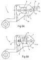
- the Axerarm 22 is so on the front 7 of the tape 1 launched that the intermediate leg 33 and the first leg 31 with her Narrow side on the front 7 rest. there the flap 38 projects into the aperture 6. Subsequently the Axerarm 22 is about a pivot axis 39th pivoted by the plant between the first Leg 31 and wall 17 is formed. The axer arm 22 is moved 90 ° about the pivot axis 39, that the second leg 32 from the image plane is pivoted outwards. Subsequently the Axerarm 22 is such that it is out of the picture plane protrudes, as indicated in Figure 6B. The first leg 31 thus engages through the opening 6, wherein the flap 38 adjacent to the back 8 of the support member 3 is located. The cloth 37 was during the pivoting action of the Axerarms 22 through moves through the section 11 of the opening 6, so that this lobe 37 adjacent to the back 8 of the support member 3 is located.
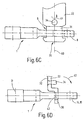
- FIG. 6C shows the band 1 and the axial arm 22 of FIG Figure 6B in side view.
- the first leg 31 has passed through the opening 6 is, so that the free end 35 of Axerarms 22 on the back 8 of the support member. 3 lies.
- the compound 44 also has a high stability on, as appropriate for all load directions Facilities are provided which prevent that the connection 44 is decoupled again.
- a relative rotation (arrow P in FIG. 7) of the Axerarms 22 with respect to the band 1 is thereby prevented that the first leg 31 on walls the breakthrough 6 is supported.
- connection 44 can thus a band 1 and an arm 2 for both right as well as left hinged sash be used.
- a band provided only for left or right battered Wing frame can be used. It can be provided that only one Bag 13 or 13 'at the opening 6 is provided. In addition, it is sufficient if a conically widening Recess 14 is provided, which the Support member 3 is not completely interspersed, so not designed as a breakthrough. Corresponding then the pin 34 can be made shorter on the Axerarm become.
Landscapes
- Engineering & Computer Science (AREA)
- Mechanical Engineering (AREA)
- Hinges (AREA)
- Pivots And Pivotal Connections (AREA)
- Buckles (AREA)
- Jib Cranes (AREA)
- Closing And Opening Devices For Wings, And Checks For Wings (AREA)
Claims (14)
- Liaison par couplage entre un compas et une charnière côté battant pour des fenêtres oscillobattantes, comportant :caractérisée en ce queune nervure coudée formée sur le compas et munie d'une première et d'une deuxième branche ainsi que d'une branche intermédiaire placée entre la première et la deuxième branche, etun passage formé sur la charnière et destiné à recevoir la branche intermédiaire, la première branche s'appuyant sur le côté arrière et la deuxième branche sur le côté avant d'une pièce de soutien munie du passage,
la pièce de soutien (3) s'étend transversalement, en particulier en angle droit par rapport à l'axe de rotation (D) de la charnière (1), la deuxième branche (32) de la nervure coudée (30) se trouve dans le plan (B) du compas (22),
une poche (13, 13') située dans le plan du côté avant ou du côté arrière (7, 8) est contiguë au passage (6) et au moins une partie de la première branche (31) y pénètre, et
la forme du contour périphérique du passage (6) et/ou de la poche (13, 13') correspond à la forme du contour périphérique de la première branche (31) et/ou de la branche intermédiaire (33). - Liaison par couplage selon la revendication 1,
caractérisée en ce que
la deuxième branche (32) forme une seule pièce avec le compas (22). - Liaison par couplage selon l'une des revendications précédentes,
caractérisée en ce que
un segment du compas (22) forme la deuxième branche (32). - Liaison par couplage selon l'une des revendications précédentes,
caractérisée en ce que
la nervure coudée (30) forme une seule pièce avec le compas (22). - Liaison par couplage selon l'une des revendications précédentes,
caractérisée en ce que
le compas (22) est une pièce en tôle estampée (23). - Liaison par couplage selon l'une des revendications précédentes,
caractérisée en ce que
la charnière (1) est une pièce coulée et/ou fraisée. - Liaison par couplage selon l'une des revendications précédentes,
caractérisée en ce que
un tenon (34) orienté en direction ou approximativement en direction de la branche intermédiaire (33) part de la deuxième branche (32). - Liaison par couplage selon l'une des revendications précédentes,
caractérisée en ce que
lorsqu'on les regarde depuis la deuxième branche (32), la branche intermédiaire (33) et le tenon (34) sont orientés dans la même direction. - Liaison par couplage selon l'une des revendications précédentes,
caractérisée en ce que
le tenon (34) a prise dans un creux (14), en particulier dans un passage (15) de la pièce de soutien (3). - Liaison par couplage selon l'une des revendications précédentes,
caractérisée en ce que
le tenon (34) est un tenon (34) dont le diamètre augmente vers l'extrémité libre (48). - Liaison par couplage selon l'une des revendications précédentes,
caractérisée en ce que
le creux (14) présente des parois (19 ; 20) coniques et adaptées au tenon (34) dont le diamètre augmente. - Liaison par couplage selon l'une des revendications précédentes,
caractérisée en ce que
pour une butée de droite à gauche, la charnière (1) y compris sa pièce de soutien (3) est symétrique par rapport à un plan central (E) perpendiculaire à l'axe de rotation (D) de la charnière (1). - Liaison par couplage selon l'une des revendications précédentes,
caractérisée en ce que
le passage (15) forme un double cône par rapport au plan central (E). - Liaison par couplage selon l'une des revendications précédentes,
caractérisée en ce que
l'extrémité libre (35) de la première branche (31) s'étend en forme de tête de marteau.
Applications Claiming Priority (2)
| Application Number | Priority Date | Filing Date | Title |
|---|---|---|---|
| DE19839410A DE19839410C1 (de) | 1998-08-29 | 1998-08-29 | Kuppelbare Verbindung zwischen Axerarm und flügelseitigem Band für Dreh-Kippfenster |
| DE19839410 | 1998-08-29 |
Publications (3)
| Publication Number | Publication Date |
|---|---|
| EP0984128A2 EP0984128A2 (fr) | 2000-03-08 |
| EP0984128A3 EP0984128A3 (fr) | 2001-10-24 |
| EP0984128B1 true EP0984128B1 (fr) | 2005-04-27 |
Family
ID=7879164
Family Applications (1)
| Application Number | Title | Priority Date | Filing Date |
|---|---|---|---|
| EP99115304A Expired - Lifetime EP0984128B1 (fr) | 1998-08-29 | 1999-08-03 | Dispositif de couplage entre un compas et une charnière du côté de l'aile pour fenêtre pivotante et basculante |
Country Status (3)
| Country | Link |
|---|---|
| EP (1) | EP0984128B1 (fr) |
| AT (1) | ATE294313T1 (fr) |
| DE (2) | DE19839410C1 (fr) |
Family Cites Families (5)
| Publication number | Priority date | Publication date | Assignee | Title |
|---|---|---|---|---|
| AT391734B (de) * | 1987-09-18 | 1990-11-26 | Mayer & Co Riegel Beschlag | Ausstellvorrichtung fuer den drehkippfluegel eines fensters oder einer tuer |
| DE4232945C2 (de) * | 1992-10-01 | 1996-03-21 | Siegenia Frank Kg | Scharnierbeschlag für Fenster, Türen od. dgl. |
| EP0600103B1 (fr) * | 1992-10-29 | 1994-10-05 | W. Hautau Gmbh | Pivot positionnable à droite ou à gauche pour dispositifs déflecteurs |
| DE19601326C2 (de) * | 1996-01-16 | 1999-03-11 | Jakob Escher Gmbh | Ausstellvorrichtung für Drehkippflügel |
| DE19623403C1 (de) * | 1996-06-12 | 1997-08-14 | Aubi Baubeschlaege Gmbh | Lösbare Verbindung für ein Kipp-, Kippschiebe- oder Kippschwenkfenster |
-
1998
- 1998-08-29 DE DE19839410A patent/DE19839410C1/de not_active Expired - Fee Related
-
1999
- 1999-08-03 AT AT99115304T patent/ATE294313T1/de active
- 1999-08-03 EP EP99115304A patent/EP0984128B1/fr not_active Expired - Lifetime
- 1999-08-03 DE DE59911971T patent/DE59911971D1/de not_active Expired - Lifetime
Also Published As
| Publication number | Publication date |
|---|---|
| DE59911971D1 (de) | 2005-06-02 |
| EP0984128A3 (fr) | 2001-10-24 |
| ATE294313T1 (de) | 2005-05-15 |
| DE19839410C1 (de) | 2000-01-13 |
| EP0984128A2 (fr) | 2000-03-08 |
Similar Documents
| Publication | Publication Date | Title |
|---|---|---|
| EP0702123B1 (fr) | Charnière de porte à arrêtoir de porte intégré pour portes de véhicules, l'arrêtoir comprenant une barre de torsion et élément d'arrêt | |
| AT401797B (de) | Eingelenk-möbelscharnier | |
| DE3408202C2 (de) | Federscharnier zwischen zwei Teilen einer Brille | |
| DE602004011617T2 (de) | Einbauscharnier um brillenbügel elastisch zu machen | |
| AT403717B (de) | Scharnier mit quetschschutzvorrichtung | |
| WO1993021413A1 (fr) | Charniere de meuble | |
| DE102010004772B3 (de) | Türband für Aluminiumtüren | |
| DE3405343C2 (fr) | ||
| EP0979751B1 (fr) | Monture de support de siège de véhicule avec un support pivotable gauche et droit | |
| DE69631910T2 (de) | Einstellbarer adapter für eine unterschenkelprothese | |
| EP0033877A1 (fr) | Fenêtre ou porte | |
| DE3033713C2 (fr) | ||
| DE2816635C3 (de) | Scharniertopf für ein Möbeltürscharnier | |
| DE19839410C1 (de) | Kuppelbare Verbindung zwischen Axerarm und flügelseitigem Band für Dreh-Kippfenster | |
| EP0989273B1 (fr) | Charnière avec centre de rotation mobile | |
| DE69611198T2 (de) | Scharniervorrichtung insbesondere für die Tür eines elektrischen Haushaltgerätes oder dergleichen | |
| DE2131852C3 (de) | Klappenscharnier | |
| DE112021003269T5 (de) | Gestänge- und Scharnieranordnung mit mehreren hochbelastbaren Verstrebungen für schwenkbar gelagerte Ausstellfenster | |
| DE4021779B4 (de) | Sicherungsschere | |
| DE4339797C1 (de) | Aushängbares 180 DEG -Scharnier | |
| DE2029843C3 (de) | Möbelscharnier | |
| EP0995867B1 (fr) | Armoire de distribution électrique avec dispositif de fermeture à barre | |
| DE29603490U1 (de) | Kastenaufbau eines Nutzfahrzeugs mit wenigstens einer schwenkbar angelenkten Tür | |
| EP1747338B1 (fr) | Ferrure de charniere pour une porte de vehicule a moteur | |
| EP0671531B1 (fr) | Charnière |
Legal Events
| Date | Code | Title | Description |
|---|---|---|---|
| PUAI | Public reference made under article 153(3) epc to a published international application that has entered the european phase |
Free format text: ORIGINAL CODE: 0009012 |
|
| AK | Designated contracting states |
Kind code of ref document: A2 Designated state(s): AT BE CH CY DE DK ES FI FR GB GR IE IT LI LU MC NL PT SE Kind code of ref document: A2 Designated state(s): AT BE CH DE FR IT LI |
|
| AX | Request for extension of the european patent |
Free format text: AL;LT;LV;MK;RO;SI |
|
| PUAL | Search report despatched |
Free format text: ORIGINAL CODE: 0009013 |
|
| AK | Designated contracting states |
Kind code of ref document: A3 Designated state(s): AT BE CH CY DE DK ES FI FR GB GR IE IT LI LU MC NL PT SE |
|
| AX | Request for extension of the european patent |
Free format text: AL;LT;LV;MK;RO;SI |
|
| 17P | Request for examination filed |
Effective date: 20020225 |
|
| AKX | Designation fees paid |
Free format text: AT BE CH DE FR IT LI |
|
| GRAP | Despatch of communication of intention to grant a patent |
Free format text: ORIGINAL CODE: EPIDOSNIGR1 |
|
| GRAS | Grant fee paid |
Free format text: ORIGINAL CODE: EPIDOSNIGR3 |
|
| GRAA | (expected) grant |
Free format text: ORIGINAL CODE: 0009210 |
|
| AK | Designated contracting states |
Kind code of ref document: B1 Designated state(s): AT BE CH DE FR IT LI |
|
| REG | Reference to a national code |
Ref country code: CH Ref legal event code: EP |
|
| REG | Reference to a national code |
Ref country code: CH Ref legal event code: NV Representative=s name: E. BLUM & CO. PATENTANWAELTE |
|
| REF | Corresponds to: |
Ref document number: 59911971 Country of ref document: DE Date of ref document: 20050602 Kind code of ref document: P |
|
| ET | Fr: translation filed | ||
| PLBE | No opposition filed within time limit |
Free format text: ORIGINAL CODE: 0009261 |
|
| STAA | Information on the status of an ep patent application or granted ep patent |
Free format text: STATUS: NO OPPOSITION FILED WITHIN TIME LIMIT |
|
| 26N | No opposition filed |
Effective date: 20060130 |
|
| REG | Reference to a national code |
Ref country code: CH Ref legal event code: PFA Owner name: ROTO FRANK AG Free format text: ROTO FRANK AG#STUTTGARTER STRASSE 145-149#70771 LEINFELDEN-ECHTERDINGEN (DE) -TRANSFER TO- ROTO FRANK AG#STUTTGARTER STRASSE 145-149#70771 LEINFELDEN-ECHTERDINGEN (DE) |
|
| PGFP | Annual fee paid to national office [announced via postgrant information from national office to epo] |
Ref country code: CH Payment date: 20130826 Year of fee payment: 15 Ref country code: AT Payment date: 20130821 Year of fee payment: 15 Ref country code: DE Payment date: 20130823 Year of fee payment: 15 |
|
| PGFP | Annual fee paid to national office [announced via postgrant information from national office to epo] |
Ref country code: FR Payment date: 20130820 Year of fee payment: 15 |
|
| PGFP | Annual fee paid to national office [announced via postgrant information from national office to epo] |
Ref country code: IT Payment date: 20130823 Year of fee payment: 15 |
|
| PGFP | Annual fee paid to national office [announced via postgrant information from national office to epo] |
Ref country code: BE Payment date: 20130821 Year of fee payment: 15 |
|
| REG | Reference to a national code |
Ref country code: DE Ref legal event code: R119 Ref document number: 59911971 Country of ref document: DE |
|
| REG | Reference to a national code |
Ref country code: CH Ref legal event code: PL |
|
| REG | Reference to a national code |
Ref country code: AT Ref legal event code: MM01 Ref document number: 294313 Country of ref document: AT Kind code of ref document: T Effective date: 20140803 |
|
| PG25 | Lapsed in a contracting state [announced via postgrant information from national office to epo] |
Ref country code: CH Free format text: LAPSE BECAUSE OF NON-PAYMENT OF DUE FEES Effective date: 20140831 Ref country code: BE Free format text: LAPSE BECAUSE OF NON-PAYMENT OF DUE FEES Effective date: 20140831 Ref country code: LI Free format text: LAPSE BECAUSE OF NON-PAYMENT OF DUE FEES Effective date: 20140831 Ref country code: IT Free format text: LAPSE BECAUSE OF NON-PAYMENT OF DUE FEES Effective date: 20140803 |
|
| REG | Reference to a national code |
Ref country code: DE Ref legal event code: R119 Ref document number: 59911971 Country of ref document: DE Effective date: 20150303 |
|
| PG25 | Lapsed in a contracting state [announced via postgrant information from national office to epo] |
Ref country code: AT Free format text: LAPSE BECAUSE OF NON-PAYMENT OF DUE FEES Effective date: 20140803 |
|
| REG | Reference to a national code |
Ref country code: FR Ref legal event code: ST Effective date: 20150430 |
|
| PG25 | Lapsed in a contracting state [announced via postgrant information from national office to epo] |
Ref country code: DE Free format text: LAPSE BECAUSE OF NON-PAYMENT OF DUE FEES Effective date: 20150303 |
|
| PG25 | Lapsed in a contracting state [announced via postgrant information from national office to epo] |
Ref country code: FR Free format text: LAPSE BECAUSE OF NON-PAYMENT OF DUE FEES Effective date: 20140901 |