EP0984131B1 - Système d'ombrage et de déflexion de lumière - Google Patents
Système d'ombrage et de déflexion de lumière Download PDFInfo
- Publication number
- EP0984131B1 EP0984131B1 EP99117021A EP99117021A EP0984131B1 EP 0984131 B1 EP0984131 B1 EP 0984131B1 EP 99117021 A EP99117021 A EP 99117021A EP 99117021 A EP99117021 A EP 99117021A EP 0984131 B1 EP0984131 B1 EP 0984131B1
- Authority
- EP
- European Patent Office
- Prior art keywords
- light
- shading
- directing
- support
- slats
- Prior art date
- Legal status (The legal status is an assumption and is not a legal conclusion. Google has not performed a legal analysis and makes no representation as to the accuracy of the status listed.)
- Expired - Lifetime
Links
Images
Classifications
-
- E—FIXED CONSTRUCTIONS
- E06—DOORS, WINDOWS, SHUTTERS, OR ROLLER BLINDS IN GENERAL; LADDERS
- E06B—FIXED OR MOVABLE CLOSURES FOR OPENINGS IN BUILDINGS, VEHICLES, FENCES OR LIKE ENCLOSURES IN GENERAL, e.g. DOORS, WINDOWS, BLINDS, GATES
- E06B9/00—Screening or protective devices for wall or similar openings, with or without operating or securing mechanisms; Closures of similar construction
- E06B9/24—Screens or other constructions affording protection against light, especially against sunshine; Similar screens for privacy or appearance; Slat blinds
-
- E—FIXED CONSTRUCTIONS
- E06—DOORS, WINDOWS, SHUTTERS, OR ROLLER BLINDS IN GENERAL; LADDERS
- E06B—FIXED OR MOVABLE CLOSURES FOR OPENINGS IN BUILDINGS, VEHICLES, FENCES OR LIKE ENCLOSURES IN GENERAL, e.g. DOORS, WINDOWS, BLINDS, GATES
- E06B3/00—Window sashes, door leaves, or like elements for closing wall or like openings; Layout of fixed or moving closures, e.g. windows in wall or like openings; Features of rigidly-mounted outer frames relating to the mounting of wing frames
- E06B3/66—Units comprising two or more parallel glass or like panes permanently secured together
- E06B3/6604—Units comprising two or more parallel glass or like panes permanently secured together comprising false glazing bars or similar decorations between the panes
-
- E—FIXED CONSTRUCTIONS
- E06—DOORS, WINDOWS, SHUTTERS, OR ROLLER BLINDS IN GENERAL; LADDERS
- E06B—FIXED OR MOVABLE CLOSURES FOR OPENINGS IN BUILDINGS, VEHICLES, FENCES OR LIKE ENCLOSURES IN GENERAL, e.g. DOORS, WINDOWS, BLINDS, GATES
- E06B9/00—Screening or protective devices for wall or similar openings, with or without operating or securing mechanisms; Closures of similar construction
- E06B9/24—Screens or other constructions affording protection against light, especially against sunshine; Similar screens for privacy or appearance; Slat blinds
- E06B9/26—Lamellar or like blinds, e.g. venetian blinds
- E06B9/264—Combinations of lamellar blinds with roller shutters, screen windows, windows, or double panes; Lamellar blinds with special devices
Definitions
- the invention relates to a shading and light control system according to the Preamble of claim 1.
- Glazing systems are increasingly being used in construction and facade technology, which perform demanding tasks beyond the pure glazing function Take over the lighting (and partly also the air conditioning) of a building.
- lighting a central concern of such systems is that To reject natural sunlight on the one hand (sun protection) and on the other hand in to redirect the interior of the building and use it there for lighting (light control).
- prism plates were used for sun protection, which has a smooth outer surface and an underlying sawtooth Have surface.
- the direct sunlight falls at an angle that it can penetrate the smooth surface. Underneath it hits a lot shallow angle on a surface of the sawtooth that it cannot overcome because it suffers total reflection from her. This way at least the majority of the directly incident light is rejected and does not get into the building.
- flexible installation with sun tracking should be provided. With fixed Installation can cause unwanted light passage by mirroring the Bottom can be avoided.
- the diffuse light coming in from all directions is able to overcome the prismatic plates and is led into the building and occurs essentially in the horizontal direction. It can be either other light-directing elements are directed towards the ceiling redirect the room.
- light control glasses have become known with which are exposed to direct sunlight through built-in reflectors on the ceiling Redirect space and thus can be used for lighting.
- the reflectors are located between two panes of glass and are therefore protected from contamination protected.
- the light is deflected via total reflection.
- Lightshelfs have also become known for controlling light. It is understood as highly reflective curved surfaces arranged horizontally in front of the glazing, due to the direct sunlight entering at different angles Direction of a room on the ceiling is redirected.
- the aforementioned light directing systems do indeed allow the direct to be deflected incoming sunlight, but no sun protection.
- the publication DE 196 03 638 A1 discloses a glass element with an integrated store (Slatted blind).
- the glass element comprises at least two glass plates, which are parallel to each other and spaced from each other, one between the glass plates peripheral first spacer, which consists of a horizontal lower Section and two vertical side sections and with the glass plates is sealingly connected and together with these a first air gap includes.
- the glass element comprises a store designed as an elongated unit, which in its upper part between the glass plates and between the two upper ones Ends of the side sections is arranged horizontally.
- the side Sections point at a distance from their top end that is the height of the store corresponds to an inwardly projecting paragraph on which the store with their lateral ends.
- the first air gap is used to equalize the pressure connected to the outside via means for drying the air and is above the Store closed with a vapor barrier.
- a third glass plate is arranged behind the second glass plate, which is replaced by a second Spacer is kept at a distance.
- fixed light directing elements can be arranged in the second air gap.
- EP 786 623 A1 discloses a device for supplying a room with glare-free and diffuse sunlight.
- a stack of Light guiding elements built into the skylight of a window.
- the light directing elements are in such a way that incoming sun rays in a central part and in an end part of the Light directing elements are totally reflected several times and thereby scattered and in Exit radiation prisms.
- the publication DE 197 28 391 A1 discloses light guide plates made of transparent Plastics such as polycarbonate or polymethacrylate. They are manufactured by Insert several thin strips of plastic B into a transparent one Plastic A, with the proviso that A and B are incompatible and the tapes from the Plastic B can then be pulled out. The resulting voids in the Plastic A plates are used to redirect light. It is the object of the invention to provide a glazing system with that with simple glazing means and without complex Mechanics such as Sun tracking both a protection from the direct incident sunlight as well as directing light into the interior of a room Lighting purposes is possible.
- a shading and light control system has two Slices on between which both a conventional slatted blind and a light control system with rigid reflectors are arranged.
- the slatted blind has pivotable about its longitudinal axis and optionally also lifting and lowerable slats and allows optional shading of the inside of a Space.
- the slatted blind is combined with one between the Discs arranged light-guiding device, the one running between the panes has rigid reflectors that allow sunlight to pass through Total reflection can be conducted into the interior of a room and used as diffuse light Room lighting is usable.
- the invention is based on the idea that by combining two technically less complex systems - namely a conventional slatted blind and a light control device with rigid reflectors - get a system which meets the practical needs in relation to shading and light control in most cases. Because the reflectors are rigid are executed, there is no need for any complex mechanics for sun tracking is required. Only the slats of the slatted blind are designed to be movable, so this is the only point where mechanical effort is involved. According to the invention, the slats can be pivoted and optionally additionally lifted. and lowerable.
- the reflectors of almost all light directing devices produce at not too low Part of the emitted light (i.e. a beam of light) in one Direction that is steeper than the horizontal, i.e. this light is on the ceiling headed. It is particularly valuable for room lighting because it is from the ceiling is reflected diffusely. To use this light beam effectively, one is . preferred embodiment of the invention, the light directing device above the Slatted blind arranged.
- the light control device has the function of a Skylights and generates the directed light in a place where it is special is desired, namely near the ceiling.
- the height of the light directing device is preferably not measured too big because then the falling club over the heads of those in the room working people is led away.
- the invention is therefore not the light control device installed as a skylight greater than 40 cm, with a range of 30 to 40 cm being preferred.
- Use steering devices designed according to the invention, between two Panes can be installed, the essential functional properties such systems have already been described above.
- a light-guiding system in the form of a disk is preferred at the moment Acrylic glass, in which (produced for example by extrusion technology) horizontally running reflectors are incorporated.
- the horizontal reflectors have that Shape of flat, band-shaped and substantially perpendicular to the plane of the Disc-arranged cavities, the height of which is approximately 0.8 mm.
- Such a light control system is marketed under the product name "Plexiglas® Daylight "from Röhm GmbH, Darmstadt.
- the company innovative Glassysteme GmbH & Co. KG, Friedrichshafen sells the material under the Product name "Inglas-Y®” in a form in which the acrylic glass pane is placed between two float glass panes.
- Inglas-Y® has a thickness of 8 mm depending on the thickness of the float glass (2 or 3.5 mm) Material thicknesses of 12 or 15 mm.
- polycarbonate glass In addition to acrylic glass, polycarbonate glass can also be used.
- a suitable slatted blind e.g. the German patent specification DE 39 04 763 C2.
- This slatted blind (hereinafter referred to as the inventor "Torresan blind") is detailed later in this application described.
- the slatted blind is of four Surround spacers that are glued to the panes and a gas-tight closed frame made of two horizontal trusses and two vertical ones Form posts. It has a support that is screwed to the upper crossbar is and with means for pivoting and optionally also lifting and lowering the Slats is provided. These means include a winding / turning shaft with a drive device provided in the carrier is detachably coupled.
- One of vertical post has a height that is about the height of the beam is less than the height of the other post.
- the wearer wears his Post with a lower height corresponding to a bearing support for one Coupling element with the drive device, which is complementary to the bearing shaped and releasably inserted into this and the less Height of the post essentially fills free space.
- gas-tight is intended to refer both to normal atmospheric air and to protective gases which are used in glazing technology for heat and / or sound insulation.
- protective gases are noble gases such as argon (Ar), krypton (Kr) and xenon (Xe) as well as sulfur hexafluoride (SF 6 ). This also applies in connection with the gas-tight gearboxes mentioned below.
- the Torresan Venetian blind is a means equipped with which the slats are pivoted, but only can also be optionally raised and lowered.
- a drive can Electric motor or a manually operated device can be used.
- a An embodiment of such a device is one with a manually operated cable pull rotatable drive wheel, which outside of the four spacers formed frame arranged at the height of the shorter post and - optionally with the interposition of an airtight transmission - with a shaft with the Coupling element is connected.
- the drive device can also be a be manually operated crank device, which in a corresponding manner outside the Frame is arranged and their rotational movement - optionally with the interposition a universal joint and / or an airtight gearbox the coupling element is transferable.
- the drive device be a manually operated knob that is outside the scope of the Spacer is arranged and its rotational movement with interposition of helical gearboxes and optionally an airtight operation on the Coupling element is transferable.
- Systems control the light with rigid reflectors, which is the most striking Light when the sun is high (i.e. during the summer months and during Midday in the winter months) due to the rising light club relatively steep Steer ceiling of a room in a building.
- the light comes from the ceiling reflects, which leads to a brightening of the room depth, which reaches without glare becomes.
- the area occupied by the slatted blind can be turned (and optionally also lowering or raising) the slats additionally one Shading and thus sun protection can be achieved.
- the slats of the Slatted blind swiveled in a controlled manner and optionally additionally can be raised and lowered so that shading in the desired Extent sets and a too high room temperature is avoided.
- the energy saving achieved and the amount at Environmental protection is huge because air conditioning systems are now so widespread and used that - especially in office buildings - electricity consumption for air conditioning far exceeds that for lighting and heating.
- the light control device Sunlight directed into the room is somewhat flatter, but can also can be used to illuminate the room.
- the slatted blind is used in these Conditions preferably set so that shading is reduced (by Place the slats in a horizontal direction or additionally by lifting the Slats and raising of the slat package). Artificial light is then switched on if the lighting achieved by the light control device is not is more sufficient. This can also be done automatically using the above intelligent controls.
- the shading and light control system according to the invention performs also an important contribution to compliance with legal regulations, that exist in relation to the illumination of workplaces.
- legal regulations that exist in relation to the illumination of workplaces.
- the Occupational Health and Safety Act the VDU Ordinance
- the workplace regulation the DIN 5035.
- Another advantage of the invention is the arrangement of both the light steering device as well as the slatted blind between two panes. This protects both from contamination, thus ensuring trouble-free and maintenance-free Operation and therefore represents a significant advantage over facilities glazing systems, e.g. Lightshelfs.
- the shading and light control system according to the invention ready-to-install unit.
- Such a unit is unique - by design - Less expensive because they use standardized building elements enabled in larger numbers. Because the light control device and the Slat blinds are assembled together, there is also an assembly step saved, and there is a reduction in installation costs.
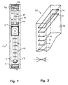
- Fig. 1 shows a schematic representation of an embodiment of an inventive Shading and light control system 1 in section (briefly below “System”).
- the slatted blind 12 and the light directing device 30 are shown, which are arranged between two disks 2.
- the slatted blind 12 is through a spacer 4 summarized, which consists of four pieces that a closed Form a frame (for details see Fig. 3). Another spacer 4a runs along the upper edges of the panes 2, 3 and limits and stabilizes this System.
- the light control device 30 consists of a vertically installed Disc 32 made of acrylic glass, in which reflectors 31 are incorporated (details see Fig. 2).
- the light control device 30 is made in pairs Spacers 4b, which run on both sides of the acrylic glass pane 32. Instead of A spacer can also be used in pairs, in which the Acrylic glass pane 32 is placed and is thus fixed. 1 is also shown a seal 33 which extends around all four sides of the panes 2, 3 and that System seals gas-tight.
- FIG 2 shows a perspective view of the light control device 30 Plexiglas® Daylight. It is made of an acrylic glass pane 32 with a thickness of 8 mm constructed, in the reflectors 31 are incorporated. For simplified illustration 2, only two reflectors 31 are completely drawn in FIG However, details apply to everyone.
- the reflectors 31 run horizontally and have the shape of flat, ribbon-shaped cavities, the height of which is 0.8 mm is. They run parallel to each other at regular intervals and parallel to top and bottom of the acrylic glass pane 32 over its entire width, so that at the given slice thickness and given distance there is a ray path of sunlight with total reflection.
- the reflectors 31 are perpendicular to Level of the acrylic glass pane 32, i.e. the level of the band-shaped Cavities lie in the vertical on the acrylic glass pane 32 (in the vertical Installation of the acrylic glass pane 32, this is also the horizontal).
- the drawing shows the angular range around which the cavities follow front or back (i.e. viewed in cross-section clockwise or counter-clockwise Clockwise) can be inclined against this vertical. This angle is about 5 to 15 °.
- FIGS. 1 and 2 also shows a light directing device 30, in which the acrylic glass pane 32 - unlike the product mentioned Inglas-Y® - is not placed between two float glass panes.
- a light directing device 30 in which the acrylic glass pane 32 - unlike the product mentioned Inglas-Y® - is not placed between two float glass panes.
- Such an embodiment is sometimes preferred for weight reasons, for example, because that System will not become too heavy. If there are no such reasons, they can Float glass panes are additionally used, and Figs. 1 and 2 are corresponding to complete.
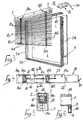
- Fig. 3 shows an exploded view of a Torresan slat blind 12. Die illustrated embodiment allows both a pivoting and a Raise and lower the slats. It has a first disc 2 and a second Disc 3 made of glass through the spacer 4 arranged therebetween are held in parallel planes.
- the spacer 4 has two vertical posts 5a and 5b and two horizontal cross members 6a and 6b.
- the post 5b has a lower height than the post 5a, by one Amount which is equal to the height of a carrier 7, which consists of a box-shaped Element is formed with a substantially rectangular cross section.
- the posts 5a, 5b and the crossbeams 6a, 6b of the spacer 4 one or more inner, longitudinal channels 8 having engagement seats for coupling means; these are e.g. with the Carrier 7 firmly connected and consist of complementary teeth 9, which vertically and facing outwards on this support 7 in association with Stand up post 5b.
- the carrier 7 shown in Fig. 4 is connected to the cross member 6b and has the side facing away from the teeth 9 two receiving bores 10 for fastening screws.
- the carrier 7 also has on the side on which the bores 10 are arranged, a plurality of openings 11a, 11b and 11c, which are used for visual inspection of means arranged in this carrier 7 for pivoting and lifting and lowering the slat curtain of the slat blind 12 are determined.
- the Louvre blind 12 has a plurality of slats 13 which are used of two side turning cords 14a and 14b for pivoting the Slats 13 are kept parallel to each other and by means of a pair of cables 15a and 15b can be contracted (lifting and lowering).
- the carrier 7 also has at its end above the channels 8 of the post 5b a bearing holder for a coupling element with the drive of the Louver blind 12 on (see Fig. 3).
- the coupling element is in the present Case formed by the housing 21. It has the shape of a cuboid (i.e. is complementary to the inventory) and takes a drive Electric motor and supports it in a rotationally fixed manner.
- the housing 21 fills the the lower height of the post 5b essentially creates free space.
- the axis 22 of the electric motor is hexagonal in shape with the end 23 Shaft 17 can be coupled.
- the slatted blind 12 is by gluing the first pane 2 and the second Washer 3 formed with the spacer 4, the spacer 4 so is designed so that the electrical cable 24 of the motor in the region of the end of the Post 5b, which is adjacent to the crossbeam 6b, can emerge.
- This Cable 24 is received in a seat cut into the window and with the interposition of a certain switch with a power source connected.
- the slat blind 12 is used as follows. First is the Assembly, i.e. the carrier 7 is with the cross member 6b and the post 5b connected and the housing 21 inserted into the carrier 7, the axis 22 of the Motor is coupled to the end 23 of the shaft 17. Now it just has to Electric motor can be switched to the desired orientation and / or one To raise the blind. A rotation of the axis 22 of the motor in One or the other direction initially causes drag due to friction through the first rope pulley 19 and the second rope pulley 20 the lateral turning cords 14a and 14b are subjected to a slight pull which is sufficient the slats 13 to incline in one direction or the other. The further one Actuation of the motor in the direction of rotation leads to partial or complete winding of the ropes 15a and 15b and consequently for starting up and / or lowering the slats 13.
- the slatted blind 12 allows the setting of an effective one and selectable sun protection by quickly and easily removing the slats 13 adjusted and / or within that between the first disc 2 and the second Disk 3 existing air gap raises or lowers. This can be done perform very conveniently, simply by pressing a switch that starts the electric motor. Since the slats 13 are raised completely can, a window equipped with the Venetian blind 12 also completely without Darkening can be used.
- the slatted blind 12 can be extremely easy to maintain because it can be exchanged Electric motor, the housing 21 can be removed in a simple manner.
Landscapes
- Engineering & Computer Science (AREA)
- Structural Engineering (AREA)
- Civil Engineering (AREA)
- Architecture (AREA)
- Blinds (AREA)
- Non-Portable Lighting Devices Or Systems Thereof (AREA)
- Glass Compositions (AREA)
- Circuit Arrangement For Electric Light Sources In General (AREA)
Claims (12)
- Système d'ombrage et de déflexion de lumière (1) avec deux plaques (2, 3), présentant une jalousie (12) avec des lamelles (13) pivotant autour de l'axe longitudinal de cette dernière et pouvant être sélectivement relevées et abaissées en supplément, jalousie par laquelle l'intérieur d'un local peut être sélectivement ombragé, et présentant un dispositif de déflexion de lumière (30) avec des réflecteurs rigides (31), par lesquels la lumière solaire incidente peut être dirigée par réflexion totale à l'intérieur d'un local et être utilisée sous forme de lumière diffuse pour l'éclairage du local, la jalousie (12) et le dispositif de déflexion de lumière (30) étant disposés entre les deux plaques (2, 3) et les réflecteurs rigides (31) du dispositif de déflexion de lumière (30) s'étendant entre ces plaques (2, 3), le dispositif de déflexion de lumière (30) étant disposé au-dessus de la jalousie (12) et un scellement (33) étant prévu, qui s'étend à l'extérieur autour des quatre côtés des deux plaques (2, 3) et qui ferme de façon étanche aux gaz le système d'ombrage et de déflexion de lumière (1).
- Système d'ombrage et de déflexion de lumière suivant la revendication 1, caractérisé en ce que le dispositif de déflexion de lumière (30) a une hauteur dans une plage allant jusqu'à 40 cm, de préférence de 30 à 40 cm.
- Système d'ombrage et de déflexion de lumière suivant l'une des revendications précédentes, caractérisé en ce que les réflecteurs sont formés par des espaces creux (31) plats et en forme de bandes, s'étendant horizontalement dans le dispositif de déflexion de lumière (30), à distances régulières, parallèlement entre eux et parallèlement au bord supérieur et/ou inférieur d'une plaque en verre acrylique (32), espaces creux dont le plan est essentiellement perpendiculaire à la plaque de verre acrylique (32) ou est incliné d'un angle de 5 à 15° par rapport à la perpendiculaire dans le sens des aiguilles d'une montre ou dans le sens inverse à celui des aiguilles d'une montre.
- Système d'ombrage et de déflexion de lumière suivant la revendication 1, caractérisé en ce que le dispositif de déflexion de lumière (30) est formé de verre acrylique ou de verre de polycarbonate, de préférence de verre de polyméthacrylate de méthyle.
- Système d'ombrage et de déflexion de lumière suivant l'une des revendications précédentes, caractérisé en ce que la jalousie (12) est entourée par quatre écarteurs (4), qui sont collés au plaques (2, 3) et forment un cadre fermé sélectivement de façon étanche à l'air, composé de deux traverses horizontales (6a, 6b) et de deux montants verticaux (5a, 5b), en ce que la jalousie (12) présente un support (7), assemblé fixement avec la traverse supérieure (6b) et muni de moyens pour le pivotement et sélectivement pour le relèvement et l'abaissement des lamelles (13) également, les moyens présentant un axe d'enroulement/renversement (17), accouplé de façon amovible avec un dispositif d'entraínement prévu dans le support (7), en ce qu'un montant (5b) présente une hauteur inférieure d'à peu près la hauteur du support (7) à la hauteur de l'autre montant (5a), et en ce que le support (7) présente sur son extrémité correspondante au montant (5b) de hauteur inférieure un logement de palier pour un élément d'accouplement avec le dispositif d'entraínement, élément de forme complémentaire au logement de palier, mis en place de façon amovible dans ce dernier, et remplissant essentiellement l'espace libre formé par la hauteur inférieure du montant (5b).
- Système d'ombrage et de déflexion de lumière suivant la revendication 5, caractérisé en ce que les montants (5a, 5b) ont un ou plusieurs canaux (8) intérieurs s'étendant dans le sens longitudinal, des dents (9) de forme complémentaire au ou aux canaux (8) s'engageant dans le ou dans les canaux (8) du montant (5b) de hauteur inférieure, ces dents étant assemblées fixement avec le support (7) sur son extrémité correspondante au montant vertical (5b) de hauteur inférieure et dépassant à angle droit du support (7) vers l'extérieur.
- Système d'ombrage et de déflexion de lumière suivant la revendication 6, caractérisé en ce que le support (7) est formé d'un élément en forme de caisson essentiellement rectangulaire en projection horizontale, qui présente sur le côté opposé aux dents (9) un ou plusieurs trous de réception (10) pour des vis de fixation, par l'intermédiaire desquelles le support (7) est vissé avec la traverse supérieure (6b).
- Système d'ombrage et de déflexion de lumière suivant l'une des revendications 5 à 7, caractérisé en ce que l'axe d'enroulement/renversement (17) hexagonal, vissé à l'intérieur du support (7), est monté en rotation dans au moins deux épaulements de palier (16a, 16b) logés dans le support (7), en ce qu'au moins une première poulie (19) et une seconde poulie (20) sont coincées sur l'axe d'enroulement/renversement (17), ces poulies supportant à chaque fois un cordon de renversement (14a, 14b) qui entoure latéralement les lamelles (13) et est assemblé avec ces dernières pour leur pivotement, les extrémités de deux câbles (15a, 15b), qui s'étendent au travers d'ouvertures (18a, 18b) découpées dans le support (7) et servent à relever et à abaisser les lamelles (13), étant en supplément assemblées sélectivement avec la première et la seconde poulie (19, 20).
- Système d'ombrage et de déflexion de lumière suivant l'une des revendications 5 à 8, caractérisé en ce que l'élément d'accouplement est le carter (21) d'un moteur électrique logé dans le logement de palier.
- Système d'ombrage et de déflexion de lumière suivant l'une des revendications 5 à 8, caractérisé en ce que le dispositif d'entraínement est une roue de commande tournant avec un câble de transmission actionné à la main, la roue de commande étant disposée à l'extérieur du cadre formé par les quatre écarteurs (4) au niveau du montant (5b) le plus court et - sélectivement en intercalant une transmission étanche au gaz - étant assemblée par un arbre avec l'élément d'accouplement.
- Système d'ombrage et de déflexion de lumière suivant l'une des revendications 5 à 8, caractérisé en ce que le dispositif d'entraínement est un mécanisme à manivelle actionné à la main, qui est disposé à l'extérieur du cadre formé par les quatre écarteurs (4) et dont le mouvement de rotation - sélectivement en intercalant un joint de Cardan et/ou en supplément une transmission étanche aux gaz - est transmissible à l'élément d'accouplement.
- Système d'ombrage et de déflexion de lumière suivant l'une des revendications 5 à 8, sous réserve que le support (7) soit muni de moyens pour le seul pivotement des lamelles (13) et qu'aucun câble (15a, 15b) ne soit prévu pour le relèvement et l'abaissement des lamelles, caractérisé en ce que le dispositif d'entraínement est un bouton rotatif actionné à la main, qui est disposé à l'extérieur du cadre formé par les quatre écarteurs (4) et dont le mouvement de rotation est transmissible à l'élément d'accouplement en intercalant des engrenages droits et en supplément une transmission sélective étanche aux gaz.
Applications Claiming Priority (2)
| Application Number | Priority Date | Filing Date | Title |
|---|---|---|---|
| DE29815654U | 1998-08-31 | ||
| DE29815654U DE29815654U1 (de) | 1998-08-31 | 1998-08-31 | Beschattungs- und Lichtlenksystem |
Publications (2)
| Publication Number | Publication Date |
|---|---|
| EP0984131A1 EP0984131A1 (fr) | 2000-03-08 |
| EP0984131B1 true EP0984131B1 (fr) | 2001-11-28 |
Family
ID=8062054
Family Applications (1)
| Application Number | Title | Priority Date | Filing Date |
|---|---|---|---|
| EP99117021A Expired - Lifetime EP0984131B1 (fr) | 1998-08-31 | 1999-08-30 | Système d'ombrage et de déflexion de lumière |
Country Status (3)
| Country | Link |
|---|---|
| EP (1) | EP0984131B1 (fr) |
| AT (1) | ATE209748T1 (fr) |
| DE (2) | DE29815654U1 (fr) |
Families Citing this family (6)
| Publication number | Priority date | Publication date | Assignee | Title |
|---|---|---|---|---|
| FR2804161B1 (fr) | 2000-01-26 | 2002-07-26 | Saint Gobain Vitrage | Vitrage isolant a double store integre |
| DE102006053212A1 (de) * | 2006-11-11 | 2008-05-29 | Hydro Building Systems Gmbh | Ausfachungselement für Fenster, Türen, Trennwände, Fassaden und dgl. |
| DE102008013640B4 (de) | 2008-03-11 | 2012-01-19 | Faltenbacher Jalousienbau Gmbh & Co. Kg | Eckverbinder zum Verbinden von Hohlprofil-Rahmenteilen zur Abstandshalterung von Isolierglasscheiben sowie Isolierglasfenster |
| DE202008003461U1 (de) | 2008-03-11 | 2009-07-30 | Faltenbacher Jalousienbau Gmbh & Co. Kg | Eckverbinder zum Verbinden von Hohlprofil-Rahmenteilen zur Abstandshalterung von Isolierglasscheiben sowie Isolierglasfenster |
| EP2626496A1 (fr) | 2012-02-10 | 2013-08-14 | Technoform Glass Insulation Holding GmbH | Profil d'espaceur pour cadre d'espaceur pour une unité de verre isolant avec éléments d'intervalle et unité de verre isolant |
| CN107724937A (zh) * | 2017-09-28 | 2018-02-23 | 苏州见真物联科技有限公司 | 一种自动百叶窗 |
Family Cites Families (13)
| Publication number | Priority date | Publication date | Assignee | Title |
|---|---|---|---|---|
| DE1683284U (de) | 1952-04-07 | 1954-09-16 | Erhardt & Leimer O H G | Automatische breiteneinstell-vorrichtung fuer gewebebahn fuehrer. |
| DE1686391U (de) | 1953-02-23 | 1954-11-04 | Hedwig Gaa | Jalousie, insbesondere fuer den einbau in den scheibenzwischenraum von verbundfenstern. |
| US3795267A (en) * | 1970-01-28 | 1974-03-05 | Levolor Lorentzen Inc | Venetian blind |
| DE2615379A1 (de) | 1976-04-08 | 1977-10-27 | Christian Bartenbach | Abschirmung fuer lichtoeffnungen, fenster und dergleichen |
| GB2162226B (en) | 1984-07-25 | 1988-01-13 | Tachikawa Blind Mfg | Venetian blind |
| IT1220822B (it) | 1988-04-13 | 1990-06-21 | Adriano Torresan | Struttura di vetrata,particolarmente per la protezione ai raggi solari |
| WO1991003682A1 (fr) | 1989-09-08 | 1991-03-21 | Queensland University Of Technology | Appareil d'eclairage |
| IT1255831B (it) * | 1992-09-25 | 1995-11-17 | Perfezionando nelle vetrate ad intercapedine contenente mezzi di oscuramento alla veneziana comandabili | |
| DE69429113T2 (de) | 1993-05-04 | 2002-07-25 | Redbus Serraglaze Ltd., Knowle | Zur verwendung in der verglasung geeignetes optisches bauelement |
| CH688384A5 (de) * | 1995-02-06 | 1997-08-29 | Geilinger Ag | Glaselement mit integrierter Store. |
| DE29601308U1 (de) * | 1996-01-26 | 1996-04-11 | Federmann, Helmut, Dr., 51427 Bergisch Gladbach | Vorrichtung zum Versorgen eines Raumes mit blendfreiem, diffusem Sonnenlicht |
| DE19637199C2 (de) * | 1996-09-12 | 1998-07-16 | Fraunhofer Ges Forschung | Verfahren zur Herstellung eines flächig ausgebildeten Lichtumlenkelements sowie eine Vorrichtung zur Durchführung des Verfahrens |
| DE19728391A1 (de) * | 1996-10-21 | 1998-04-23 | Roehm Gmbh | Lichtleitplatten |
-
1998
- 1998-08-31 DE DE29815654U patent/DE29815654U1/de not_active Expired - Lifetime
-
1999
- 1999-08-30 AT AT99117021T patent/ATE209748T1/de not_active IP Right Cessation
- 1999-08-30 EP EP99117021A patent/EP0984131B1/fr not_active Expired - Lifetime
- 1999-08-30 DE DE59900450T patent/DE59900450D1/de not_active Expired - Lifetime
Also Published As
| Publication number | Publication date |
|---|---|
| ATE209748T1 (de) | 2001-12-15 |
| DE29815654U1 (de) | 1999-01-21 |
| DE59900450D1 (de) | 2002-01-10 |
| EP0984131A1 (fr) | 2000-03-08 |
Similar Documents
| Publication | Publication Date | Title |
|---|---|---|
| DE69818928T2 (de) | Kombinierte Mehrfachverglasung und Lichtsteuerungsvorrichtung | |
| AT394622B (de) | Schattierungseinrichtung | |
| DE102008002219A1 (de) | Jalousievorrichtung | |
| DE2615379A1 (de) | Abschirmung fuer lichtoeffnungen, fenster und dergleichen | |
| EP0984131B1 (fr) | Système d'ombrage et de déflexion de lumière | |
| AT510186B1 (de) | Wendefenster | |
| EP0890703A2 (fr) | Store à lamelles et bâtiment avec store à lamelles | |
| DE19611060A1 (de) | Sonnen- und Blendschutzvorrichtung | |
| EP0615049B1 (fr) | Système de protection solaire, doseur à lamelles | |
| DE19929138A1 (de) | Sonnenschutz-Jalousieanlage zur entblendeten Lichtumlenkung | |
| AT394882B (de) | Blendschutzeinrichtung | |
| DE69737626T2 (de) | Abstandshalterrahmen für Isolierglasfenster | |
| DE19537190B4 (de) | Vertikaljalousielamelle | |
| DE4336763A1 (de) | Vorrichtung zur Vermeidung der direkten Einstrahlung von Sonnenstrahlen und dergleichen Lichtquellen durch Fenster | |
| DE3626688C2 (fr) | ||
| DE4140851A1 (de) | Sonnenschutz aus mehreren benachbarten zellen oder kanaelen | |
| DE102007003233A1 (de) | Vorrichtung zur Beeinflussung der Durchlässigkeit von Hüllkonstruktionen | |
| DE10158620A1 (de) | Tageslichtsystem mit beschichteten Glaslamellen | |
| DE102011078079A1 (de) | Tageslichtrolladen V | |
| DE2924362A1 (de) | Vorrichtung zur steuerung der energiezufuhr und energieabgabe ueber gebaeudewandoeffnungen | |
| DE10127982A1 (de) | Retroreflektierendes Tageslichtsystem mit Glasrohren | |
| DE19710801C2 (de) | Vorrichtung zur Anordnung von mindestens einem Abdeckteil im Bereich von Maueröffnungen | |
| DE60014434T2 (de) | Abblendeeinrichtung für luftfahrzeug | |
| DE102020128673A1 (de) | Abdunkelungsraffstore mit Lamellen und Mittelsteg | |
| AT527356A2 (de) | Beschattungssystem zur beschattung zumindest eines fensters |
Legal Events
| Date | Code | Title | Description |
|---|---|---|---|
| PUAI | Public reference made under article 153(3) epc to a published international application that has entered the european phase |
Free format text: ORIGINAL CODE: 0009012 |
|
| AK | Designated contracting states |
Kind code of ref document: A1 Designated state(s): AT BE CH CY DE DK ES FI FR GB GR IE IT LI LU MC NL PT SE |
|
| AX | Request for extension of the european patent |
Free format text: AL;LT;LV;MK;RO;SI |
|
| 16A | New documents despatched to applicant after publication of the search report |
Effective date: 20000218 |
|
| RTI1 | Title (correction) |
Free format text: DARKENING AND LIGHT-DEFLECTING SYSTEM |
|
| 17P | Request for examination filed |
Effective date: 20000309 |
|
| 17Q | First examination report despatched |
Effective date: 20000928 |
|
| AKX | Designation fees paid |
Free format text: AT BE CH CY DE DK ES FI FR GB GR IE IT LI LU MC NL PT SE |
|
| GRAG | Despatch of communication of intention to grant |
Free format text: ORIGINAL CODE: EPIDOS AGRA |
|
| GRAG | Despatch of communication of intention to grant |
Free format text: ORIGINAL CODE: EPIDOS AGRA |
|
| GRAH | Despatch of communication of intention to grant a patent |
Free format text: ORIGINAL CODE: EPIDOS IGRA |
|
| GRAH | Despatch of communication of intention to grant a patent |
Free format text: ORIGINAL CODE: EPIDOS IGRA |
|
| GRAA | (expected) grant |
Free format text: ORIGINAL CODE: 0009210 |
|
| AK | Designated contracting states |
Kind code of ref document: B1 Designated state(s): AT BE CH CY DE DK ES FI FR GB GR IE IT LI LU MC NL PT SE |
|
| PG25 | Lapsed in a contracting state [announced via postgrant information from national office to epo] |
Ref country code: IT Free format text: LAPSE BECAUSE OF FAILURE TO SUBMIT A TRANSLATION OF THE DESCRIPTION OR TO PAY THE FEE WITHIN THE PRESCRIBED TIME-LIMIT;WARNING: LAPSES OF ITALIAN PATENTS WITH EFFECTIVE DATE BEFORE 2007 MAY HAVE OCCURRED AT ANY TIME BEFORE 2007. THE CORRECT EFFECTIVE DATE MAY BE DIFFERENT FROM THE ONE RECORDED. Effective date: 20011128 Ref country code: GR Free format text: LAPSE BECAUSE OF FAILURE TO SUBMIT A TRANSLATION OF THE DESCRIPTION OR TO PAY THE FEE WITHIN THE PRESCRIBED TIME-LIMIT Effective date: 20011128 Ref country code: FI Free format text: LAPSE BECAUSE OF FAILURE TO SUBMIT A TRANSLATION OF THE DESCRIPTION OR TO PAY THE FEE WITHIN THE PRESCRIBED TIME-LIMIT Effective date: 20011128 |
|
| REF | Corresponds to: |
Ref document number: 209748 Country of ref document: AT Date of ref document: 20011215 Kind code of ref document: T |
|
| REG | Reference to a national code |
Ref country code: CH Ref legal event code: EP |
|
| REG | Reference to a national code |
Ref country code: IE Ref legal event code: FG4D Free format text: GERMAN |
|
| REG | Reference to a national code |
Ref country code: GB Ref legal event code: IF02 |
|
| REF | Corresponds to: |
Ref document number: 59900450 Country of ref document: DE Date of ref document: 20020110 |
|
| PG25 | Lapsed in a contracting state [announced via postgrant information from national office to epo] |
Ref country code: SE Free format text: LAPSE BECAUSE OF FAILURE TO SUBMIT A TRANSLATION OF THE DESCRIPTION OR TO PAY THE FEE WITHIN THE PRESCRIBED TIME-LIMIT Effective date: 20020228 Ref country code: PT Free format text: LAPSE BECAUSE OF FAILURE TO SUBMIT A TRANSLATION OF THE DESCRIPTION OR TO PAY THE FEE WITHIN THE PRESCRIBED TIME-LIMIT Effective date: 20020228 Ref country code: DK Free format text: LAPSE BECAUSE OF FAILURE TO SUBMIT A TRANSLATION OF THE DESCRIPTION OR TO PAY THE FEE WITHIN THE PRESCRIBED TIME-LIMIT Effective date: 20020228 |
|
| GBT | Gb: translation of ep patent filed (gb section 77(6)(a)/1977) |
Effective date: 20020216 |
|
| REG | Reference to a national code |
Ref country code: CH Ref legal event code: NV Representative=s name: PATENTANWAELTE SCHAAD, BALASS, MENZL & PARTNER AG |
|
| PG25 | Lapsed in a contracting state [announced via postgrant information from national office to epo] |
Ref country code: ES Free format text: LAPSE BECAUSE OF FAILURE TO SUBMIT A TRANSLATION OF THE DESCRIPTION OR TO PAY THE FEE WITHIN THE PRESCRIBED TIME-LIMIT Effective date: 20020530 |
|
| PG25 | Lapsed in a contracting state [announced via postgrant information from national office to epo] |
Ref country code: CY Free format text: LAPSE BECAUSE OF FAILURE TO SUBMIT A TRANSLATION OF THE DESCRIPTION OR TO PAY THE FEE WITHIN THE PRESCRIBED TIME-LIMIT Effective date: 20020831 |
|
| PLBE | No opposition filed within time limit |
Free format text: ORIGINAL CODE: 0009261 |
|
| STAA | Information on the status of an ep patent application or granted ep patent |
Free format text: STATUS: NO OPPOSITION FILED WITHIN TIME LIMIT |
|
| 26N | No opposition filed | ||
| PG25 | Lapsed in a contracting state [announced via postgrant information from national office to epo] |
Ref country code: MC Free format text: LAPSE BECAUSE OF NON-PAYMENT OF DUE FEES Effective date: 20030301 |
|
| PGFP | Annual fee paid to national office [announced via postgrant information from national office to epo] |
Ref country code: IE Payment date: 20070823 Year of fee payment: 9 |
|
| PGFP | Annual fee paid to national office [announced via postgrant information from national office to epo] |
Ref country code: LU Payment date: 20080826 Year of fee payment: 10 |
|
| PGFP | Annual fee paid to national office [announced via postgrant information from national office to epo] |
Ref country code: FR Payment date: 20080818 Year of fee payment: 10 |
|
| PGFP | Annual fee paid to national office [announced via postgrant information from national office to epo] |
Ref country code: GB Payment date: 20080822 Year of fee payment: 10 |
|
| REG | Reference to a national code |
Ref country code: IE Ref legal event code: MM4A |
|
| PG25 | Lapsed in a contracting state [announced via postgrant information from national office to epo] |
Ref country code: IE Free format text: LAPSE BECAUSE OF NON-PAYMENT OF DUE FEES Effective date: 20080901 |
|
| PGFP | Annual fee paid to national office [announced via postgrant information from national office to epo] |
Ref country code: NL Payment date: 20090820 Year of fee payment: 11 Ref country code: DE Payment date: 20090827 Year of fee payment: 11 Ref country code: CH Payment date: 20090824 Year of fee payment: 11 Ref country code: AT Payment date: 20090820 Year of fee payment: 11 |
|
| PGFP | Annual fee paid to national office [announced via postgrant information from national office to epo] |
Ref country code: BE Payment date: 20090821 Year of fee payment: 11 |
|
| GBPC | Gb: european patent ceased through non-payment of renewal fee |
Effective date: 20090830 |
|
| REG | Reference to a national code |
Ref country code: FR Ref legal event code: ST Effective date: 20100430 |
|
| PG25 | Lapsed in a contracting state [announced via postgrant information from national office to epo] |
Ref country code: FR Free format text: LAPSE BECAUSE OF NON-PAYMENT OF DUE FEES Effective date: 20090831 |
|
| PG25 | Lapsed in a contracting state [announced via postgrant information from national office to epo] |
Ref country code: GB Free format text: LAPSE BECAUSE OF NON-PAYMENT OF DUE FEES Effective date: 20090830 |
|
| BERE | Be: lapsed |
Owner name: *GLAS SCHULER G.M.B.H. & CO. K.G. Effective date: 20100831 |
|
| REG | Reference to a national code |
Ref country code: NL Ref legal event code: V1 Effective date: 20110301 |
|
| REG | Reference to a national code |
Ref country code: CH Ref legal event code: PL |
|
| PG25 | Lapsed in a contracting state [announced via postgrant information from national office to epo] |
Ref country code: CH Free format text: LAPSE BECAUSE OF NON-PAYMENT OF DUE FEES Effective date: 20100831 Ref country code: LU Free format text: LAPSE BECAUSE OF NON-PAYMENT OF DUE FEES Effective date: 20090830 Ref country code: LI Free format text: LAPSE BECAUSE OF NON-PAYMENT OF DUE FEES Effective date: 20100831 |
|
| PG25 | Lapsed in a contracting state [announced via postgrant information from national office to epo] |
Ref country code: NL Free format text: LAPSE BECAUSE OF NON-PAYMENT OF DUE FEES Effective date: 20110301 Ref country code: AT Free format text: LAPSE BECAUSE OF NON-PAYMENT OF DUE FEES Effective date: 20100830 |
|
| REG | Reference to a national code |
Ref country code: DE Ref legal event code: R119 Ref document number: 59900450 Country of ref document: DE Effective date: 20110301 |
|
| PG25 | Lapsed in a contracting state [announced via postgrant information from national office to epo] |
Ref country code: DE Free format text: LAPSE BECAUSE OF NON-PAYMENT OF DUE FEES Effective date: 20110301 Ref country code: BE Free format text: LAPSE BECAUSE OF NON-PAYMENT OF DUE FEES Effective date: 20100831 |